GE 369 User manual

GE Multilin
215 Anderson Avenue, Markham, Ontario, Canada L6E 1B3
Tel: (905) 294-6222, 1-800-547-8629 (North America)
Fax: (905) 201-2098
Internet: http://www.GEmultilin.com
369 Motor Management Relay
QuickStart Guide
369 Revision: 3.2x
Manual P/N: 1601-9047-A1 (GEK-113494)
Copyright © 2008 GE Multilin
GE Consumer & Industrial
Multilin
*1601-9047-A1*
GE Multilin's Quality Management
System is registered to
ISO9001:2000
QMI # 005094
UL # A3775

© 2008 GE Multilin Incorporated. All rights reserved.
GE Multilin 369 Motor Management Relay QuickStart Guide for revision 3.2x.
369 Motor Management Relay, is a registered trademark of GE Multilin Inc.
The contents of this manual are the property of GE Multilin Inc. This
documentation is furnished on license and may not be reproduced in whole or
in part without the permission of GE Multilin. The content of this manual is for
informational use only and is subject to change without notice.
Part numbers contained in this manual are subject to change without notice,
and should therefore be verified by GE Multilin before ordering.
Part number: 1601-9047-A1 (March 2008)

TABLE OF CONTENTS
369 MOTOR MANAGEMENT RELAY – QUICKSTART GUIDE TOC–1
Table of Contents
1: INTRODUCTION ORDERING ..........................................................................................................................1-1
GENERAL OVERVIEW ........................................................................................................... 1-1
369 FUNCTIONAL SUMMARY ............................................................................................ 1-2
RELAY LABEL DEFINITION ................................................................................................... 1-3
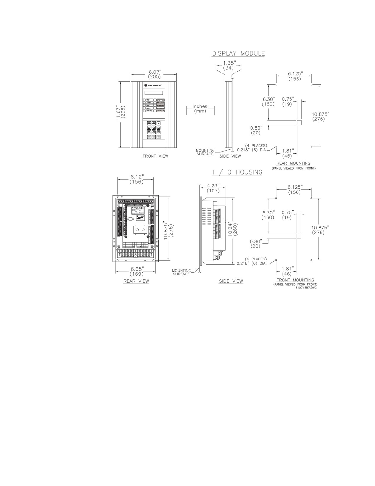
2: INSTALLATION MECHANICAL INSTALLATION .........................................................................................2-5
MECHANICAL INSTALLATION .............................................................................................. 2-5
TERMINAL IDENTIFICATION ...........................................................................................2-7
369 TERMINAL LIST ............................................................................................................ 2-7
TERMINAL LAYOUT .............................................................................................................. 2-9
ELECTRICAL INSTALLATION ...........................................................................................2-10
TYPICAL WIRING DIAGRAM ................................................................................................ 2-10
TYPICAL WIRING .................................................................................................................. 2-11
CONTROL POWER ................................................................................................................ 2-11
REMOTE DISPLAY ................................................................................................................. 2-11
OUTPUT RELAYS .................................................................................................................. 2-12
RS485 COMMUNICATIONS ............................................................................................... 2-12
3: USER INTERFACES FACEPLATE INTERFACE ...................................................................................................3-15
DISPLAY ................................................................................................................................ 3-15
LED INDICATORS ................................................................................................................. 3-15
RS232 PROGRAM PORT .................................................................................................... 3-16
KEYPAD ................................................................................................................................. 3-16
SETPOINT ENTRY .................................................................................................................. 3-17
ENERVISTA 369 SETUP INTERFACE .............................................................................3-18
HARDWARE AND SOFTWARE REQUIREMENTS ................................................................. 3-18
INSTALLING ENERVISTA 369 SETUP ............................................................................... 3-18
CONNECTING ENERVISTA 369 SETUP TO THE RELAY .............................................3-21
CONFIGURING SERIAL COMMUNICATIONS ....................................................................... 3-21
USING THE QUICK CONNECT FEATURE ............................................................................ 3-23
CONFIGURING ETHERNET COMMUNICATIONS ................................................................. 3-23
CONNECTING TO THE RELAY .............................................................................................. 3-25
4: KEYPAD SETPOINTS OVERVIEW ...........................................................................................................................4-27
KEYPAD SETPOINTS MAIN MENU ...................................................................................... 4-27
369 SETUP USING THE KEYPAD .....................................................................................4-31
KEYPAD SETPOINT ACCESS ................................................................................................ 4-31
S2 SYSTEM SETUP USING THE KEYPAD .......................................................................4-32
DESCRIPTION ........................................................................................................................ 4-32
EXAMPLE: CT/VT SETUP .................................................................................................... 4-32
S3 OVERLOAD PROTECTION ..........................................................................................4-34
DESCRIPTION ........................................................................................................................ 4-34
OVERLOAD CURVES ............................................................................................................ 4-35
OVERLOAD ALARM .............................................................................................................. 4-39
S4 CURRENT ELEMENTS ..................................................................................................4-40
DESCRIPTION ........................................................................................................................ 4-40

TOC–2 369 MOTOR MANAGEMENT RELAY – QUICKSTART GUIDE
TABLE OF CONTENTS
EXAMPLE: SHORT CIRCUIT .................................................................................................. 4-40
S8 POWER ELEMENTS ......................................................................................................4-42
DESCRIPTION ........................................................................................................................ 4-42
LEAD POWER FACTOR ........................................................................................................ 4-43
LAG POWER FACTOR .......................................................................................................... 4-43
POSITIVE REACTIVE POWER ............................................................................................... 4-44
NEGATIVE REACTIVE POWER ............................................................................................. 4-45
UNDERPOWER ...................................................................................................................... 4-46
REVERSE POWER ................................................................................................................. 4-47
S9 DIGITAL INPUTS ...........................................................................................................4-48
DIGITAL INPUT FUNCTIONS ................................................................................................ 4-48
SPARE SWITCH ..................................................................................................................... 4-50
EMERGENCY RESTART ......................................................................................................... 4-51
DIFFERENTIAL SWITCH ........................................................................................................ 4-51
SPEED SWITCH ..................................................................................................................... 4-51
REMOTE RESET ..................................................................................................................... 4-52
S10 ANALOG OUTPUTS ....................................................................................................4-53
ANALOG OUTPUTS .............................................................................................................. 4-53
S11 369 TESTING ...............................................................................................................4-55
TEST OUTPUT RELAYS ......................................................................................................... 4-55
TEST ANALOG OUTPUTS ..................................................................................................... 4-56
5: PRODUCT
DESCRIPTION
OVERVIEW ...........................................................................................................................5-57
METERED QUANTITIES ........................................................................................................ 5-57
PROTECTION FEATURES ...................................................................................................... 5-58
ADDITIONAL FEATURES ....................................................................................................... 5-59
SPECIFICATIONS ................................................................................................................5-60
INPUTS ................................................................................................................................... 5-60
OUTPUTS ...............................................................................................................................5-62
METERING ............................................................................................................................. 5-63
COMMUNICATIONS .............................................................................................................. 5-64
PROTECTION ELEMENTS ...................................................................................................... 5-65
MONITORING ELEMENTS .................................................................................................... 5-68
CONTROL ELEMENTS ........................................................................................................... 5-69
ENVIRONMENTAL SPECIFICATIONS .................................................................................... 5-69
LONG-TERM STORAGE ......................................................................................................... 5-70
APPROVALS/CERTIFICATION ............................................................................................... 5-70
TYPE TEST STANDARDS ....................................................................................................... 5-70
PRODUCTION TESTS ............................................................................................................ 5-71

369 MOTOR MANAGEMENT RELAY – QUICKSTART GUIDE 1–1
369 Motor Management Relay
Chapter 1: Introduction
GE Consumer & Industrial
Multilin
Introduction
1.1 Ordering
1.1.1 General Overview
The 369 Motor Management Relay is a digital relay that provides protection and
monitoring for three phase motors and their associated mechanical systems. A unique
feature of the 369 is its ability to ‘learn’ individual motor parameters and to adapt itself to
each application. Values such as motor inrush current, cooling rates and acceleration time
may be used to improve the 369’s protective capabilities.
The 369 offers optimum motor protection where other relays cannot, by using the
FlexCurve™ custom overload curve, or one of the fifteen standard curves.
The 369 has one RS232 front panel port and three RS485 rear ports. The Modbus RTU
protocol is standard to all ports. Setpoints can be entered via the front keypad or by using
the EnerVista 369 Setup software and a computer. Status, actual values and
troubleshooting information are also available via the front panel display or via
communications.
As an option, the 369 can individually monitor up to 12 RTDs. These can be from the stator,
bearings, ambient or driven equipment. The type of RTD used is software selectable.
Optionally available as an accessory is the remote RTD module which can be linked to the
369 via a fibre optic or RS485 connection.
The optional metering package provides VT inputs for voltage and power elements. It also
provides metering of V, kW, kvar, kVA, PF, Hz, and MWhrs. Three additional user
configurable analog outputs are included with this option along with one analog output
included as part of the base unit.
The Back-Spin Detection (B) option enables the 369 to detect the flow reversal of a pump
motor and enable timely and safe motor restarting. 369 options are available when
ordering the relay or as upgrades to the relay in the field. Field upgrades are via an option
enabling passcode available from GE Multilin, which is unique to each relay and option.

1–2 369 MOTOR MANAGEMENT RELAY – QUICKSTART GUIDE
ORDERING CHAPTER 1: INTRODUCTION
1.1.2 369 Functional Summary
The front view for all 369 Relay models is shown below, along with the rear view showing
the Profibus port, the Modbus/TCP port, and the DeviceNet port.
FIGURE 1–1: Front and Rear View
840702BM.CDR
FIBER OPTIC DATA LINK(F)
For harsh enviroments and or
hook up to RRTD
PROFIBUS-DP ( P )
PROFIBUS-DPV1 ( P1 )
BACKSPIN DETECTION(B)
20mV to 480V RMS
3 x RS485 Ports
3 Independent modbus
channels
1 ANALOG OUTPUT ( BASE UNIT )
3 ANALOG OUTPUTS (M,B)
VOLTAGE INPUTS(M)
0-240V wye or delta VT
connections.
GROUND CT INPUTS
5A, 1A and 50:0.25 taps
12 RTD INPUTS(R)
Field selectable type
CURRENT INPUTS
3 Phase CT inputs
5A, 1A, taps
CONTROL POWER
HI: 50-300 VDC/60-265 VAC
LO: 20-60 VDC / 20-48 VAC
4 OUTPUT RELAYS
Programmable alarm and trip
conditions activated by
programmable setpoints,
switch input, remote
communication control
Customer Accessible
Fuse
DIGITAL INPUTS
DISPLAY
40 Character alpha-numeric
LCD display for viewing
actual values, causes
of alarms and trips, and
programming setpoints
STATUS INDICATORS
LEDs indicate if motor is
stopped, starting, running,
overloaded or locked out
HELP KEY
Help key can be pressed at
any time to provide additional
information
KEYPAD
Used to select the display
of actual values, causes of
alarms, causes of trips, fault
diagnosis, and to program
setpoints
Rugged, corrosion and
flame retardent case.
STATUS INDICATORS
SERVICE LED
4 LEDs indicate when an
output is activated. When
an LED is lit, the cause of
the output relay operation
will be shown on the display.
indicates that a
self-diagnostic test failed, or
that the 369 is in Test Mode .
6
320

CHAPTER 1: INTRODUCTION ORDERING
369 MOTOR MANAGEMENT RELAY – QUICKSTART GUIDE 1–3
1.1.3 Relay Label Definition
1. The 369 order code at the time of leaving the factory.
2. The serial number of the 369.
3. The firmware installed at the factory. Note that this may no longer be the currently
installed firmware as it may have been upgraded in the field. The current firmware revi-
sion can be checked in the actual values section of the 369.
4. Specifications for the output relay contacts.
5. Certifications the 369 conforms with or has been approved to.
6. Factory installed options. These are based on the order code. Note that the 369 may
have had options upgraded in the field. The actual values section of the 369 can be
checked to verify this.
7. Control power ratings for the 369 as ordered. Based on the HI/LO rating from the order
code.
8. Pollution degree.
9. Overvoltage category.
10. IP code.
11. Modification number for any factory-ordered mods.
12. Insulative voltage rating.
CE
g
INPUT POWER:
MODEL: 369-HI-R-B-F-P-0
MAXIMUM CONTACT RATING
250 VAC 8A RESISTIVE
1/4 HP 125 VAC 1/2 HP 250 VAC
SERIAL No: M53C07000001
FIRMWARE: 53CMC320.000
POLLUTION DEGREE: 2 IP CODE: 50X
50-300 VDC
60-265 VAC
485mA MAX.
50/60Hz or DC MOD:
12 RTDs:
BACKSPIN
FIBER OPTIC PORT
PROFIBUS
OPTIONS
INSULATIVE VOLTAGE: 2
NONE
OVERVOLTAGE CATAGORY: II
1
7
2
8
3
9
4
10 11
56
12
840350AA.CDR
UL

1–4 369 MOTOR MANAGEMENT RELAY – QUICKSTART GUIDE
ORDERING CHAPTER 1: INTRODUCTION

369 MOTOR MANAGEMENT RELAY – QUICKSTART GUIDE 2–5
369 Motor Management Relay
Chapter 2: Installation
GE Consumer & Industrial
Multilin
Instal lation
2.1 Mechanical Installation
2.1.1 Mechanical Installation
The 369 is contained in a compact plastic housing with the keypad, display,
communication port, and indicators/targets on the front panel. The unit should be
positioned so the display and keypad are accessible. To mount the relay, make cutout and
drill mounting holes as shown below. Mounting hardware (bolts and washers) is provided
with the relay. Although the relay is internally shielded to minimize noise pickup and
interference, it should be mounted away from high current conductors or sources of
strong magnetic fields.
FIGURE 2–1: Physical Dimensions

2–6 369 MOTOR MANAGEMENT RELAY – QUICKSTART GUIDE
MECHANICAL INSTALLATION CHAPTER 2: INSTALLATION
FIGURE 2–2: Split Mounting Dimensions

CHAPTER 2: INSTALLATION TERMINAL IDENTIFICATION
369 MOTOR MANAGEMENT RELAY – QUICKSTART GUIDE 2–7
2.2 Terminal Identification
2.2.1 369 Terminal List
TERMINAL WIRING CONNECTION
1RTD1+
2RTD1–
3 RTD1 COMPENSATION
4RTD1SHIELD
5RTD2+
6RTD2–
7 RTD2 COMPENSATION
8RTD2SHIELD
9RTD3+
10 RTD3 –
11 RTD3 COMPENSATION
12 RTD3 SHIELD
13 RTD4 +
14 RTD4 –
15 RTD4 COMPENSATION
16 RTD4 SHIELD
17 RTD5 +
18 RTD5 –
19 RTD5 COMPENSATION
20 RTD5 SHIELD
21 RTD6 +
22 RTD6 –
23 RTD6 COMPENSATION
24 RTD6 SHIELD
25 RTD7 +
26 RTD7 –
27 RTD7 COMPENSATION
28 RTD7 SHIELD
29 RTD8 +
30 RTD8 –
31 RTD8 COMPENSATION
32 RTD8 SHIELD
33 RTD9 +
34 RTD9 –
35 RTD9 COMPENSATION
36 RTD9 SHIELD
37 RTD10 +
38 RTD10 –
39 RTD10 COMPENSATION
40 RTD10 SHIELD
41 RTD11 +
42 RTD11 –
43 RTD11 COMPENSATION

2–8 369 MOTOR MANAGEMENT RELAY – QUICKSTART GUIDE
TERMINAL IDENTIFICATION CHAPTER 2: INSTALLATION
44 RTD11 SHIELD
45 RTD12 +
46 RTD12 –
47 RTD12 COMPENSATION
48 RTD12 SHIELD
51 SPARE SW
52 SPARE SW COMMON
53 DIFFERENTIAL INPUT SW
54 DIFFERENTIAL INPUT SW COMMON
55 SPEED SW
56 SPEED SW COMMON
57 ACCESS SW
58 ACCESS SW COMMON
59 EMERGENCY RESTART SW
60 EMERGENCY RESTART SW COMMON
61 EXTERNAL RESET SW
62 EXTERNAL RESET SW COMMON
71 COMM1 RS485 +
72 COMM1 RS485 –
73 COMM1 SHIELD
74 COMM2 RS485 +
75 COMM2 RS485 –
76 COMM2 SHIELD
77 COMM3 RS485 +
78 COMM3 RS485 –
79 COMM3 SHIELD
80 ANALOG OUT 1
81 ANALOG OUT 2
82 ANALOG OUT 3
83 ANALOG OUT 4
84 ANALOG COM
85 ANALOG SHIELD
90 BACKSPIN VOLTAGE
91 BACKSPIN NEUTRAL
92 PHASE A CURRENT 5A
93 PHASE A CURRENT 1A
94 PHASE A COMMON
95 PHASE B CURRENT 5A
96 PHASE B CURRENT 1A
97 PHASE B COMMON
98 PHASE C CURRENT 5A
99 PHASE C CURRENT 1A
100 PHASE C COMMON
101 NEUT/GND CURRENT 50:0.025A
102 NEUT/GND CURRENT 1A
103 NEUT/GND CURRENT 5A
104 NEUT/GND COMMON
105 PHASE A VOLTAGE
106 PHASE A NEUTRAL
TERMINAL WIRING CONNECTION

CHAPTER 2: INSTALLATION TERMINAL IDENTIFICATION
369 MOTOR MANAGEMENT RELAY – QUICKSTART GUIDE 2–9
2.2.2 Terminal Layout
FIGURE 2–3: TERMINAL LAYOUT
107 PHASE B VOLTAGE
108 PHASE B NEUTRAL
109 PHASE C VOLTAGE
110 PHASE C NEUTRAL
111 TRIP NC
112 TRIP COMMON
113 TRIP NO
114 ALARM NC
115 ALARM COMMON
116 ALARM NO
117 AUX1 NC
118 AUX1 COMMON
119 AUX1 NO
120 AUX2 NC
121 AUX2 COMMON
122 AUX2 NO
123 POWER FILTER GROUND
124 POWER LINE
125 POWER NEUTRAL
126 POWER SAFETY
TERMINAL WIRING CONNECTION

2–10 369 MOTOR MANAGEMENT RELAY – QUICKSTART GUIDE
ELECTRICAL INSTALLATION CHAPTER 2: INSTALLATION
2.3 Electrical Installation
2.3.1 Typical Wiring Diagram
FIGURE 2–4: Typical Wiring

CHAPTER 2: INSTALLATION ELECTRICAL INSTALLATION
369 MOTOR MANAGEMENT RELAY – QUICKSTART GUIDE 2–11
2.3.2 Typical Wiring
The 369 can be connected to cover a broad range of applications and wiring will vary
depending upon the user’s protection scheme. This section will cover most of the typical
369 interconnections.
In this section, the terminals have been logically grouped together for explanatory
purposes. A typical wiring diagram for the 369 is shown above in FIGURE 2–4: Typical
Wiring on page 2–10 and the terminal arrangement has been detailed in FIGURE 2–3:
TERMINAL LAYOUT on page 2–9. For further information on applications not covered here,
refer to the 369 Instruction Manual, or contact the factory for further information.
Hazard may result if the product is not used for intended purposes. This equipment can
only be serviced by trained personnel.
2.3.3 Control Power
VERIFY THAT THE CONTROL POWER SUPPLIED TO THE RELAY IS WITHIN THE RANGE
COVERED BY THE ORDERED 369 RELAY’S CONTROL POWER.
The 369 has a built-in switchmode supply. It can operate with either AC or DC voltage
applied to it.
Extensive filtering and transient protection has been incorporated into the 369 to ensure
reliable operation in harsh industrial environments. Transient energy is removed from the
relay and conducted to ground via the ground terminal. This terminal must be connected
to the cubicle ground bus using a 10 AWG wire or a ground braid. Do not daisy-chain
grounds with other relays or devices. Each should have its own connection to the ground
bus.
The internal supply is protected via a 3.15 A slo-blo fuse that is accessible for replacement.
If it must be replaced ensure that it is replaced with a fuse of equal size (see FUSE on page
5–60).
2.3.4 Remote Display
The 369 display can be separated and mounted remotely up to 15 feet away from the
main relay. No separate source of control power is required for the display module. A 15
feet standard shielded network cable is used to make the connection between the display
module and the main relay. A recommended and tested cable is available from GE Multilin.
The cable should be wired as far away as possible from high current or voltage carrying
cables or other sources of electrical noise.
Table 2–1: 369 POWER SUPPLY RANGES
369 POWER SUPPLY AC RANGE DC RANGE
HI 60 to 265 V 50 to 300 V
LO 20 to 48 V 20 to 60 V

2–12 369 MOTOR MANAGEMENT RELAY – QUICKSTART GUIDE
ELECTRICAL INSTALLATION CHAPTER 2: INSTALLATION
In addition the display module must be grounded if mounted remotely. A ground screw is
provided on the back of the display module to facilitate this. A 12 AWG wire is
recommended and should be connected to the same ground bus as the main relay unit.
The 369 relay will still function and protect the motor without the display connected.
2.3.5 Output Relays
The 369 provides four (4) form C output relays. They are labeled Trip, Aux 1, Aux 2, and
Alarm. Each relay has normally open (NO) and normally closed (NC) contacts and can
switch up to 8 A at either 250 V AC or 30 V DC with a resistive load. The NO or NC state is
determined by the ‘no power’ state of the relay outputs.
All four output relays may be programmed for fail-safe or non-fail-safe operation. When in
fail-safe mode, output relay activation or a loss of control power will cause the contacts to
go to their power down state.
Example:
•Afail-safe NO contact closes when the 369 is powered up (if no prior unreset trip
conditions) and will open when activated (tripped) or when the 369 loses control
power.
•Anon-fail-safe NO contact remains open when the 369 is powered up (unless a prior
unreset trip condition) and will close only when activated (tripped). If control power is
lost while the output relay is activated (NO contacts closed) the NO contacts will open.
Thus, in order to cause a trip on loss of control power to the 369, the Trip relay should be
programmed as fail-safe. See the figure below for typical wiring of contactors and
breakers for fail-safe and non-fail-safe operation. Output relays remain latched after
activation if the fault condition persists or the protection element has been programmed
as latched. This means that once this relay has been activated it remains in the active state
until the 369 is manually reset.
The Trip relay cannot be reset if a timed lockout is in effect. Lockout time will be adhered to
regardless of whether control power is present or not. The relay contacts may be reset if
motor conditions allow, by pressing the RESET key, using the REMOTE RESET switch or via
communications. The Emergency Restart feature overrides all features to reset the 369.
The rear of the 369 relay shows output relay contacts in their power down state.
Note In locations where system voltage disturbances cause voltage levels to dip below the
control power range listed in specifications, any relay contact programmed as fail-safe
may change state. Therefore, in any application where the ‘process’ is more critical
than the motor, it is recommended that the trip relay contacts be programmed as non-
fail-safe. If, however, the motor is more critical than the ‘process’ then program the trip
contacts as fail-safe.
2.3.6 RS485 Communications
Three independent two-wire RS485 ports are provided. If option (F), the fiber optic port, is
installed and used, the COMM 3 RS485 port may not be used. The RS485 ports are isolated
as a group.

CHAPTER 2: INSTALLATION ELECTRICAL INSTALLATION
369 MOTOR MANAGEMENT RELAY – QUICKSTART GUIDE 2–13
Up to 32 369s (or other devices) can be daisy-chained together on a single serial
communication channel without exceeding the driver capability. For larger systems,
additional serial channels must be added. Commercially available repeaters may also be
used to increase the number of relays on a single channel to a maximum of 254. Note that
there may only be one master device per serial communication link.
Connections should be made using shielded twisted pair cables (typically 24 AWG).
Suitable cables should have a characteristic impedance of 120 ohms (e.g. Belden #9841)
and total wire length should not exceed 4000 ft. Commercially available repeaters can be
used to extend transmission distances.
Voltage differences between remote ends of the communication link are not uncommon.
For this reason, surge protection devices are internally installed across all RS485 terminals.
Internally, an isolated power supply with an optocoupled data interface is used to prevent
noise coupling. The source computer/PLC/SCADA system should have similar transient
protection devices installed, either internally or externally, to ensure maximum reliability.
To ensure that all devices in a daisy-chain are at the same potential, it is imperative
that the common terminals of each RS485 port are tied together and grounded in one
location only, at the master. Failure to do so may result in intermittent or failed
communications.
Correct polarity is also essential. 369 relays must be wired with all ‘+’ terminals connected
together, and all ‘–’ terminals connected together. Each relay must be daisy-chained to the
next one. Avoid star or stub connected configurations. The last device at each end of the
daisy-chain should be terminated with a 120 ohm ¼ watt resistor in series with a 1 nF
capacitor across the ‘+’ and ‘–’ terminals. Observing these guidelines will result in a reliable
communication system that is immune to system transients.
FIGURE 2–5: RS485 Wiring

2–14 369 MOTOR MANAGEMENT RELAY – QUICKSTART GUIDE
ELECTRICAL INSTALLATION CHAPTER 2: INSTALLATION

369 MOTOR MANAGEMENT RELAY – QUICKSTART GUIDE 3–15
369 Motor Management Relay
Chapter 3: User Interfaces
GE Consumer & Industrial
Multilin
User Interfaces
3.1 Faceplate Interface
3.1.1 Display
All messages are displayed on a 40-character LCD display to make them visible under poor
lighting conditions and from various viewing angles. Messages are displayed in plain
English and do not require the aid of an instruction manual for deciphering. While the
keypad and display are not actively being used, the display will default to user defined
status messages. Any trip, alarm, or start inhibit will automatically override the default
messages and appear on the display.
3.1.2 LED Indicators
There are ten LED indicators, as follows:
•TRIP: Trip relay has operated (energized)
•ALARM: Alarm relay has operated (energized)
•AUX 1: Auxiliary relay has operated (energized)
•AUX 2: Auxiliary relay has operated (energized)
•SERVICE: Relay in need of technical service.
•STOPPED: Motor is in the Stopped condition
•STARTING: Motor is in the Starting condition
•RUNNING: Motor is in the Running condition
•OVERLOAD: Motor is in the Overload condition
•LOCKOUT: Motor is in the Lockout condition

3–16 369 MOTOR MANAGEMENT RELAY – QUICKSTART GUIDE
FACEPLATE INTERFACE CHAPTER 3: USER INTERFACES
FIGURE 3–1: LED Indicators - Enhanced Faceplate
FIGURE 3–2: LED Indicators - Basic Faceplate
3.1.3 RS232 Program Port
This port is intended for connection to a portable PC. Setpoint files may be created at any
location and downloaded through this port using the EnerVista 369 Setup software. Local
interrogation of Setpoints and Actual Values is also possible. New firmware may be
downloaded to the 369 flash memory through this port. Upgrading of the relay firmware
does not require a hardware EPROM change.
3.1.4 Keypad
The 369 messages are organized into pages under the main headings, Setpoints and
Actual Values. The [SETPOINTS] key is used to navigate through the page headers of the
programmable parameters. The [ACTUAL VALUES] key is used to navigate through the
page headers of the measured parameters.
Each page is broken down further into logical subgroups of messages. The [PAGE] up and
down keys may be used to navigate through the subgroups.
• [SETPOINTS]: This key may be used to navigate through the page headers of the
programmable parameters. Alternately, one can press this key followed by using
the Page Up / Page Down keys.
• [ACTUAL VALUES]: This key is used to navigate through the page headers of the
measured parameters. Alternately, one can scroll through the pages by pressing
the Actual Values key followed by using the Page Up / Page Down keys.
Other manuals for 369
1
Table of contents
Other GE Relay manuals