GEK-1
00636
NOTE:
The
pickup
level
of
the
IT
unit
could
be
different
from
the
pickup
level
of
the
BFT
unit.
If
the
IT
unit
is
not
supervised
by
a
timer,
its
pickup
level
will
be
equivalent
to
the
following
equation:
At
60
I-Iz
IT
pickup
=
.535
x
BFT
Pickup
At
50
Hz
iT
pickup
=
.453
x
BFT
Pickup
The
seal-in
contact provided
by
the
IT
function
is
for
those
who
wish
to
use
such
a
feature.
The
seal-in circuit
has
a
slight
time
delay
to
provide
additional
security
against
seal-in
operations
resulting
from
such
causes
as
surges
or
transients. The
purpose
of
the
seal-in
circuit
is
to
ride
over
contact
bounce
in
the
initiating
contacts
(if
such
bounce
exists)
and
to
maintain
the
DC input
of
the
SBC
in
the event
of
a
zero-voltage
fault
that
results
in
resetting
of
the
initiating
protective
relays
before
the
breaker-failure
timer
can
produce
an
output.
The
seal-in
circuit should
be
used
with
caution,
since
it
can
reduce
the security
of
the scheme
during testing
if
the
level
detector
is
set
to
pick up
below
load
current.
Note that
most
static
line-relaying systems
include
a
seal-in
function
SO
that
the
BFI
contacts
remain
closed
until
the
fault
is
cleared.
For the
SBC223A,B,
or
C,
to
implement
the
Seal-In
feature
with
the
IT
contact
at
Stud
II,
the
JI
connector, located
in
the
upper-left-hand
corner
of
the
backplane
(see
Figure
16),
must
have
a
jumper
connecting terminals
I
and
2.
This
will
no
longer
leave the
IT
contact
isolated.
To
implement
the Seal-In
function
with
Stud
9,
the
JI
connector
must have
a
jumper
connecting
terminals
2
and
3.
This
will
flO
longer
leave
Stud
9
and
the
IT
contact
isolated. Both methods
of
Seal-In
can
be
seen
in
the
External Connection
and
Logic
Diagrams
for
each
relay.
To
eliminate
all
Seal-In function, place
the
jumper
on
JI
connected
to
only
one
terminal
(Do
Not
short
together
any
two
terminals).
This
is
the
configuration
with
which
the
original
SBC23
was
shipped.
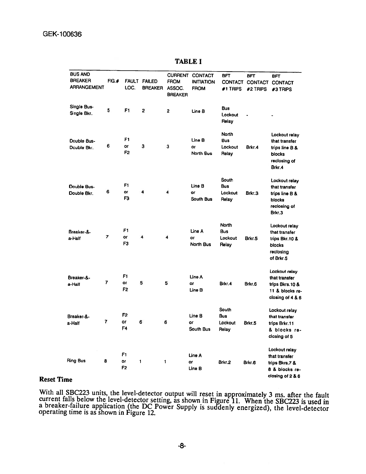
The routing
of
the
contact-initiation
inputs
and
the
BFT
outputs
depend
upon
the
bus and
breaker
arrangement.
The static
breaker-failure
relaying
schemes
described
in
this
book
are
intended
for
application
on
a
per-breaker
basis.
That
is,
there
is
one
breaker-failure
relay
associated
with
each
breaker
in
a
bus array.
On
this
basis
the
current
inputs
to
a
breaker-failure
relay
must
come
from
CT’s
that
measure
the
current
in
the
associated
breaker.
The
trip
outputs
must be
routed
to
initiate
the
tripping (or
transferred
tripping)
of
all
backup
breakers
necessary
to
clear the
fault.
The
listing
in
Table
I
covers
the
bus
arrangements that
are
in
common
use
today.
They are
the
single-bus-single-breaker, double-bus-double-breaker,
breaker-and-a-half,
and ring-bus
arrangements,
and
they
are
shown
in
Figures
6, 7,
8
and
9
respectively.
Each
listing
in
Table
I
indicates
the
assumed
fault
location,
the
breaker
which
is
assumed
to
have
failed,
the
contact
initiation
that
activates
the
relay,
and
which
breakers
or
lockout
relays
should
be
tripped
by
the
BFT
contacts.
For
example,
in
a
single-bus-single-breaker
arrangement
(Figure
6),
if
breaker
#2
is
to
he
protected,
the
level
detector
(LD)
receives
the
currents
associated
with
breaker
#2.
The
contact
initiation
is
from
the
protective
relays
of
line
B.
If
breaker
#2
fails
for
a
fault at
Fl, the
breaker-failure
relay
operates
and the BFT
contact
#1
trips
the
bus
lockout
relay.
For
another
example,
consider
the
ring
bus
arrangement
that
is
shown
in
Figure
9.
If
breaker
1
is
to
he
protected,
the
level
detector
receives
the
currents
associated
with
breaker
1.
The
contact
initiation
is
from the
protective
relays
of
line
A
for
a
fault
at
Fl
or
the
protective
relays
of
line
B
for
a
fault
at
F2.
Assuming
breaker
I
fails
for
a
fault
at
Fl,
the
relay
operates
and
the
BFT
contacts
trip
the
following:
BFT
#1
trips
breaker
2
and
BFT
#2
trips
breaker
6;
BFT
#3
trips
the
lockout
relay
that
transfer
trips
breakers
7
and
8
and
blocks
reclosing
of
2
and
6.
-7-