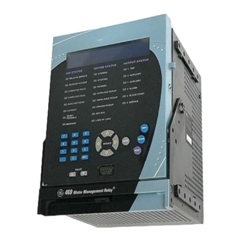
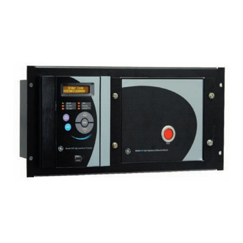
GE Multilin 745 User manual

745
Transformer Management Relay
INSTRUCTION MANUAL
Firmware Revision: 4.00
Manual P/N: 1601-0161-A1
Manual Order Code: GEK-106635
Copyright © 2004 GE Multilin
GE Multilin
215 Anderson Avenue, Markham, Ontario
Canada L6E 1B3
Tel: (905) 294-6222 Fax: (905) 201-2098
Internet: http://www.GEindustrial.com/multilin
Titl
e
P
age
g
GE Industrial Systems
814768AH.CDR
IN SERVICE
LOCAL
SETPOINT GROUP 2
LOAD-LIMIT
REDUCED
TRIP
SELF-TEST
ERROR
SETPOINT GROUP 3
TRANSFORMER
DE-ENERGIZED
ALARM
PICKUP
TEST MODE
TRANSFORMER
OVERLOAD
SETPOINT GROUP 1 PHASE A
PHASE B
PHASE C
GROUNDMESSAGE
PROGRAM PORT SETPOINT 789
456
12 3
.0HELP
MESSAGE
VAL UE
ACTUAL
ESCAPE
ENTER
RESET
NEXT
DIFFERENTIAL
BLOCKED
745 STATUS SYSTEM STATUS CONDITIONS
SETPOINT GROUP 4
ISO9001:2000
G
E
M
U
L
T
I
L
I
N
R
E
G
I
S
T
E
R
E
D
GE Multilin's Quality
Management System is
registered to ISO9001:2000
QMI # 005094
UL # A3775


745
Transformer Management Relay
http://www.GEindustrial.com/multilin iii
GE Multilin
Table of Contents
GETTING STARTED Important Procedures
Cautions and Warnings...................................................................................................................... 1-1
Inspection Checklist ............................................................................................................................ 1-1
Manual Organization .......................................................................................................................... 1-2
Using the Relay
Menu Navigation ................................................................................................................................ 1-2
Panel Keying Example........................................................................................................................ 1-4
Changing Setpoints
Introduction ......................................................................................................................................... 1-5
Using the HELP Key............................................................................................................................ 1-5
Numerical Setpoints ........................................................................................................................... 1-5
Enumeration Setpoints....................................................................................................................... 1-5
Text Setpoints ..................................................................................................................................... 1-6
Security
Installation ........................................................................................................................................... 1-7
Changing the Passcode ...................................................................................................................... 1-7
Disabling and Enabling Passcode Security ...................................................................................... 1-8
OVERVIEW Introduction
Description .......................................................................................................................................... 2-1
Protection Features............................................................................................................................. 2-2
Order Codes ........................................................................................................................................ 2-3
Specifications
Applicability......................................................................................................................................... 2-4
Inputs ................................................................................................................................................... 2-4
Protection Elements............................................................................................................................ 2-5
Outputs ................................................................................................................................................ 2-6
Miscellaneous ..................................................................................................................................... 2-7
INSTALLATION Drawout Case
Case Description ................................................................................................................................. 3-1
Panel Cutout ........................................................................................................................................ 3-1
Case Mounting .................................................................................................................................... 3-2
Unit Withdrawal and Insertion........................................................................................................... 3-3
Typical Wiring
Description .......................................................................................................................................... 3-5

Table of Contents745
Generator Management Relay
http://www.GEindustrial.com/multilin
iv GE Multilin
Rear Terminal Layout..........................................................................................................................3-5
Wiring Diagrams..................................................................................................................................3-7
Phase Sequence and Transformer Polarity.......................................................................................3-9
AC Current Transformer Inputs..........................................................................................................3-9
AC Voltage Input................................................................................................................................3-10
Logic Inputs........................................................................................................................................3-10
Control Power ....................................................................................................................................3-11
Analog Input.......................................................................................................................................3-11
Tap Position Input..............................................................................................................................3-11
RTD Driver/Sensor.............................................................................................................................3-11
Output Relays ....................................................................................................................................3-12
Solid State Trip Output .....................................................................................................................3-12
Analog Outputs..................................................................................................................................3-12
RS485 / RS422 Communications......................................................................................................3-13
RS232 Front Panel Program Port .....................................................................................................3-14
IRIG-B..................................................................................................................................................3-15
Dielectric Strength.............................................................................................................................3-15
INTERFACES Hardware Interface
Front Panel ...........................................................................................................................................4-1
Display..................................................................................................................................................4-2
LEDs......................................................................................................................................................4-2
LED Indicators......................................................................................................................................4-2
Program Port........................................................................................................................................4-3
Keypad..................................................................................................................................................4-3
Setpoint Entry ......................................................................................................................................4-5
Diagnostic Messages ..........................................................................................................................4-6
Flash Messages ...................................................................................................................................4-6
enerVista Software Interface
Overview ..............................................................................................................................................4-7
Hardware..............................................................................................................................................4-7
Installing the enerVista 745 Setup Software .....................................................................................4-8
Connecting enerVista 745 Setup to the Relay
Configuring Serial Communications................................................................................................4-11
Using the Quick Connect Feature.....................................................................................................4-12
Configuring Ethernet Communications ...........................................................................................4-13
Connecting to the Relay....................................................................................................................4-14
Working with Setpoints and Setpoint Files
Engaging a Device.............................................................................................................................4-15
Entering Setpoints .............................................................................................................................4-15
File Support........................................................................................................................................4-16
Using Setpoints Files.........................................................................................................................4-16
Upgrading Relay Firmware
Description .........................................................................................................................................4-21
Saving Setpoints To A File ...............................................................................................................4-21
Loading New Firmware.....................................................................................................................4-21
Advanced enerVista 745 Setup Features
Triggered Events ...............................................................................................................................4-23
Waveform Capture (Trace Memory)................................................................................................4-23
Trending (Data Logger).....................................................................................................................4-25
Event Recorder ..................................................................................................................................4-27
Modbus User Map.............................................................................................................................4-28
Viewing Actual Values ......................................................................................................................4-29
Using enerVista Viewpoint with the 745
Plug and Play Example .....................................................................................................................4-31
SETPOINTS Overview
Setpoint Message Map .......................................................................................................................5-1

Table of Contents 745
Generator Management Relay
http://www.GEindustrial.com/multilin v
GE Multilin
Setpoint Entry ..................................................................................................................................... 5-4
Setpoint Write Access ........................................................................................................................ 5-4
Auto-Configuration
Introduction ......................................................................................................................................... 5-5
Dynamic CT Ratio Mismatch Correction........................................................................................... 5-5
Phase Shifts on Three-Phase Transformers ..................................................................................... 5-7
Phase Angle Correction...................................................................................................................... 5-9
Zero-Sequence Component Removal ............................................................................................. 5-10
Transformer Types ........................................................................................................................... 5-11
Phase Shifts....................................................................................................................................... 5-23
S1 745 Setup
Passcode............................................................................................................................................ 5-24
Preferences........................................................................................................................................ 5-24
Communications............................................................................................................................... 5-25
Resetting............................................................................................................................................ 5-27
Clock................................................................................................................................................... 5-27
Default Messages.............................................................................................................................. 5-27
Scratchpad......................................................................................................................................... 5-28
Installation ......................................................................................................................................... 5-29
Upgrade Options............................................................................................................................... 5-29
S2 System Setup
Description ........................................................................................................................................ 5-30
Transformer....................................................................................................................................... 5-30
Windings 1 to 3 ................................................................................................................................. 5-32
Onload Tap Changer......................................................................................................................... 5-33
Harmonics ......................................................................................................................................... 5-33
FlexCurves™ ..................................................................................................................................... 5-34
Voltage Input ..................................................................................................................................... 5-34
Ambient Temperature ...................................................................................................................... 5-35
Analog Input...................................................................................................................................... 5-36
Demand Metering ............................................................................................................................. 5-36
Analog Outputs 1 to 7....................................................................................................................... 5-37
S3 Logic Inputs
Description ........................................................................................................................................ 5-38
Logic Inputs 1 to 16........................................................................................................................... 5-38
Virtual Inputs 1 to 16......................................................................................................................... 5-39
S4 Elements
Introduction to Elements .................................................................................................................. 5-39
Setpoint Group.................................................................................................................................. 5-41
Differential Element .......................................................................................................................... 5-41
Instantaneous Differential ................................................................................................................ 5-48
Phase Overcurrent ............................................................................................................................ 5-49
Neutral Overcurrent.......................................................................................................................... 5-56
Ground Overcurrent ......................................................................................................................... 5-59
Restricted Ground............................................................................................................................. 5-61
Negative Sequence Overcurrent ..................................................................................................... 5-64
Frequency .......................................................................................................................................... 5-66
Overexcitation ................................................................................................................................... 5-71
Harmonics ......................................................................................................................................... 5-75
Insulation Aging ................................................................................................................................ 5-78
Analog Input Level............................................................................................................................ 5-82
Current Demand................................................................................................................................ 5-83
Transformer Overload ...................................................................................................................... 5-84
Tap Changer Failure ......................................................................................................................... 5-85
S5 Outputs
Description ........................................................................................................................................ 5-86
Introduction to FlexLogic™.............................................................................................................. 5-86
FlexLogic™ Rules.............................................................................................................................. 5-87
Output Relays.................................................................................................................................... 5-88
Trace Memory................................................................................................................................... 5-90
Virtual Outputs .................................................................................................................................. 5-91
Timers ................................................................................................................................................ 5-91

Table of Contents745
Generator Management Relay
http://www.GEindustrial.com/multilin
vi GE Multilin
S6 Testing
Description .........................................................................................................................................5-91
Output Relays ....................................................................................................................................5-92
Analog Outputs..................................................................................................................................5-92
Simulation..........................................................................................................................................5-93
Factory Service ..................................................................................................................................5-97
ACTUAL VALUES Overview
Message Map.......................................................................................................................................6-1
Description ...........................................................................................................................................6-3
A1 Status
Date and Time......................................................................................................................................6-3
Logic Inputs..........................................................................................................................................6-3
Virtual Inputs........................................................................................................................................6-3
Output Relays ......................................................................................................................................6-4
Virtual Outputs.....................................................................................................................................6-4
Self-Test Errors ....................................................................................................................................6-4
A2 Metering
Current..................................................................................................................................................6-5
Harmonic Content................................................................................................................................6-8
Frequency...........................................................................................................................................6-10
Tap Changer.......................................................................................................................................6-10
Voltage ...............................................................................................................................................6-10
Demand ..............................................................................................................................................6-10
Ambient Temperature.......................................................................................................................6-11
Loss of Life .........................................................................................................................................6-12
Analog Input.......................................................................................................................................6-12
Power..................................................................................................................................................6-12
Energy ................................................................................................................................................6-12
A3 Event Recorder
Event Data Clear ................................................................................................................................6-13
Event Records ....................................................................................................................................6-14
A4 Product Information
Technical Support .............................................................................................................................6-16
Revision Codes ..................................................................................................................................6-17
Calibration..........................................................................................................................................6-17
Target and Flash Messages
Target Messages ...............................................................................................................................6-17
Self-Test Errors ..................................................................................................................................6-19
Flash Messages .................................................................................................................................6-21
COMMISSIONING General
Introduction..........................................................................................................................................7-1
Testing Philosophy..............................................................................................................................7-1
Safety Precautions...............................................................................................................................7-2
Conventions .........................................................................................................................................7-2
Test Equipment....................................................................................................................................7-2
Preliminary Work
Description ...........................................................................................................................................7-4
Dielectric Strength Testing .................................................................................................................7-4
Logic Inputs and Output Relays
Logic Inputs..........................................................................................................................................7-5
Output Relays ......................................................................................................................................7-6
Metering
Description ...........................................................................................................................................7-6
Current Inputs ......................................................................................................................................7-6

Table of Contents 745
Generator Management Relay
http://www.GEindustrial.com/multilin vii
GE Multilin
Voltage Input ....................................................................................................................................... 7-7
Transformer Type Selection .............................................................................................................. 7-8
Ambient Temperature Input .............................................................................................................. 7-9
Analog Outputs ................................................................................................................................. 7-11
Tap Position....................................................................................................................................... 7-11
Protection Schemes
Precautions........................................................................................................................................ 7-11
Harmonic Restrained Percent Differential....................................................................................... 7-11
Instantaneous Differential Protection.............................................................................................. 7-17
Phase Time Overcurrent................................................................................................................... 7-18
Phase Instantaneous Overcurrent 1 ................................................................................................ 7-20
Phase Instantaneous Overcurrent 2 ................................................................................................ 7-20
Neutral Time Overcurrent ................................................................................................................ 7-21
Neutral Instantaneous Overcurrent 1.............................................................................................. 7-22
Neutral Instantaneous Overcurrent 2.............................................................................................. 7-23
Ground Time Overcurrent................................................................................................................ 7-23
Ground Instantaneous Overcurrent 1.............................................................................................. 7-25
Ground Instantaneous Overcurrent 2.............................................................................................. 7-26
Restricted Ground Fault Polarity Test ............................................................................................. 7-26
Restricted Ground Fault Element Test ............................................................................................ 7-27
Negative Sequence Time Overcurrent............................................................................................ 7-28
Negative Sequence Instantaneous Overcurrent............................................................................. 7-30
Frequency .......................................................................................................................................... 7-31
Overexcitation ................................................................................................................................... 7-36
Insulation Aging ................................................................................................................................ 7-37
Tap Monitor Failure .......................................................................................................................... 7-38
Auxiliary Protection and Monitoring Functions
THD Level Scheme............................................................................................................................ 7-38
Harmonic Derating Function ............................................................................................................ 7-39
Transformer Overload ...................................................................................................................... 7-40
Placing the Relay Into Service
Precautions........................................................................................................................................ 7-40
Procedure .......................................................................................................................................... 7-40
APPENDIX Change Notes
Revision History .................................................................................................................................. 8-1
Changes to the 745 Manual ............................................................................................................... 8-1
EU Declaration of Conformity
GE Multilin Warranty
Warranty Statement ........................................................................................................................... 8-3
INDEX

Table of Contents745
Generator Management Relay
http://www.GEindustrial.com/multilin
viii GE Multilin

Getting Started
Important Procedures 745
Transformer Management Relay
http://www.GEindustrial.com/multilin 1–1
GE Multilin
1 Getting Started
Important Procedures
Cautions and Warnings Please read this chapter to guide you through the initial setup of your new relay.
Before attempting to install or use the relay, it is
imperative that all WARNINGS and CAUTIONS in this
manual are reviewed to help prevent personal injury,
equipment damage, and/or downtime.
Inspection Checklist • Open the relay packaging and inspect the unit for physical damage.
• View the rear nameplate and verify that the correct model has been ordered.
• Ensure that the following items are included:
– Instruction Manual
– GE enerVista CD (includes software and relay documentation)
– mounting screws
– registration card (attached as the last page of the manual)
• Fill out the registration form and mail it back to GE Multilin (include the serial
number located on the rear nameplate).
• For product information, instruction manual updates, and the latest software
updates, please visit the GE Multilin website at http://www.GEindustrial.com/
multilin.
If there is any noticeable physical damage, or any of the contents listed are
missing, please contact GE Multilin immediately.
GE Multilin contact information and call center for product support:
GE Multilin
215 Anderson Avenue
Markham, Ontario
Canada L6E 1B3
Telephone: (905) 294-6222, toll-free 1-800-547-8629 (North America only)
Fax: (905) 201-2098
E-mail: [email protected]
Home Page: http://www.GEindustrial.com/multilin
CAUTIONWARNING
NOTE

Using the Relay745
Transformer Management Relay
Getting Started
http://www.GEindustrial.com/multilin
1–2 GE Multilin
Manual Organization Reading a lengthy instruction manual on a new product is not a task most people
enjoy. To speed things up, this introductory chapter provides guidelines for basic
relay usability. Important wiring considerations and precautions discussed in
Electrical Installation on page 3–6 should be observed for reliable operation.
Detailed information regarding accuracy, output relay contact ratings, and so forth
are detailed in Specifications on page 2–5. The remainder of this manual should be
read and kept for reference to ensure maximum benefit from the 745 Transformer
Management Relay. For further information, please consult your local sales
representative or the factory. Comments about new features or modifications for
your specific requirements are welcome and encouraged.
Setpoints and actual values are indicated as follows in the manual:
A2 METERING !" LOSS OF LIFE !HOTTEST-SPOT WINDING TEMPERATURE
This ‘path representation’ illustrates the location of a specific actual value or
setpoint with regards to its previous menus and sub-menus. In the example above,
the HOTTEST-SPOT WINDING TEMPERATURE actual value is shown to be an item in the
LOSS OF LIFE sub-menu, which itself is an item in the A2 METERING menu, which is an
item of ACTUAL VALUES.
Sub-menu levels are entered by pressing the MESSAGE #or ENTER key. When inside a
submenu, the $MESSAGE or ESCAPE key returns to the previous sub-menu. The
MESSAGE %and MESSAGE &keys are used to scroll through the settings in a sub-
menu. The display indicates which keys can be used at any given point.
Using the Relay
Menu Navigation Press the MENU key to access the header of each menu, which will be displayed in
the following sequence:
To access setpoints, press the MENU key until the display shows the header of the
setpoints menu, and then press the MESSAGE #or ENTER key to display the header for
the first setpoints page. The setpoint pages are numbered, have an ‘S’ prefix for
easy identification and have a name which provides a general idea of the settings
available in that page. Pressing the MESSAGE %and MESSAGE &keys will scroll through
all the available setpoint page headers. Setpoint page headers look as follows:
To enter a given setpoints page, press the MESSAGE #or ENTER key. Press the
MESSAGE %or MESSAGE &keys to scroll through sub-page headers until the required
message is reached. The end of a page is indicated by the message END OF PAGE.
The beginning of a page is indicated by the message TOP OF PAGE.
To access actual values, press the MENU key until the display shows the header of the
actual values menu, then press the MESSAGE #or ENTER key to display the header for
the first actual values page. The actual values pages are numbered, have an ‘A’
prefix for easy identification and have a name, which gives a general idea of the
!SETPOINTS [!]
!ACTUAL VALUES [!]
!TARGET MESSAGES [!]
!SETPOINTS [!]
S1 745 SETUP

Using the Relay 745
Transformer Management Relay
Getting Started
http://www.GEindustrial.com/multilin 1–3
GE Multilin
information available in that page. Pressing the MESSAGE %or MESSAGE &keys will
scroll through all the available actual values page headers. Actual values page
headers look as follows:
To enter a given actual values page, press the MESSAGE #or ENTER key. Press the
MESSAGE %or MESSAGE &keys to scroll through sub-page headers until the required
message is reached. The end of a page is indicated by the message END OF PAGE.
The beginning of a page is indicated by the message TOP OF PAGE.
Similarly, to access additional sub-pages, press the MESSAGE #or ENTER key to enter
the first sub-page, and then the MESSAGE %or MESSAGE &keys to scroll through the
available sub-pages, until the desired message is reached. The process is identical
for both setpoints and actual values.
The following procedure illustrates the key sequence to access the Current Demand
actual values.
1. Press the MENU key until you reach the actual values main menu.
2. Press MESSAGE #or ENTER key to enter the first actual values page, and then the
MESSAGE %or MESSAGE &key to scroll through pages, until the A2 METERING DATA
page appears.
3. Press the MESSAGE #or ENTER key to display the first sub-page heading for the
Metering Data actual values page:
Pressing the MESSAGE %or MESSAGE &keys will scroll the display up and down
through the sub-page headers. Pressing the $MESSAGE or ESCAPE key at any sub-
page heading will return the display to the heading of the corresponding
setpoint or actual value page, and pressing it again, will return the display to
the main menu header.
4. Press the MESSAGE %key until the ZERO SEQUENCE CURRENT METERING sub-page
heading appears.
At this point, pressing MESSAGE #or ENTER key will display the messages under
this sub-page. If instead you press the MESSAGE &key, it will return to the
previous sub-page heading. In this case,
5. When the symbols !and [!]appear on the top line, it indicates that additional
sub-pages are available and can be accessed by pressing the MESSAGE #or ENTER
key. Pressing MESSAGE #or ENTER while at the Zero-Sequence Current Metering
sub-page heading displays the following:
!ACTUAL VALUES [!]
A1 STATUS
!ACTUAL VALUES [!]
!ACTUAL VALUES [!]
A2 METERING DATA
!CURRENT [!]
METERING
!ZERO SEQUENCE [!]
CURRENT METERING
!POS. SEQUENCE [!]
CURRENT METERING
W1 NEG SEQ CURRENT:
0 A at 0° Lag

Using the Relay745
Transformer Management Relay
Getting Started
http://www.GEindustrial.com/multilin
1–4 GE Multilin
Pressing $MESSAGE key returns to the Zero-Sequence Current Metering sub-
page heading.
6. Press the MESSAGE %key to display the next actual value of this sub-page.
Actual values and setpoints messages always have a colon separating the name
of the value and the actual value or setpoint. This particular message displays
the current demand as measured by the relay.
The menu path to the value shown above is indicated as A2 METERING DATA !" ZERO
SEQUENCE CURRENT METERING !W1 NEG SEQ CURRENT. Setpoints and actual values
messages are referred to in this manner throughout the manual.
Panel Keying Example For example, the S4 ELEMENTS !" INSULATION AGING !" AGING FACTOR LIMIT !" AGING
FACTOR LIMIT PICKUP path representation describes the following key-press sequence:
1. Press the MENU key until the setpoints header appears on the display.
2. Press MESSAGE #or the ENTER key, and then MESSAGE %key until the S4 ELEMENTS
message is displayed.
3. Press the MESSAGE #or ENTER key to display INSULATION AGING message.
4. Press the MESSAGE #or ENTER key to display AGING FACTOR LIMIT message.
5. Press the MESSAGE #or ENTER key to reach the AGING FACTOR LIMIT PICKUP message
and the corresponding setpoint value.
6. Press the MESSAGE %key to display the next actual value message as shown
below:
7. Pressing the MESSAGE %or MESSAGE &keys scrolls the display up and down
through all the setpoint displays in this corresponding sub-page.
8. Pressing the $MESSAGE key reverses the process described above and returns
the display to the previous level.
9. Press the $MESSAGE key twice to return to the S4 ELEMENTS page header.
!SETPOINTS [!]
!SETPOINTS [!]
S4 ELEMENTS
!INSULATION [!]
AGING
!AGING FACTOR [!]
LIMIT
AGING FACTOR LIMIT
PICKUP: 2.0
AGING FACTOR LIMIT
DELAY: 10 min.
!AGING FACTOR [!]
LIMIT
!SETPOINTS [!]
S4 ELEMENTS

Changing Setpoints 745
Transformer Management Relay
Getting Started
http://www.GEindustrial.com/multilin 1–5
GE Multilin
Changing Setpoints
Introduction There are several different classes of setpoints, distinguished by the way their
values are displayed and edited. This section describes how to edit the values used
by all setpoint classes.
Hardware and passcode security features are designed to provide protection against
unauthorized setpoint changes. Since we will be programming new setpoints using
the front panel keys, a hardware jumper must be installed across the setpoint
access terminals (C1 and C2) on the back of the relay case. A keyswitch may also be
used across these terminals to enable setpoint access. Attempts to enter a new
setpoint via the front panel without this connection will be unsuccessful.
Using the HELP Key Each numerical setpoint has its own minimum, maximum, and increment value
associated with it. These parameters define what values are acceptable for a
setpoint.
1. Select the S2 SYSTEM SETUP !" VOLTAGE INPUT !" NOMINAL VT SECONDARY VOLT-
AGE setpoint.
2. Press HELP. The following context sensitive flash message will appear for several
seconds. For the case of a numerical setpoint message, the HELP key displays the
minimum, maximum, and step value.
Numerical Setpoints The following two methods of editing and storing a numerical setpoint value are
available.
1. 0to 9and the decimal key:The relay numeric keypad works the same as that
of any electronic calculator. A number is entered one digit at a time. The left-
most digit is entered first and the right-most digit is entered last. Pressing the
ESCAPE key, before the ENTER key, returns the original value to the display.
2. VA L U E &and VA L U E %: The VA L U E &key increments the displayed value, by the
step value, up to the maximum value allowed. While at the maximum, pressing
the VA L U E &key again will allow setpoint selection to continue from the minimum
value. The VA L U E %key decrements the displayed value, by the step value, down
to the minimum value. Again, continuing to press the VA L U E %key while at the
minimum value will continue setpoint selection from the maximum value.
As an example, let’s set the nominal VT secondary voltage setpoint to 69.3 V. Press
the appropriate numeric keys in the sequence ‘6 9 . 3‘. The display message will
change as the digits are being entered.
Editing changes are not registered until the ENTER key is pressed. Press the ENTER key
to store the new value in memory. This flash message momentarily appears to
confirmation the storing process. If 69.28 were entered, the value is automatically
rounded to 69.3, since the step value for this setpoint is 0.1.
Enumeration Setpoints Enumeration setpoints have data values which are part of a set, whose members
are explicitly defined by a name. A set is comprised of two or more members.
NOMINAL VT SECONDARY
VOLTAGE: 120.0 V
Range: 60.0
to 120.0 by 0.1
NOMINAL VT SECONDARY
VOLTAGE: 69.3 V
NEW SETPOINT HAS
BEEN STORED

Changing Setpoints745
Transformer Management Relay
Getting Started
http://www.GEindustrial.com/multilin
1–6 GE Multilin
Enumeration type values are changed using the VA L U E keys. The VA L U E &key displays
the next selection while the VA L U E %key displays the previous selection. As an
example we may need to set the phase sequence to ACB. Press VA L U E &or VA L U E %
until the proper selection is displayed.
Editing changes are not registered until ENTER is pressed, storing the new value in
memory. This flash message momentarily appears to confirm the storing process.
Text Setpoints Text setpoints have data values which are fixed in length, but user defined in
character. They may be comprised of upper case letters, lower case letters,
numerals, and a selection of special characters.
The editing and storing of a text value is accomplished with the use of the decimal,
ENTER, VA L U E , and ESCAPE keys. For example:
1. The name for Output Relay 3 should be more descriptive than the default value.
For this example let us rename output relay as INST DIFF TRIP. Press the decimal
key and an underscore (_) will appear at the first character position.
2. Press VA L U E keys until the character “I” is displayed in the first position, then
press the decimal key to store the character and advance the cursor. Change
the second character to a “N” using the VA L U E keys and save this change by
pressing the decimal key again. Continue editing all the characters in the text
until the string INST DIFF TRIP is entered. Note that a space is selected like a char-
acter. If a character is entered incorrectly, press the decimal key repeatedly
until the cursor returns to the position of the error and re-enter the character as
required. Once complete, press ENTER to remove the solid cursor and save the
result.
PHASE SEQUENCE:
ACB
NEW SETPOINT HAS
BEEN STORED
OUTPUT 3 NAME:
Trip 3
OUTPUT 3 NAME:
INST DIFF TRIP

Security 745
Transformer Management Relay
Getting Started
http://www.GEindustrial.com/multilin 1–7
GE Multilin
Security
Installation Note that the relay is defaulted to the Setpoints Not Programmed state before it
leaves the factory. This safeguards against the installation of a relay whose
setpoints have not been entered. In addition, a relay in the Not Programmed state
blocks signaling of any output relay, and turns off the In Service LED indicator.
Move to the S1 745 SETUP !" INSTALLATION !" 745 SETPOINTS message. To put the
relay in the Programmed state, press the VA L U E &or VA L U E %key once and press
ENTER. Enter Yes for the ARE YOU SURE? message. The In Service LED indicator will
now turn on.
Changing the Passcode To guarantee that the relay settings cannot be tampered with, the user may setup
the passcode security feature.
1. Move to the S1 745 SETUP !PASSCODE !SETPOINT ACCESS message. This message
cannot be edited directly. It simply indicates whether passcode security is
enabled (SETPOINT ACCESS: “Read Only”), or passcode security is disabled (SET-
POINT ACCESS: “Read & Write”). Each relay is shipped from the factory with set-
point access allowed. The passcode is also defaulted to '0', which disables the
passcode security feature entirely.
2. Press the MESSAGE %key once.
3. Press the VA L U E &or VA L U E %key once.
4. Press the ENTER key to begin the procedure of changing the passcode. The dis-
played message will change as shown. The current passcode is '0', so press the
'0' numeric key. The relay will acknowledge the key press by displaying ‘*’.
5. Press the ENTER key.
6. For this example, change the passcode to “123” by pressing the appropriate
numeric keys in the 1 2 3 sequence. The message will change as the digits are
entered, with the end result being as shown.
7. Press the ENTER key to store the new passcode and a confirmation message
appears. As a safety measure, the relay requires you to enter a new passcode
twice. This ensures the passcode has been entered correctly.
745 SETPOINTS:
Not Programmed
SETPOINT ACCESS:
Read & Write
CHANGE PASSCODE?
No
CHANGE PASSCODE?
Yes
PLEASE ENTER CURRENT
PASSCODE:
ENTER NEW PASSCODE
FOR ACCESS:
ENTER NEW PASSCODE
FOR ACCESS: ***
PLEASE RE-ENTER NEW
PASSCODE:

Security745
Transformer Management Relay
Getting Started
http://www.GEindustrial.com/multilin
1–8 GE Multilin
8. After pressing the appropriate numeric keys in the sequence ‘1 2 3‘, press ENTER.
This flash message appears momentarily on the display and confirms the new
passcode is stored in memory.
9. After a few seconds, the original display returns.
10. Press the MESSAGE &key. As soon as a non-zero passcode is entered, setpoint
access will automatically become restricted.
Disabling and Enabling
Passcode Security
Suppose at some time in the future you want to alter a setpoint. In order to do this,
you must first disable passcode security, make the setpoint change, and then re-
enable the passcode security.
1. Move to message S1 745 SETUP !PASSCODE !" ALLOW ACCESS TO SETPOINTS. It is
from here that we will disable passcode security. Please note that this message
is hidden, when the passcode security feature is disabled by entering a pass-
code of “0”.
2. Press the VA L U E &or VA L U E %key once to select Yes and press ENTER. The dis-
played message will change as shown.
3. Enter the current passcode and press the ENTER key. This flash message indi-
cates that the keyed in value was accepted and that passcode security is now
disabled.
4. This message will appear after a few seconds. Now that setpoint access is
enabled, the ALLOW ACCESS TO SETPOINTS message has been replaced by the
RESTRICT ACCESS TO SETPOINTS message. The relay’s setpoints can now be altered
and stored. If no front panel keys are pressed for longer than 30 minutes, set-
point access will automatically become restricted again.
5. To disable setpoint access, immediately after setpoint editing, move back to
message S1 745 SETUP !PASSCODE !" RESTRICT ACCESS TO SETPOINTS and enter
“Yes”. Key the current passcode into the shown message.
6. Press the ENTER key and this message will flash on the display. It indicates that
passcode security is now enabled.
7. After a few seconds, the original display returns.
NEW PASSCODE
HAS BEEN STORED
ALLOW ACCESS TO
SETPOINTS? No
ALLOW ACCESS TO
SETPOINTS? No
PLEASE ENTER CURRENT
PASSCODE:
SETPOINT ACCESS
IS NOW ALLOWED
RESTRICT ACCESS TO
SETPOINTS? No
PLEASE ENTER CURRENT
PASSCODE:
SETPOINT ACCESS
IS NOW RESTRICTED

Introduction
Overview
745
Transformer Management Relay
http://www.GEindustrial.com/multilin 2–1
GE Multilin
2 Overview
Introduction
Description These instructions do not purport to cover all details or variations in equipment nor
provide for every possible contingency to be met in connection with installation,
operation, or maintenance. Should further information be desired or should
particular problems arise which are not covered sufficiently for the purchaser’s
purpose, the matter should be referred to the General Electric company.
To the extent required the products described herein meet applicable ANSI, IEEE,
and NEMA standards; but no such assurance is given with respect to local codes and
ordinances because they vary greatly.
The 745 Transformer Management Relay™ is a high speed, multi-processor based,
three-phase, two or three winding, transformer management relay intended for the
primary protection and management of small, medium and large power
transformers. The 745 combines Percent Differential, Overcurrent, Frequency, and
Overexcitation protection elements along with monitoring of individual harmonics,
and THD in one economical package.
The relay provides a variety of adaptive relaying features:
• Adaptive Harmonic Restraint which addresses the problem of false tripping
during inrush
• Adaptive Time Overcurrent elements which will adjust their pickup settings
based on the calculated transformer capability when supplying load currents
with high harmonic content
• Multiple Setpoint Groups which allow the user to enter and dynamically select
from up to four groups of relay settings to address the protection requirements
of different power system configurations
• Dynamic CT Ratio Mismatch Correction which monitors the on-load tap position
and automatically corrects for CT ratio mismatch
• FlexLogic™ which allows PLC style equations based on logic inputs and
protection elements to be assigned to any of the 745 outputs.
The 745 also includes a powerful testing and simulation feature. This allows the
protection engineer the ability to test the relay operation based on captured or
computer generated waveform data which can be converted to a digitized format
and downloaded into the 745’s simulation buffer for “playback”. A Waveform
Capture function that records waveform data for fault, inrush, or alarm conditions is
also provided.
The Auto-Configuration function eliminates the need for any special CT connections
by having all CTs connected in wye.

Introduction745
Transformer Management Relay
Overview
http://www.GEindustrial.com/multilin
2–2 GE Multilin
Protection Features The following table outlines the protection features available for Windings 1, 2, and
3, as well as the common protection elements.
Symbol Common Protection Element Symbol Winding 1 Protection Elements
59/81-1 Volts-Per-Hertz 1 150/46 Negative Sequence Instantaneous
Overcurrent
59/81-2 Volts-Per-Hertz 2 151/46 Negative Sequence Time Overcurrent
81U-1 Underfrequency 1 150P1 Phase Instantaneous Overcurrent 1
81U-2 Underfrequency 2 150P2 Phase Instantaneous Overcurrent 2
81U-R1 Frequency Decay Rate 1 150N1 Neutral (3I0) Instantaneous Overcurrent 1
81U-R2 Frequency Decay Rate 2 150N2 Neutral (3I0) Instantaneous Overcurrent 2
81U-R3 Frequency Decay Rate 3 150G1 Ground Instantaneous Overcurrent 1
81U-R4 Frequency Decay Rate 4 150G2 Ground Instantaneous Overcurrent 2
81-H5 5th Harmonic Level 151P Phase Time Overcurrent
81O Overfrequency 151N Neutral (3I0) Time Overcurrent
87 Differential (Percent) 151G Ground Time Overcurrent
50/87 Instantaneous Differential 187TG Ground Differential (Restricted Ground
Fault)
AN-1 Analog Input Level 1 1THD Total Harmonic Distortion Level
AN-2 Analog Input Level 2 1AD Current Demand
Insulation Aging: Aging Factor, Hottest
Spot Limit, and Total Accumulated Life
Tap Changer Monitor
Symbol Winding 2 Protection Element Symbol Winding 3 Protection Elements
250/46 Negative Sequence Instantaneous
Overcurrent
350/46 Negative Sequence Instantaneous
Overcurrent
251/46 Negative Sequence Time Overcurrent 351/46 Negative Sequence Time Overcurrent
250P1 Phase Instantaneous Overcurrent 1 350P1 Phase Instantaneous Overcurrent 1
250P2 Phase Instantaneous Overcurrent 2 350P2 Phase Instantaneous Overcurrent 2
250N1 Neutral (3I0) Instantaneous Overcurrent 1 350N1 Neutral (3I0) Instantaneous Overcurrent 1
250N2 Neutral (3I0) Instantaneous Overcurrent 2 350N2 Neutral (3I0) Instantaneous Overcurrent 2
250G1 Ground Instantaneous Overcurrent 1 351P Phase Time Overcurrent
250G2 Ground Instantaneous Overcurrent 2 351N Neutral (3I0) Time Overcurrent
251P Phase Time Overcurrent 351G Ground Time Overcurrent
251N Neutral (3I0) Time Overcurrent 387TG Ground Differential (Restricted Ground
Fault)
251G Ground Time Overcurrent 3THD Total Harmonic Distortion Level
287TG Ground Differential (Restricted Ground
Fault)
3AD Current Demand
2THD Total Harmonic Distortion Level
2AD Current Demand

Introduction 745
Transformer Management Relay
Overview
http://www.GEindustrial.com/multilin 2–3
GE Multilin
FIGURE 2–1: Single Line Diagram
Order Codes The order codes for the 745 Transformer Management Relay are shown in the fol-
lowing table.
Table 2–1: 745 Order Codes
745 –*–*–*–*–* –*
Base Unit 745 | | | | | | 745 Transformer Management Relay
Windings per
phase
W2 |||| |Two windings per phase
W3 |||| |Three windings per phase
Phase
current input
ratings
P1 | | | | Winding 1 = 1 A, Winding 2 = 1 A, Winding 3 = 1 A
P5 | | | | Winding 1 = 5 A, Winding 2 = 5 A, Winding 3 = 5 A
P15 | | | | Winding 1 = 1 A, Winding 2 = 5 A
P51 | | | | Winding 1 = 5 A, Winding 2 = 1 A
P115 | | | | Winding 1 = 1 A, Winding 2 = 1 A, Winding 3 = 5 A
P151 | | | | Winding 1 = 1 A, Winding 2 = 5 A, Winding 3 = 1 A
P155 | | | | Winding 1 = 1 A, Winding 2 = 5 A, Winding 3 = 5 A
P511 | | | | Winding 1 = 5 A, Winding 2 = 1 A, Winding 3 = 1 A
P515 | | | | Winding 1 = 5 A, Winding 2 = 1 A, Winding 3 = 5 A
P551 | | | | Winding 1 = 5 A, Winding 2 = 5 A, Winding 3 = 1 A
Ground
current input
ratings
G1 | | | Winding 1/2 = 1 A, Winding 2/3 = 1 A
G5 | | | Winding 1/2 = 5 A, Winding 2/3 = 5 A
G15 | | | Winding 1/2 = 1 A, Winding 2/3 = 5 A
G51 | | | Winding 1/2 = 5 A, Winding 2/3 = 1 A
Control
power
LO | | 40 to 60 V DC; 20 to 48 V AC at 48 to 62 Hz
HI | | 90 to 300 V DC; 70 to 265 V AC at 48 to 62 Hz
Options A | Analog Inputs/Outputs
L | Loss of Life
R | Restricted Ground Fault
Display B Basic display
E Enhanced display, larger LCD

Overview
http://www.GEindustrial.com/multilin
2–4 GE Multilin
Specifications745
Transformer Management Relay
Specifications
Applicability Transformers: 2 Winding or 3 Winding
Frequency: 50 or 60 Hz nominal
(frequency tracking allows
operation from 2 to 65 Hz)
Inputs CONTROL POWER
Options: LO/HI (specified when
ordering)
LO range: 20 to 60 V DC;
20 to 48 V AC at 48 to 62 Hz
HI range: 90 to 300 V DC;
70 to 265 V AC at 48 to 62 Hz
Power: 30 VA nominal, 40 VA max.
Fuse (not accessible)
Current Rating: 3.15 A
Typ e: 5 × 20 mm Slow-Blow
Littelfuse, High Breaking
Capacity; Model # 2153.15
PHASE CURRENT INPUT
Source CT: 1 to 50000 A primary
1 or 5 A secondary
Relay input: 1 A or 5 A (specified at order)
Burden: Less than 0.2 VA at rated load
per phase
Conversion range: 0.02 to 46 ×CT
Accuracy:
at <4 ×CT: ±0.25% of 4 ×CT (±0.01 ×CT)
at ≥4 ×CT: ±0.5% of 46 ×CT (±0.2 ×CT)
Overload withstand: 1 second at 80 times
rated current; 2 seconds at 40
times rated current;
continuous at 3 times rated
current
GROUND CURRENT INPUT
Source CT: 1 to 50000 A primary
1 or 5 A secondary
Relay input: 1 A or 5 A (specified at order)
Burden: less than 0.2 VA at rated load
Conversion range: 0.02 to 46 ×CT
Accuracy:
at <4 ×CT: ±0.25% of 4 ×CT (±0.01 ×CT)
at ≥4 ×CT: ±0.5% of 46 ×CT (±0.2 ×CT)
Overload Withstand: 1 second at 80 times
rated current; 2 seconds at 40
times rated current;
continuous at 3 times rated
current
VOLTAGE INPUTS
Source VT: 2 to 600 kV / 60 to 120 V
Source VT ratio: 1 to 5000 in steps of 1
Relay Input: 60 V to 120 V phase-neutral
Burden: Less than 0.025 VA at 120 V
Max. continuous: 273 V
Accuracy: ±1% of 2 ×VT (±0.02 ×VT)
LOGIC INPUTS
Number of inputs: 16
Dry contacts: 1000 Ωmaximum ON
resistance (32 V DC at 2 mA
provided by the 745)
Wet contacts: 30 to 300 V DC at 1.5 mA
ANALOG INPUT
Type: DC mA
Ranges: 0 to 1 mA, 0 to 5 mA, 0 to 10
mA,0to20mA,4to20mA
(programmable)
Input impedance: 375 Ω±10%
Conversion range: 0 to 21 mA
Accuracy: ±1% of full scale (based on
input range)
TAP POSITION
Type: resistance (ohms)
Range: 0 to 500 Ωor 0.5 to 5.0 kΩ
Bias current: 1 mA or 10 mA (based on
input range)
Accuracy: ±1% of full scale (based on
input range)
RTD
Type: 3 w ire
RTD Type 100 ΩPlatinum (DIN.43760),
100 ΩNickel, 120 ΩNickel
IRIG-B INPUT
Amplitude-modulated: 1.0 to 10 V pk-pk
DC shift: TTL
Input impedance: 70 to 100 kΩ
Table of contents
Other GE Relay manuals