Omron J7TKN - User manual

Thermal Overload Relay J7TKN 55
Thermal Overload Relay
J7TKN
Thermal Overload Relay
• Direct and separate mounting
• Single phasing sensivity according to IEC 947-4-1
• Finger proof (BGV A2)
Accessories
• Busbar sets
• Set for single mounting
)
Approved Standards
Ordering Information
■Model Number Legend
1. Thermal Overload Relay
1) Thermal Overload Relay
2) A: for mini motor contactor and motor contactor (4-11 kW)
B: for motor contactor (4-15 kW)
C: for motor contactor (18.5 kW)
D: for motor contactor (22-37 kW)
E: for motor contactor (45-55 kW)
F: for motor contactor (75-110 kW)
3) Setting range
2. Accessories for Thermal Overload Relay
1) Accessories for Thermal Overload Relay
2) SM: Single mounting for J7TKN-B Types (4-32 kW)
SU: Busbar sets
M: Single Mounting for J7TKN-A Types (4-11 kw)
3) 176: for J7TKN-F Types (75-90 kW)
200: for J7TKN-F Types (110 kW)
Standard Guide No (US,C)
UL NKCR, NKCR7
IEC 947-4-1
VDE 0660
EN 60947-4-1
J7TKN-#-###
123
E18: 0.12-0.18 A
E27: 0.18-0.27 A
E4: 0.27-0.4 A
E6: 0.4-0.6 A
E9: 0.6-0.9 A
1E2: 0.8-1.2 A
1E8: 1.2-1.8 A
2E7: 1.8-2.7 A
4: 2.7-4 A
6: 4-6 A
9: 6-9 A
11: 8-11 A
14: 10-14 A
18: 13-18 A
24: 17-24 A
32: 23-32 A
42: 28-42 A
52: 40-52 A
65: 52-65 A
74: 60-74 A
90: 60-90 A
120: 80-120 A
150: 100-150 A
210: 140-220 A
J74TK-##-###
123

56 Thermal Overload Relay J7TKN
■System overview
Thermal Overload Relays for plug-in mounting
Setting Range Type Pack Weight
D.O.L. (A) Star Delta (A) pcs. kg/pc.
For contactors J7KNA-09..., J7KNA-12...
0.12 - 0.18 -
manual reset
J7TKN-A-E18 10.10
0.18 - 0.27 -J7TKN-A-E27 10.10
0.27 - 0.4 -J7TKN-A-E4 10.10
0.4 - 0.6 -J7TKN-A-E6 10.10
0.6 - 0.9 -J7TKN-A-E9 10.10
0.8 - 1.2 -J7TKN-A-1E2 10.10
1.2 - 1.8 -J7TKN-A-1E8 10.10
1.8 - 2.7 - J7TKN-A-2E7 10.10
2.7 - 4- J7TKN-A-4 10.10
4-67 - 10.5 J7TKN-A-6 10.10
6-910.5 - 15.5 J7TKN-A-9 10.10
8-11 14 - 19 J7TKN-A-11 10.10
10 - 14 18 - 24 J7TKN-A-14 10.10
For contactors J7KN-10... to J7KN-40...
0.12 - 0.18 -
manual and auto reset
J7TKN-B-E18 10.14
0.18 - 0.27 -J7TKN-B-E27 10.14
0.27 - 0.4 -J7TKN-B-E4 10.14
0.4 - 0.6 -J7TKN-B-E6 10.14
0.6 - 0.9 -J7TKN-B-E9 10.14
0.8 - 1.2 -J7TKN-B-1E2 10.14
1.2 - 1.8 -J7TKN-B-1E8 10.14
1.8 - 2.7 - J7TKN-B-2E7 10.14
2.7 - 4- J7TKN-B-4 10.14
4-67 - 10.5 J7TKN-B-6 10.14
6-910.5 - 15.5 J7TKN-B-9 10.14
8-11 14 - 19 J7TKN-B-11 10.14
10 - 14 18 - 24 J7TKN-B-14 10.14
13 - 18 23 - 31 J7TKN-B-18 10.14
17 - 24 30 - 41 J7TKN-B-24 10.14
23 - 32 40 - 55 J7TKN-B-32 10.14
For contactors J7KN-24... to J7KN-40...
28 - 42 48 - 73
manual and auto reset
J7TKN-C-42 10.30
For contactors J7KN-50...-J7KN-74...
40 - 52 70 - 90
manual and auto reset
J7TKN-D-52 10.40
52 - 65 90 - 112 J7TKN-D-65 10.40
60 - 74 104 - 128 J7TKN-D-74 1 0.40

Thermal Overload Relay J7TKN 57
Thermal Overload relays for separate mounting
Accessories
Setting Range Type Pack Weight
D.O.L. (A) Star Delta (A) pcs. kg/pc.
For contactors J7KN-85... to J7KN-151...
60 - 90 104 - 156
manual reset
J7TKN-E-90 10.90
80 - 120 140 - 207 J7TKN-E-120 10.90
For contactors J7KN-176... to J7KN-200...
100 - 150 175 - 260
manual reset
J7TKN-F-150 11.5
140 - 220 240 - 380 J7TKN-F-210 11.5
busbar sets
see accessories
Type Pack Weight
for overload relays for contactors pcs. kg/pc.
Busbar Sets
J7TKN-F-150 J7KN-151, J7KN-176 J74TK-SU-176 10.6
J7TKN-F-210 J7KN-200 J74TK-SU-200 10.7
busbars must be installed by users
Cable Cross-section to clamp (mm²) Type Pack Weight
for overload relay solid or stranded flexible
flex. with multicore
cable end pcs. kg/pc.
Sets for single mounting
J7TKN-A
J7TKN-B
0.75
0.75
-
-
6
6
0.75
0.75
-
-
4
4
0.5
0.5
-
-
4
4
J74TK-M
J74TK-SM
1
1
0.035
0.035

58 Thermal Overload Relay J7TKN
Specifications
■Engineering data and Characteristics
Thermal Overload Relays, tripping times for selection to motors of protection degree EEx e
Relays With Standard Tripping Characteristic
When selecting a standard overload, refer to the tripping curve.
Determine the values of the starting current ratio IA/INand the time tE
which is marked on the label of the motor. The overload must trip
within the tEtime, which means that the tripping curve from cold con-
dition must be (20% due to tolerance) below the coordination point IA/
INand the time tE.
IA= Starting current of motor
IN= Rated current of motor
tE= tE-time of motor
All tripping times of overload relays J7TKN-A are shorter than the
minimum values of the tEtime for motors of protection degree EEx e
acc. to EN 50019 and therefore are suitable for all motors of protec-
tion degree EEx e. For these overload relays the selection on basis
of tripping curves is thereby not necessary.
Labels of tripping curves for each setting range, sized 148x105mm
(self-adhesive) are available on request.
Specify type and setting range.
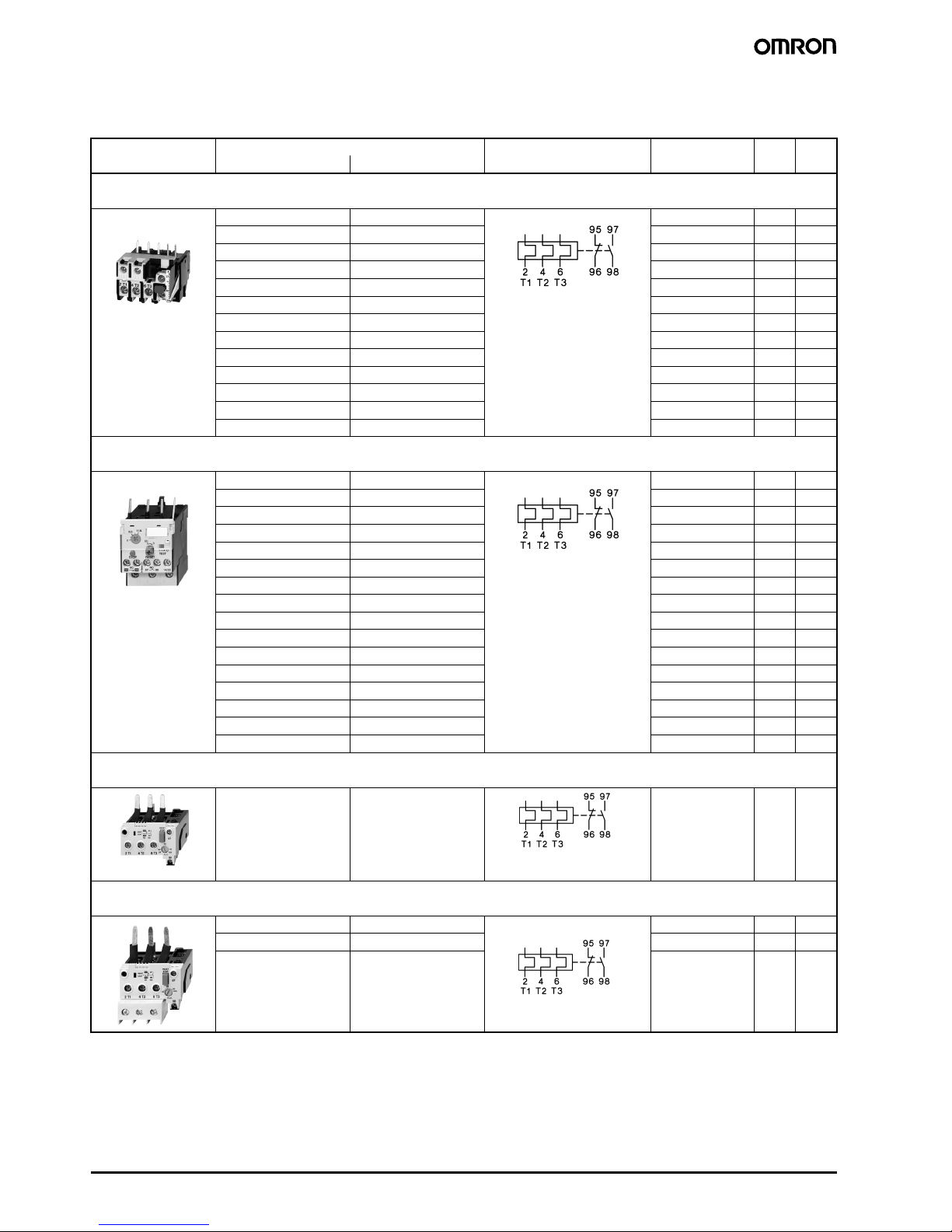
Setting Range Tripping time(in seconds) depending on the mul-
tiple of the current setting from cold condition (tol-
erance ±20% of the tripping time)
IA/INIA/INIA/INIA/INIA/INIA/IN
AA34567,28
J7TKN-A-...
0,12 - 0,18 18,5 10,4 7,2 5,5 4,3 3,6
0,18 - 0,27 16,7 9,8 6,5 5 4,1 3,5
0,27 - 0,4 19,4 12,1 8,2 5,9 4,9 4,2
0,4 - 0,6 18,7 11,2 8 6 4,9 4,1
0,6 - 0,9 19,7 11,6 8,1 6,1 4,9 4,2
0,8 - 1,2 22,9 13,6 10 7,3 6 5,2
1,2 - 1,8 22,2 13,2 9,2 7,6 5,8 5,3
1,8 - 2,7 23 13,7 9,3 7,6 5,7 5,1
2,7 - 424 14,4 9,9 7,8 5,9 5,1
4-624,7 13,8 9,9 7,3 5,6 4,8
6-922 13,4 8 5,7 4,1 3,5
8-11 17,4 9,2 5,9 4,1 2,9 2,3
10 - 14 26,4 12,9 7,6 5,2 3,5 2,8
J7TKN-B-...
0,12 - 0,18 16,1 9,6 6,8 5,3 4,2 3,7
0,18 - 0,27 16,6 9,7 6,7 5,2 4,1 3,6
0,27 - 0,4 19,4 11,4 7,9 6,1 4,7 4,2
0,4 - 0,6 18,7 10,9 7,6 5,9 4,6 4,0
0,6 - 0,9 19,2 11,2 7,7 5,9 4,6 4,1
0,8 - 1,2 20,8 12,3 8,5 6,6 5,2 4,6
1,2 - 1,8 25,5 14,1 9,8 7,6 5,9 5,2
1,8 - 2,7 26,6 15,6 10,9 8,3 6,5 5,7
2,7 - 422,7 13,6 9,5 7,4 5,8 5,1
4-622,2 13,3 9,3 7,1 5,6 4,9
6-920,4 11,9 8,2 6,1 4,7 4,0
8-11 20,9 11,8 7,9 5,7 4,3 3,5
10 - 14 21,3 11,7 7,4 5,1 3,7 3,0
13 - 18 21,2 12,1 8,0 6,2 4,6 4,1
17 - 24 20,4 12 8,6 6,3 4,5 3,7
23 - 32 20,2 10,2 6,7 4,7 3,4 2,8
J7TKN-C-42
28 - 42 25,2 13,3 8 5,5 4 3,1
J7TKN-D-...
40 - 52 18,3 9,2 5,6 3,9 2,8 2,2
52 - 65 17,8 8,7 5,2 3,4 2,5 1,9
60 - 74 19,5 13,5 11 10 9,5 8,5
J7TKN-E-...
60 - 90 19,5 13,5 11 10 9,5 8,5
80 - 120 18 11 10 9 8,5 8
J7TKN-F-... ssssss
100 - 150 34 26 24 20,5 19 18
140 - 210 30 24 21 18,5 17 16
Typical tripping
curve for overload
relay J7TKN-A
Minimum values of
tEtime (motor)
acc. to EN50019
ratio IA/IN

Thermal Overload Relay J7TKN 59
Fuses for J7TKN-A; J7TKN-B; J7TKN-C; J7TKN-D; J7TKN-E; J7TKN-F
Tripping Characteristics for J7TKN-A, J7TKN-B, J7TKN-C, J7TKN-D
Detailed tripping times for each range see table page 58
Type Setting Range Max. Fuse Size According to Coordination-
type
Fuse UL Fuse UL
(SCCR)
"2"*1
*1) Coordination-type according to IEC 947-4-1:
„2“: Light contact welding accepted. Thermal overload relay must not be damaged.
„1“: Welding of contactor and damage of the thermal overload relay allowed.
"1"*1 Short
Circuit
Current
Rating
DOL Star Delta quick slow,
gL(gG)
slow,
gL(gG)
aM
AA AAAAAkA
J7TKN-A
J7TKN-B
0.12 - 0.18 -0.5
*2
*2) Miniature fuse
0.5*2 25 - 15 5
0.18 - 0.27 -1.0
*2 1.0*2 25 - 15 5
0.27 - 0.4 -2225-155
0.4 - 0.6 -2225-155
0.6 - 0.9 -4425-155
0.8 - 1.2 -44252155
1.2 - 1.8 -66252155
1.8 - 2.7 - 101025 415 5
2.7 - 4- 161025 415 5
4-67 - 10.5 20 16 25 6 15 5
6-910.5 - 15.5 35 25 35 10 25 5
8-11 14-193525351630 5
10 - 14 18-245035631640 5
13 - 18 23-315035632050 5
17 - 24 30-416350632560 5
23 - 32 40-558063803570 5
J7TKN-C 28 - 42 48 - 73 100 80 150 50 110 5
J7TKN-D 40 - 52 70 - 90 160 100 150 63 200 5
52 - 65 90 - 112 160 125 150 80 250 10
60 - 74 104 - 128 160 125 150 80 250 10
J7TKN-E 60 - 90 104 - 156 For short circuit protecting overload relays
with current transformer use fuse accord-
ing to the contactor of the combination.
300 10
80 - 120 140 - 207 - -
J7TKN-F all ranges - -
with three-phase load with two-pole load
Tripping time
min. s
F.L.C. multiplication factor
Average value of
typical tolerance
curves from cold
condition
Proceeding from
service conditions
the times decrease
to 20-30% of the
characteristic values
Tripping time
min. s
K
Typical tolerance
curve from cold
condition
Proceeding from
service conditions
the times decrease
to 70-80% of the
characteristic values
K=Imax/Ie
Imax = max. phase current
Ie= max. scale value

60 Thermal Overload Relay J7TKN
Tripping Characteristics for J7TKN-E
Detailed tripping times for each range see table page 58
Tripping Characteristics for J7TKN-F
Detailed tripping times for each range see table page 58
with three-phase load with two-pole load
Tripping time
min. s
F.L.C. multiplication factor
Average value of
typical tolerance
curves from cold
condition
Proceeding from
service conditions
the times decrease
to 20-30% of the
characteristic values
Tripping time
min. s
K
Typical tolerance
curve from cold
condition
Proceeding from
service conditions
the times decrease
to 70-80% of the
characteristic values
K=Imax/Ie
Imax = max. phase current
Ie= max. scale value

Thermal Overload Relay J7TKN 61
Position of Terminals
Thermal Overload Relays
J7TKN-A J7TKN-B J7TKN-C; J7TKN-D
Data according to IEC 947-4-1, IEC 947-5-1, VDE 0660, EN 60947-4-1, EN 60947-5-1
Type J7TKN-A J7TKN-B J7TKN-C J7TKN-D J7TKN-E J7TKN-F
Rated insulation voltage Ui*1
*1) Suitable for: earthed-neutral systems, overvoltage category I to III, pollution degree 3 (standard-industry: Uimp = 4kV (at 440V), 6kV (at 690V).
Data for other conditions on request.
V~ 690 690 690 690 750 690
Permissible ambient temperature
operation open °C -25 to +60
storage °C -50 to +70
Trip class according to IEC 947-4-1 10A 10A 10A 10A 20 20
Cable cross-section
main connector solid or stranded mm² 0.75-6 +
0.75-2.5*2
*2) Maximum cable cross-section with prepared conductor
0.75-6 0,75-10 4-35*2 *3
*3) Without terminals, suitable for bushing one connector 70mm² (stranded) per phase
*4
*4) Busbar sets see accessories page 57
flexible mm² 0.75-4 +
0.5-2.5*2
1-4 0,75-6 6-25*2
flexible with multicore cable end mm² 0.5-2.5 +
0.5-1.5
0.75-4 0.75-6 4-25
Cables per clamp number 1+1 2 2 1
auxiliary connector solid mm² 0.75-2.5*2
flexible mm² 0.5-2.5*2
flexible with multicore cable end mm² 0.5-1.5
Cables per clamp number 2
Auxiliary contacts
Rated insulation voltage Ui*1
same potential V~ 690 690 690 690 690 690
different potential V~ 440 440 250 250 440 440
Utilization category AC15
Rated operational current Ie24V A 5 3 4*5
*5) Switching capacity of the start contact: AC15 300VA, max. 1.5A, DC13 (max. 220V) 30W, max. 1.5A
4*5 55
230V A 3 2 2.5 2.5 3 3
400V A 2 1 1.5 1.5 2 2
690V A 0.6 0.5 0.6 0.6 0.6 0.6
Utilization category DC13
Rated operational current Ie24V A 1.2 1 1.2 1.2 1.2 1.2
110V A 0.15 0.15 0.15 0.15 0.15 0.15
220V A 0.1 0.1 0.1 0.1 0.1 0.1
Short circuit protection (without welding 1kA)
highest fuse rating gL (gG) A 6 4 6666
Setting range A to 23 all 28-42 52-65 all -
Power loss per current path (max.)
minimum setting value W 1.1 1.1 1.3 2.9 1.1 -
maximum setting value W 2.3 2.3 3.3 4.5 2.5 -

62 Thermal Overload Relay J7TKN
Temperature Compensation
In case of higher ambient temperature use the following formula:
(Ambient temperature - 20) x 0.125 = correction factor in % of the
full load motor current
Example:
Ambient temperature 70°C, full load motor current 7A
(70 - 20) x 0.125 = 6.25%
Setting value: 7A + 6,25% = 7.44A
■Dimensions
Data according to CULUS
Type J7TKN-A J7TKN-B J7TKN-C J7TKN-D J7TKN-E
Rated insulation voltage V~ 600 600 600 600 600
Rated current A2332427485
Auxiliary contacts
Rated voltage
same potential V AC 600 600 600 600 600
different potential V~ 150 150 150 150 150
Switching capacity AC VA 500 500 600 600 600
ofaux.contacts A42444
J7KNA-09 + J7TKN-A
J7KNA-12 J7KN-10 + J7TKN-B
J7KN-14
J7KN-18
J7KN-22
J7KNG-10 D+ J7TKN-B
J7KNG-14 D
J7KNG-18 D
J7KNG-22 D
J7KN-24 + J7TKN-B
J7KN-32
J7KN-40

Thermal Overload Relay J7TKN 63
J7KNG-24 + J7TKN-B
J7KNG-32
J7KN-24 + J7TKN-C
J7KN-32
J7KN-40
J7KNG-40 + J7TKN-C J7KN-50 + J7TKN-D
J7KN-62
J7KN-74
J7KN-85 + J7TKN-E
J7KN-110
J7KN-151 + J7TKN-F
J7KN-176
45
35
80
M5
Ø4.5
312
M3.5
M3.5
149
108
64.5
6.5
86
104
55
34
104
86
6.5
M5
›4.5
35
45
67
23
5
72
68
M5
M3.5
M3.5
63
80
144
120

64 Thermal Overload Relay J7TKN
J7KN-200 + J7TKN-F
In the interest of product improvement, specifications are subject to change without notice.
ALL DIMENSIONS SHOWN ARE IN MILLIMETERS.
Cat. No. J07E-EN-01A
Do not use/install these products before having read the applicable precautions as listed in Cat. No. J09-EN-01
available from www.europe.omron.com or on request from OMRON local sales office.
Table of contents
Other Omron Relay manuals

Omron
Omron K8DT-PZ Series User manual

Omron
Omron G3PC User manual

Omron
Omron G3PE Series User manual

Omron
Omron K8AB-TH User manual

Omron
Omron G3PA-450B-VD-2 User manual

Omron
Omron K8AB-PA1 User manual

Omron
Omron K8DT-VW User manual

Omron
Omron G3PJ Series User manual

Omron
Omron MY4H User manual

Omron
Omron K8AK-VW3 User manual

Omron
Omron SR104P Operation manual

Omron
Omron G9SR User manual

Omron
Omron ZEN Use and care manual

Omron
Omron K8AB-PM Series User manual

Omron
Omron G9SX-ADA222-T Series User manual

Omron
Omron K8AK-AS User manual

Omron
Omron G7S User manual

Omron
Omron K8AB-VS Series User manual

Omron
Omron G9SA - User manual

Omron
Omron ZEN User manual