GE MultiLink ML600 User manual

MultiLink ML600
Ethernet Communications Switch
Instruction Manual
Firmware Revision 1.0.x
Manual P/N: 1601-0222-A2
Manual Order Code: GEK-113040A
Copyright © 2006 GE Multilin
ISO9001:2000
G
E
M
U
L
T
I
L
I
N
R
E
G
I
S
T
E
R
E
D
GE Multilin's Quality
Management System is
registered to ISO9001:2000
QMI # 005094
UL # A3775
GE Consumer & Industrial
GE Multilin
215 Anderson Avenue, Markham, Ontario
Canada L6E 1B3
Tel: (905) 294-6222 Fax: (905) 201-2098
Internet: http://www.GEmultilin.com
*1601-0222-A2*

These instructions do not purport to cover all details or variations in equipment nor provide
for every possible contingency to be met in connection with installation, operation, or
maintenance. Should further information be desired or should particular problems arise
which are not covered sufficiently for the purchaser’s purpose, the matter should be referred
to the General Electric Company.
To the extent required the products described herein meet applicable ANSI, IEEE, and NEMA
standards; but no such assurance is given with respect to local codes and ordinances
because they vary greatly.
© 2006 GE Multilin Incorporated. All rights reserved.
GE Multilin Multilink ML600 instruction manual for revision 1.0.x.
Multilink ML600 is a registered trademark of GE Multilin Inc.
The contents of this manual are the property of GE Multilin Inc. This documentation is
furnished on license and may not be reproduced in whole or in part without the permission
of GE Multilin. The content of this manual is for informational use only and is subject to
change without notice.
Part numbers contained in this manual are subject to change without notice, and should
therefore be verified by GE Multilin before ordering.
Part number: 1601-0222-A2 (November 2006)

TOC TABLE OF CONTENTS
MULTILINK ML600 ETHERNET COMMUNICATIONS SWITCH – INSTRUCTION MANUAL TOC–I
Table of Contents
1: INTRODUCTION GETTING STARTED ............................................................................................................1-1
INSPECTING THE PACKAGE AND PRODUCT ...................................................................... 1-1
ORDERING ..........................................................................................................................1-2
ORDER CODES ..................................................................................................................... 1-2
SPECIFICATIONS ................................................................................................................1-3
TECHNICAL SPECIFICATIONS .............................................................................................. 1-3
ENVIRONMENTAL SPECIFICATIONS .................................................................................... 1-4
PHYSICAL SPECIFICATIONS ................................................................................................. 1-4
APPROVALS AND WARRANTY ............................................................................................ 1-4
2: PRODUCT
DESCRIPTION
OVERVIEW ...........................................................................................................................2-1
INTRODUCTION TO THE ML600 ........................................................................................ 2-1
DESIGN ASPECTS ................................................................................................................. 2-1
FEATURES AND BENEFITS ...............................................................................................2-3
FRAME BUFFERING AND LATENCY .................................................................................... 2-3
ADDITIONAL FEATURES AND BENEFITS ............................................................................ 2-3
APPLICATIONS ...................................................................................................................2-5
DESCRIPTION ........................................................................................................................ 2-5
WINDMILL APPLICATION .................................................................................................... 2-5
INDUSTRIAL NETWORKING APPLICATION ......................................................................... 2-6
TRANSPORTATION SURVEILLANCE SYSTEM ...................................................................... 2-6
3: INSTALLATION PREPARATION ....................................................................................................................3-1
LOCATING THE ML600 ...................................................................................................... 3-1
ELECTRICAL INSTALLATION ...........................................................................................3-2
POWER REQUIREMENTS ...................................................................................................... 3-2
CONNECTING DC POWER .................................................................................................. 3-2
CONNECTING ETHERNET MEDIA ..................................................................................3-3
DESCRIPTION ........................................................................................................................ 3-3
CONNECTING TWISTED PAIR ............................................................................................. 3-3
CONNECTING ST-TYPE FIBER OPTICS (TWIST-LOCK) ...................................................... 3-3
CONNECTING SC-TYPE FIBER OPTICS (SNAP-IN) ............................................................ 3-4
CONNECTING SINGLE-MODE FIBER OPTICS .................................................................... 3-4
4: OPERATION FUNCTIONALITY ................................................................................................................4-1
DUAL-SPEED AND SWITCHING FUNCTIONALITY ............................................................. 4-1
SWITCHING, FILTERING AND FORWARDING .................................................................... 4-1
ADDRESS LEARNING ............................................................................................................ 4-2
AUTO-CROSS (MDIX), AUTO-NEGOTIATION, AND SPEED SENSING ............................. 4-2
STATUS LEDS...................................................................................................................... 4-2
ALARM CONTACT ................................................................................................................. 4-2
POWER BUDGET CALCULATIONS WITH FIBER MEDIA .................................................... 4-3
TROUBLESHOOTING .........................................................................................................4-5
OVERVIEW ............................................................................................................................ 4-5
BEFORE CALLING FOR ASSISTANCE .................................................................................. 4-5
WHEN CALLING FOR ASSISTANCE .................................................................................... 4-5

TOC–II MULTILINK ML600 ETHERNET COMMUNICATIONS SWITCH – INSTRUCTION MANUAL
TABLE OF CONTENTS
5: MISCELLANEOUS REVISION HISTORY ...........................................................................................................5-1
RELEASE DATES ................................................................................................................... 5-1
CHANGES TO THE MANUAL ................................................................................................ 5-1
CONFORMANCE STATEMENTS ......................................................................................5-2
FCC RFI STATEMENT ......................................................................................................... 5-2
WARRANTY .........................................................................................................................5-3
INDEX

MULTILINK ML600 ETHERNET COMMUNICATIONS SWITCH – INSTRUCTION MANUAL 1–1
Multilink ML600
Ethernet Communications Switch
Chapter 1: Introduction
GE Consumer & Industrial
Multilin
Introduction
1.1 Getting Started
1.1.1 Inspecting the Package and Product
Examine the shipping container for obvious damage prior to installing this product; notify
the carrier of any damage that you believe occurred during shipment or delivery. Inspect
the contents of this package for any signs of damage and ensure that the items listed
below are included.
This package should contain:
• MultiLink ML600 Ethernet Switch
• External AC adapter (for ML600-AC-** units)
• Set of metal panel mounting clips and screws (2 each)
Remove the items from the shipping container. Be sure to keep the shipping container
should you need to re-ship the unit at a later date.
In the event there are items missing or damaged, contact the party from whom you
purchased the product. If the unit needs to be returned, please use the original shipping
container if possible. Refer to Troubleshooting on page 4–5, for specific return procedures.

1–2 MULTILINK ML600 ETHERNET COMMUNICATIONS SWITCH – INSTRUCTION MANUAL
INTRODUCTION CHAPTER 1: INTRODUCTION
1.2 Ordering
1.2.1 Order Codes
The following table illustrates the order codes for the MultiLink ML600 Ethernet Switch.
Table 1–1: ML600 order codes
ML600 – * – *
Base unit ML600 ||MultiLink ML600 Ethernet Switch
Port
mounting AC |External AC adapter
24 |24 V DC power supply
48 |48 V DC power supply
Modules B1 6 ×RJ45 10/100 Mb copper
B2 2 ×100Base-F ST mm fiber and 4 ×RJ45 10/100 Mb copper
B3 2 ×100Base-F SC mm fiber and 4 ×RJ45 10/100 Mb copper
B4 2 ×100Base-F SC sm fiber and 4 ×RJ45 10/100 Mb copper

CHAPTER 1: INTRODUCTION INTRODUCTION
MULTILINK ML600 ETHERNET COMMUNICATIONS SWITCH – INSTRUCTION MANUAL 1–3
1.3 Specifications
1.3.1 Technical Specifications
PERFORMANCE
Ethernet (10 Mb):.............................................14880 pps
Fast Ethernet (100 Mb):................................148,800 pps
Data rate:...........................................................10 Mbps and 100 Mbps
Path delay value: ............................................ 50 BT on all ports
LLL (Link Loss Learn): ....................................factory default activated on ports 1 and 2 (allow to flush
the internal address buffer, and qualify to use with STP
and RSTP for faster recovery in ring topology)
RELIABILITY
MTBF:....................................................................over 15 years, Telcordia (Bellcore) method
NETWORK STANDARDS AND COMPLIANCE
100 Mb: ...............................................................Ethernet IEEE 802.3u, 100Base-TX, 100Base-FX
10 Mb:..................................................................Ethernet IEEE 802.3, 10Base-T
Auto-sensing for speed:..............................IEEE 802.3u
PACKET-PROCESSING BETWEEN DOMAINS
Filter and forward rate: ...............................14880 pps maximum (at 10 Mbps)
148800 pps maximum (at 100 Mbps)
Processing type:..............................................store and forward, non-blocking
Auto-learning:..................................................2K address table
Address buffer age-out time: ..................300 seconds
Packet buffers memory:..............................128 KB, dynamically shared on all domains
Latency (not including packet time):
5 ms (100 to 10 Mbps)
15 ms (10 to 100 Mbps)
MAXIMUM ETHERNET SEGMENT (OR DOMAIN) LENGTHS
10Base-T (Unshielded twisted pair): .............100 m (328 ft.)
100Base-TX (CAT 5 UTP): .....................................100 m (328 ft.)
100Base-FX, half-duplex (multi-mode): ......412 m (1350 ft.)
100Base-FX, full-duplex (multi-mode): ........2 km (6562 ft.)
100Base-FX, half-duplex (single-mode): ....412 m (1350 ft.)
100Base-FX, full-duplex (single-mode): ......18+ km
PORT CONNECTORS
RJ45 ports:.........................................................100Base-TX and 10Base-T with auto-cross (MDIX);
shielded 8-pin female connectors for shielded (STP) and
unshielded (UTP) CAT. 3, 4, and 5 cable
Fiber ports: ........................................................100Base-FX with multi-mode SC or ST, or single mode SC
connectors (factory settings default to full-duplex)
LED INDICATORS
POWER: ...............................................................steady ON when power applied
10/100:................................................................steady ON for 100 Mbps;
OFF for 10 Mbps (copper ports only)
LK/ACT:................................................................steady ON for LINK (LK) with no traffic;
BLINKING indicates port is transmitting/receiving (ACT)
F/H:........................................................................steady ON for full-duplex;
OFF for half-duplex (fiber port only)

1–4 MULTILINK ML600 ETHERNET COMMUNICATIONS SWITCH – INSTRUCTION MANUAL
INTRODUCTION CHAPTER 1: INTRODUCTION
ALARM RELAY
Internal 60 VA relay contact: ...................open for power off
closed for power on (hardware).
POWER SUPPLY
These products are to be supplied by a listed, direct plug-in power unit, marked “Class 2”, or a
listed ITE power supply, marked “LPS”, which has suitably rated output voltage (i.e. 24 or
48 V DC), and suitably rated output current (i.e. 100 to 500 mA). When connected to a 48 V DC
centralized source, these products shall be provided with a listed 5 A DC fuse in the supply
circuit.
Input (DC units):...............................................10 to 36 V DC for 24 V DC unit
30 to 60 V DC for 48 V DC unit
Input (AC units).................................................6 ft. AC power cord to IEC 320 connector on 100 to
240 V AC at 47 to 63 Hz external power adapter (output
of 12 V DC, 1.25 A)
Power consumption:.....................................7.0 W typical, 9 W maximum
1.3.2 Environmental Specifications
OPERATING ENVIRONMENT
Ambient temperature: .................................long term per agency tests (UL): –13 to 140°F (–25 to
60°C)
short term per IEC type tests: –40 to 149°F (–40 to 85°C)
Storage temperature: –40 to 160°F (–40 to 85°C)
Ambient relative humidity: ........................5% to 95% (non-condensing)
Cold start:...........................................................to –20°C
Altitude:...............................................................–200 to 5000 ft. (–60 to 1520 m)
NEBS:....................................................................NEBS compliance, including vibration, shock, and altitude
1.3.3 Physical Specifications
PACKAGING)
Enclosure: .........................................................rugged sheet metal (steel)
Dimensions:.......................................................3.7 in. ×3.0 in. ×1.7 in. (H ×W ×D)
9.4 cm ×7.6 cm ×4.3 cm (H ×W ×D)
Weight:................................................................13 oz. (370 g) for unit
5.8 oz. (165 g) for AC adapter
1.3.4 Approvals and Warranty
APPROVALS
UL:..........................................................................UL listed (UL60950), cUL, CE;
FCC:.......................................................................emissions meet FCC part 15 class A
NEBS:....................................................................level 3
ETSI:.......................................................................certified for carrier central offices
IEEE: ......................................................................IEEE P1613 environmental standard for electric power
substations
IEC:.........................................................................IEC61850 EMC and operating conditions class C for
power substations

CHAPTER 1: INTRODUCTION INTRODUCTION
MULTILINK ML600 ETHERNET COMMUNICATIONS SWITCH – INSTRUCTION MANUAL 1–5
WARRANTY
24 months from date of shipment
Manufactured in USA
GE Multilin reserves the right to change specifications, performance, characteristics, and/or
model offerings without notice.

1–6 MULTILINK ML600 ETHERNET COMMUNICATIONS SWITCH – INSTRUCTION MANUAL
INTRODUCTION CHAPTER 1: INTRODUCTION

MULTILINK ML600 ETHERNET COMMUNICATIONS SWITCH – INSTRUCTION MANUAL 2–1
Multilink ML600
Ethernet Communications Switch
Chapter 2: Product Description
GE Consumer & Industrial
Multilin
Product Description
2.1 Overview
2.1.1 Introduction to the ML600
The MultiLink ML600 Ethernet Switch is designed as an Ethernet edge solution in heavy-
duty industrial, military, and un-controlled temperature applications, as well as an
economical solution for the growing requirements of managed networks. The ML600
series, a six-port versatile family of compact edge switches, loaded with factory
configurable fiber and AC/DC power options, alarm terminal block, and innovative
packaging is ready to serve the needs of edge-of-the network applications.
The ML600 switches have a wide breadth of port configurability and fiber port type
options: six 10/100 copper ports or four 10/100 copper ports and two 100 Mb fiber ports.
The ML600 is a heavy-duty switch with extended temperature operation ranges for
hardened factory-floor applications. The breadth of models and selection of fiber ports
offers the best price-to-value ratio for each user and installation. The compact package is
ideal for network edge installations, and can be DIN-rail mounted to suit any application.
The MultiLink ML600 switches include a Link Loss Learn™ (LLL) feature to qualify for
redundant and self-healing managed network structures. The LLL feature allows the
ML600 switches to flush internal address buffers in milliseconds to permit quick changes in
LAN packets flow, allowing the reconfiguration signal to pass down the line to other ring
switches in the redundant structure for faster recovery. The ML600 switches, combined
with other MultiLink managed switches running STP/RSTP, can often provide high
availability redundant LANs at economical cost.
2.1.2 Design Aspects
The MultiLink ML600 Ethernet Switch is designed for factory floor applications. The ML600
models are built with high-grade components and constructed using special thermal
techniques and a metal case for heavy duty industrial jobs. In addition to a hardened AC
power option and jack, terminals for internal DC power are available for 24 or 48 V DC. The

2–2 MULTILINK ML600 ETHERNET COMMUNICATIONS SWITCH – INSTRUCTION MANUAL
PRODUCT DESCRIPTION CHAPTER 2: PRODUCT DESCRIPTION
unit has an ambient temperature rating of –25 to 60°C is for industrial use. No internal air
flow is required for cooling, providing resistance to dust, dirt, moisture, smoke, and insects.
Mounting options include stand-alone panel-mounting, DIN-Rail, or rack-mount tray.
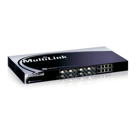
FIGURE 2–1: MultiLink ML600 switch
The ML600 includes a hardware operated alarm terminal block for providing extra
reliability to the unit. The Alarm feature allows the ML600 user to be aware and monitor
any internal power failure. Refer to Alarm Contact on page 4–2 for additional details.
The front of the unit contains one of the following port combinations:
• six 10/100 Mb copper ports
• four 10/100 Mb copper ports and two 100 Mb fiber ports
The RJ45 ports support auto-cross (MDIX) operation under auto-negotiation mode only.
The ML600 provides switching among the four 10/100 auto-negotiating copper ports and
two 100Mb fiber ports, which may be multi-mode SC or ST, or single-mode SC. The ML600
fiber options and temperature ratings provide many networking options and solutions in a
very small footprint.
Two sets of LEDs indicate the port operating status. These are located on the top and front
for viewing advantage while rack-mounted. Link and Activity (LK/ACT) LEDs indicate that
the media cables are connected correctly and indicate network traffic by blinking. The LK/
ACT LEDs are repeated on the front as 1 to 6 (port 1 to port 6), and on the side as LA1 to
LA6. Another set of LEDs on the front (10/100 and F/H) indicate the data rate and duplex
mode for ports 1 and 2. The 10/100 LED indicates the speed for copper ports, whereas the
F/H LED indicates full and half-duplex for fiber ports only.
There is also a power LED to indicate when the unit is turned ON. The fiber ports on the
ML600 are multi-mode or single-mode with an SC or ST connector.
The external DC connector and/or “jack” and the internal DC input terminal is provided on
the rear of the unit.

CHAPTER 2: PRODUCT DESCRIPTION PRODUCT DESCRIPTION
MULTILINK ML600 ETHERNET COMMUNICATIONS SWITCH – INSTRUCTION MANUAL 2–3
2.2 Features and Benefits
2.2.1 Frame Buffering and Latency
The ML600 is store-and-forward switch. Each frame (or packet) is loaded into the switch
memory and inspected before forwarding can occur. This technique ensures that all
forwarded frames are of a valid length and have the correct CRC (i.e., they are good
packets). This eliminates propagation of bad packets, enabling all of the available
bandwidth to be used for valid information.
While other switching technologies such as “cut-through” or “express” impose minimal
frame latency, they also permit bad frames to propagate to the Ethernet network. The
“cut-through” technique permits collision fragment frames, which are a result of late
collisions, to be forwarded – which add to the network traffic. There is no way to filter
frames with a bad CRC (the entire frame must be present in order for CRC to be calculated).
Since collisions and bad packets are more likely when traffic is heavy, store-and-forward
switch technology enables more bandwidth to be available for good packets when the
traffic load is greatest.
To minimize the possibility of dropping frames on congested ports, each ML600
dynamically allocates buffer space from a 128 KB memory pool, ensuring that heavily used
ports receive very large buffer space for packet storage (many other switches have their
packet buffer storage space divided evenly across all ports, resulting in a small, fixed
number of packets to be stored per port; when the port buffer fills up, dropped packets
result). This dynamic buffer allocation provides the capability for the maximum resources
of the ML600 to be applied to all traffic loads, even when the traffic activity is unbalanced
across the ports. Since the traffic on an operating network is constantly varying in packet
density per port and in aggregate density, the ML600 switches are constantly adapting
internally to provide maximum network performance with the least dropped packets.
When the ML600 detects that its free buffer queue space is low, it sends industry standard
(full-duplex only) PAUSE packets out to the devices sending packets to cause “flow control”.
This tells the sending devices to temporarily stop sending traffic, which allows a traffic
catch-up to occur without dropping packets. Then, normal packet buffering and
processing resumes. This flow-control sequence occurs in a small fraction of a second and
is transparent to an observer.
Another feature implemented in the ML600 is a collision-based flow-control mechanism
(when operating at half-duplex only). When the ML600 detects that its free buffer queue
space is low, it prevents more frames from entering by forcing a collision signal on all
receiving half-duplex ports in order to stop incoming traffic.
The latency (the time the frame spends in the switch before it is sent along or forwarded to
its destination) of the ML600 varies with the port-speed types. The length of the frame is
variable as it is with all store-and-forward switches. For 10 Mb-to-10 Mb, 10 Mb-to-100 Mb
or 100 Mb-to-10 Mb forwarding, the latency is 15 μs plus the packet time of 10 Mb. For
100 Mb-to-100 Mb forwarding, the latency is 5 μs plus the packet time of 100 Mb.
2.2.2 Additional Features and Benefits
•Full 10 or 100 Mb switching services for high performance Ethernet: The ML600
provides fast Ethernet switching on all ports. They perform high speed filter/forward
operations on the traffic, giving each port segment a full 10 Mb (or 100 Mb) of
bandwidth.
•Reduces network costs and provide an economical solution: The ML600 offers the
ideal solution to efficiently and inexpensively connect a twisted-pair and fiber network
with 10 or 100 Mb and expand in a convenient and economical way.

2–4 MULTILINK ML600 ETHERNET COMMUNICATIONS SWITCH – INSTRUCTION MANUAL
PRODUCT DESCRIPTION CHAPTER 2: PRODUCT DESCRIPTION
•"Plug and play" installation and operation is transparent to software: The ML600
operates as a hardware switch, only forwarding packets from each domain that are
required on the other domains. Internal address tables are self-learning, enabling
users to change port connections or 10/100 domains without affecting operations.
•Two sets of LEDs for viewing status from any angle: Each ML600 is equipped with
two sets (front and side) of LEDs to provide status information when viewed at almost
any angle or mounting arrangement.
•Rugged metal case: The industrial grade ML600 has a robust design and is packaged
in a rugged metal enclosure to ensure high reliability and durability in industrial
applications.
•Efficient compact design for all purpose mounting: The ML600 features a compact
steel case with an external AC or DC power supply. The ML600 can be installed in small
spaces in cabinets, on table tops, in racks, walls, or DIN-Rail mounted and in trays.
•MDIX ports to eliminate cross-over cable while cascading: All ML600 switches
feature MDIX (auto-cross), which allows cascading with other switch hubs or media
edges supporting auto-negotiation, without using the cross-over cable.
•Hardware operated alarm terminal block: The alarm contact enables monitoring for
internal power failure, and provides extra reliability to the ML600.
•Link Loss Learn feature for faster recovery in redundant managed network: The LLL
feature qualifies the edge switches to actively work along with redundant network
structure and allow a faster recovery during ring break.

CHAPTER 2: PRODUCT DESCRIPTION PRODUCT DESCRIPTION
MULTILINK ML600 ETHERNET COMMUNICATIONS SWITCH – INSTRUCTION MANUAL 2–5
2.3 Applications
2.3.1 Description
The MultiLink ML600 Ethernet Switch adapts well in almost any environment, enabling
quick network scalability and and cost effectively. The edge-of-the-network connectivity
solutions offered by the ML600 provides convenient, economical, and reliable solutions as
well as an active role on the managed redundant network setup for faster recovery. The
compact ML600 assists fast expanding network requirements by providing edge support
and reliability to the managed redundant network. The dual-speed and dual-media
functions support a mixed environment of 10 and 100Mbps and users with copper and
fiber media. The switched full duplex fiber port also provides high bandwidth and longer
distance support. The up-link feature of 100 Mb fiber on ports 1 and 2 enable easy
expansion for the on-going demand of Ethernet networks. The 10/100 Mbps auto-
negotiating MDIX copper ports and the breadth of 100 Mbps fiber ports enable easy
interfacing with existing cable plant and equipment.
The rugged case provides extra support in the harshest industrial environments. The Link-
Loss-Learn feature to provides extra reliability to the redundant network and an
economical solution for faster recovery during a ring break.
2.3.2 Windmill Application
In this example, the central control and monitoring center station is required to collect
monitoring data from various windmills or send control commands to various windmills.
This need can be easily met using the economical MultiLink ML600 Ethernet Switch.
Additional functionality includes the ability to transfer data across large distances with
multi- or single-mode fiber while securing the LAN from EMI and wire tapping.
The ML600’s six ports in a small, reliable enclosure provide an effective solution to for
transferring real-time transactions from the windmill to the storage device in the control
room. The easily deployable through DIN-rail option and the dual power source of flexibility
along with flavor of fiber option for distance, the ML600 easily meets all the requirements
of windmill. The ML600 not only provides a reliable solution but also reduces operational
costs significantly.
FIGURE 2–2: Windmill application

2–6 MULTILINK ML600 ETHERNET COMMUNICATIONS SWITCH – INSTRUCTION MANUAL
PRODUCT DESCRIPTION CHAPTER 2: PRODUCT DESCRIPTION
2.3.3 Industrial Networking Application
In this industrial networking application, new PLC units are deployed on a network
expansion. Each PLC requires one (or two for redundancy) Ethernet ports to carry status
and control data to the control center. The ML600 provides a good solution with its multiple
options and hardened features. The two fiber ports are ideal for secure data
communications over long distances. Built with high-grade components, efficient cooling
techniques and no openings for dirt, the ML600 switches provide a very effective solution
for this need.
FIGURE 2–3: Network with multiple subnets example
2.3.4 Transportation Surveillance System
In this example, the MultiLink ML600 Ethernet Switch is deployed to serve as a secure
corporate or transportation surveillance system. CCTV cameras may be spread out over
many miles in temperature un-controlled locations and with pan, tilt and zoom (PTZ)
controlled through an Ethernet copper port. The ML600 provides two fiber segments for
secure long distance (2 to 40km) communication while being installed in temperature un-
controlled cabinets and allowing for AC or DC power options. The four copper ports at the
remote location provides access for other Ethernet equipment such as motion detectors or
will act as a test port for maintenance personnel with up-link for access to a central LAN
and central file servers.
The ideally suited ML600 with its diversified features, premium rated approvals and cost-
effective solution, make an ideal choice in many outdoor environments.

CHAPTER 2: PRODUCT DESCRIPTION PRODUCT DESCRIPTION
MULTILINK ML600 ETHERNET COMMUNICATIONS SWITCH – INSTRUCTION MANUAL 2–7
FIGURE 2–4: Transportation surveillance application

2–8 MULTILINK ML600 ETHERNET COMMUNICATIONS SWITCH – INSTRUCTION MANUAL
PRODUCT DESCRIPTION CHAPTER 2: PRODUCT DESCRIPTION

MULTILINK ML600 ETHERNET COMMUNICATIONS SWITCH – INSTRUCTION MANUAL 3–1
Multilink ML600
Ethernet Communications Switch
Chapter 3: Installation
GE Consumer & Industrial
Multilin
Instal lati on
3.1 Preparation
3.1.1 Locating the ML600
The MultiLink ML600 Ethernet Switch operates in transparent half and full-duplex mode.
The store and forward switch takes care of network traffic and can be used as a useful,
economical tool to expand an existing network.
The compact and lightweight design of the ML600 allows it to be easily installed in almost
any location. A velcro strip may be used for mounting the unit on a vertical surface such as
a wall or cabinet, or for securing the unit on a table-top or shelf. Alternatively, metal
mounting clips and screws are included for a rugged and secure mounting in any
orientation.
Installation of the ML600 is a simple procedure. The installation location is dependent upon
the physical layout of the Ethernet network and associated cabling. Ensure the unit is
installed in a location that is easily accessible to an AC power outlet or the appropriate DC
source and where cooling is not inhibited. The green Power (PWR) LED must turn ON when
power is applied.

3–2 MULTILINK ML600 ETHERNET COMMUNICATIONS SWITCH – INSTRUCTION MANUAL
INSTALLATION CHAPTER 3: INSTALLATION
3.2 Electrical Installation
3.2.1 Power Requirements
The MultiLink ML600 Ethernet Switch is power-efficient and can work DC power or an
external AC power supply. The AC adapter input jack has a 2.5 mm plug, center positive,
with a 6 foot length of cord. Refer to Technical Specifications on page 1–3 for additional
details.
The ML600 is designed to be used with UL listed Class II power supplies.
The DC power option has a built-in terminal block for positive, negative, and ground. Detail
specifications on the 24 and 48 V DC options is available in Technical Specifications on
page 1–3.
When connected to a 48 V DC centralized source, the ML600 should only be installed only
in restricted access areas (dedicated equipment rooms, electrical closets or the like).
3.2.2 Connecting DC Power
The DC terminal block is located on the rear of the unit and is equipped with three (3)
screw-down lead posts. The power terminals are identified as positive (+) and negative (–),
and they are floating inside the unit so that either of the terminals may be grounded. The
chassis is “earth” or ground (GND).
Figure 3-1: DC power terminals
The connection procedure is straightforward. Simply insert the DC leads to the ML600
power terminals, positive (+) and negative (–) screws. The use of ground (GND) optional; it
connects to the ML600 chassis. Ensure that each lead is securely tightened from the top.
Always use a voltmeter to measure the voltage of the incoming power supply and
determine the positive or negative potential lead. The more positive potential lead will
connect to the post labeled “+ve” and the rest to the “–ve”. The ground can be hooked up
last
When power is applied, the green PWR LED will illuminate.
NOTE
NOTE
Table of contents
Other GE Switch manuals

GE
GE 15132 User manual

GE
GE MultiLink ML810 User manual

GE
GE In-wall WirelessSmart Switch User manual

GE
GE 15350 User manual

GE
GE BreakMaster Instruction Manual

GE
GE NETernity CP921RC-30X Quick user guide

GE
GE C-Start User manual

GE
GE EntelliGuard G Technical Document

GE
GE DS-242-POE Assembly instructions

GE
GE 28169 User manual