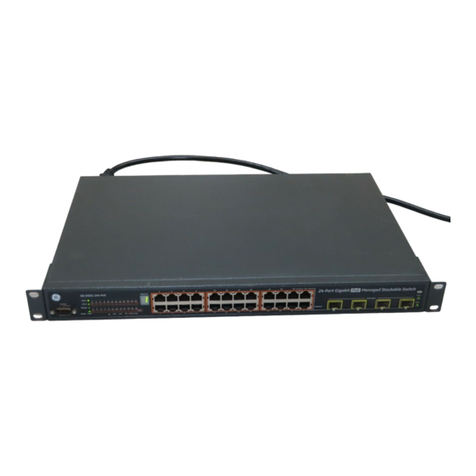
GE GLM064 User manual

GE
Automation & Controls
For Public Disclosure
Programmable Control Products
PACSystems* Ethernet Switch GLM Series User Manual
GFK-3030
PACSystems* PROFINET
Managed Industrial
Ethernet Switches
User Manual
GFK-3030
December 2017

Legal Information
Warnings, Cautions, and Notes as Used in this Publication GFL-002
Warning
Warning notices are used in this publication to emphasize that hazardous voltages,
currents, temperatures, or other conditions that could cause personal injury exist in
this equipment or may be associated with its use.
In situations where inattention could cause either personal injury or damage to
equipment, a Warning notice is used.
Caution
Caution notices are used where equipment might be damaged if care is not taken.
Note: Notes merely call attention to information that is especially significant to understanding
and operating the equipment.
These instructions do not purport to cover all details or variations in equipment, nor to provide for every
possible contingency to be met during installation, operation, and maintenance. The information is supplied
for informational purposes only, and GE makes no warranty as to the accuracy of the information included
herein. Changes, modifications, and/or improvements to equipment and specifications are made periodically
and these changes may or may not be reflected herein. It is understood that GE may make changes,
modifications, or improvements to the equipment referenced herein or to the document itself at any time. This
document is intended for trained personnel familiar with the GE products referenced herein.
GE may have patents or pending patent applications covering subject matter in this document. The furnishing
of this document does not provide any license whatsoever to any of these patents.
GE PROVIDES THE FOLLOWING DOCUMENT AND THE INFORMATION INCLUDED THEREIN AS-IS AND WITHOUT
WARRANTY OF ANY KIND, EXPRESSED OR IMPLIED, INCLUDING BUT NOT LIMITED TO ANY IMPLIED STATUTORY
WARRANTY OF MERCHANTABILITY OR FITNESS FOR PARTICULAR PURPOSE.
* indicates a trademark of General Electric Company and/or its subsidiaries.
All other trademarks are the property of their respective owners.
©Copyright 2017 General Electric Company.
All Rights Reserved

Contact Information
If you purchased this product through an Authorized Channel Partner, please contact the seller directly.
General Contact Information
Online technical support and GlobalCare
www.geautomation.com/support
Additional information
www.geautomation.com
Solution Provider
Technical Support
If you have technical problems that cannot be resolved with the information in this manual, please contact us
by telephone or email, or on the web at www.geautomation.com/support
Americas
Phone
1-800-433-2682
International Americas Direct Dial
1-780-420-2010 (if toll free 800 option is unavailable)
Customer Care Email
Primary language of support
English
Europe, the Middle East, and Africa
Phone
+800-1-433-2682
EMEA Direct Dial
+420-296-183-331 (if toll free 800 option is unavailable or if
dialing from a mobile telephone)
Customer Care Email
digitalsupport.emea@ge.com
Primary languages of support
English, French, German, Italian, Czech, Spanish
Asia Pacific
Phone
+86-400-820-8208
+86-21-3877-7006 (India, Indonesia, and Pakistan)
Customer Care Email
Primary languages of support
Chinese, Japanese, English

GFK-3030 December 2017 i
Table of Contents
PACSystems* Ethernet Switch GLM Series User Manual GFK-3030
Table of Contents............................................................................................................................................................... i
Table of Figures................................................................................................................................................................ iv
Chapter 1 Introduction ................................................................................................................................................ 1
1.1 Revisions in this Manual ........................................................................................................................... 2
1.2 PACSystems Documentation ................................................................................................................... 2
Chapter 2 Overview ...................................................................................................................................................... 3
2.1 System Overview........................................................................................................................................ 3
IO-Devices on a PROFINET Network..................................................................................................................3
Ethernet Devices on an Ethernet Network.....................................................................................................4
GLM System Capabilities .........................................................................................................................................4
2.2 GLM Product Differentiation .................................................................................................................... 5
2.3 GLM Features .............................................................................................................................................. 5
2.4 GLM LEDS ..................................................................................................................................................... 6
Chapter 3 Installation .................................................................................................................................................. 7
3.1 Mounting...................................................................................................................................................... 7
DIN-Rail Mounting.......................................................................................................................................................7
Panel Mounting.............................................................................................................................................................8
3.2 Power Connection ...................................................................................................................................... 9
GLM Switch Current Draw.......................................................................................................................................9
3.3 Grounding.................................................................................................................................................. 10
3.4 Alarm Relay Output ................................................................................................................................. 11
3.5 Ethernet Connections.............................................................................................................................. 12
RJ45 Connections..................................................................................................................................................... 12
SFP Connections ....................................................................................................................................................... 13
3.6 LED Operation........................................................................................................................................... 14
3.7 System Reset............................................................................................................................................. 15
3.8 Console Connection ................................................................................................................................. 16

Contents
ii PACSystems PROFINET Managed Industrial Ethernet Switches User Manual GFK-3030
Chapter 4 Configuration............................................................................................................................................ 17
4.1 Import the GSDML file ............................................................................................................................. 18
4.2 Associating the IO-Device with its Controller .................................................................................... 21
4.3 PROFINET Cyclic I/O Data....................................................................................................................... 23
Slot 1: Device Status................................................................................................................................................24
Slot 2: Port Status......................................................................................................................................................24
Slot 3: Port Alarm & Port Settings & Status .................................................................................................25
Slot 4: MRP Group 1 Status ..................................................................................................................................27
Slot 5: MRP Group 2 Status ..................................................................................................................................28
Slot 6: Ring Group 1 Status ..................................................................................................................................29
Slot 7: MRE Group 1 Status ..................................................................................................................................29
Slot 8: MRE Group 2 Status ..................................................................................................................................29
4.4 PROFINET Acyclic I/O Data..................................................................................................................... 30
Acyclic Device Data –Subslot 0 .........................................................................................................................30
Acyclic Port Data –Subslot 1..............................................................................................................................32
Acyclic MRP Group 1 Data –Subslot 2 ..........................................................................................................33
Acyclic MRP Group 2 Data –Subslot 3 ..........................................................................................................33
Acyclic Ring Group 1 Data –Subslot 4 ..........................................................................................................34
Acyclic MRPe Group 1 Data –Subslot 5........................................................................................................35
Acyclic MRPe Group 2 Data –Subslot 6........................................................................................................35
4.5 Assigning Device Name and IP Address .............................................................................................. 36
4.6 MRP Settings for IO-Devices .................................................................................................................. 37
4.7 Download from PME to CPU ................................................................................................................... 38
4.8 Hot Standby CPU Redundancy Considerations.................................................................................. 38
4.9 Discovery Tool .......................................................................................................................................... 39
Chapter 5 Diagnostics................................................................................................................................................ 41
Setting up and Sensing Alarms .........................................................................................................................42
Power Alarm................................................................................................................................................................43
5.2 External Alarm Circuit............................................................................................................................. 44
Appendix A Command Language Interface (CLI) ........................................................................................................ 45
A-1 Operator Interface................................................................................................................................... 45
Login ................................................................................................................................................................................45
Connection Interface ..............................................................................................................................................45
Login Screen Description......................................................................................................................................45
Execution Modes.......................................................................................................................................................46

Getting help .................................................................................................................................................................46
Terminal Key Function ...........................................................................................................................................47
Notation Conventions.............................................................................................................................................47

Contents
GFK-3030 December 2017 iii
A-2 Summary of Commands Descriptions.................................................................................................. 48
A-3 Command Descriptions .......................................................................................................................... 49
Initialize Mode Commands.................................................................................................................................. 49
Enable Mode Commands..................................................................................................................................... 50
Configure Mode Commands............................................................................................................................... 71
VLAN Mode Commands ........................................................................................................................................ 91
Interface VLAN Mode Commands ................................................................................................................... 94
RingV2 Group Mode Commands...................................................................................................................... 97
Spanning Tree Commands.................................................................................................................................. 99
sFlow Configure Commands ............................................................................................................................103
SNMP Configure Commands............................................................................................................................105
Qos Function Commands...................................................................................................................................109
IGMP Functional Commands............................................................................................................................113
MVR Functional Commands .............................................................................................................................115
MLD Functional Commands .............................................................................................................................119
Loop-Protection Configure Commands......................................................................................................122
LLDP Configure Commands..............................................................................................................................123
RFC2544 Testing Configure Commands ....................................................................................................125
GVRP Configure Commands.............................................................................................................................127
Voice VLAN Configure Commands................................................................................................................128
Profile Alarm Commands ...................................................................................................................................129
Appendix B Supported Ethernet Commands .............................................................................................................131

Contents
iv PACSystems PROFINET Managed Industrial Ethernet Switches User Manual GFK-3030
Table of Figures
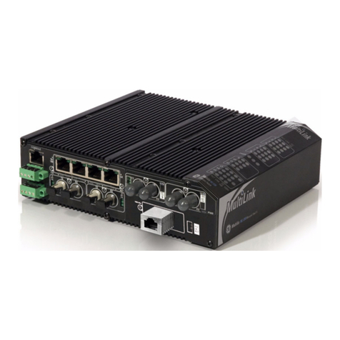
Figure 1: GLM064 ........................................................................................................................................................................................................1
Figure 2: GLM082 ........................................................................................................................................................................................................1
Figure 3: GLM104 ........................................................................................................................................................................................................1
Figure 4: Typical PROFINET System with GLM Switches..........................................................................................................................3
Figure 5: GLM Switch Bottom Panel...................................................................................................................................................................5
Figure 6: Front-Panel LEDs .....................................................................................................................................................................................6
Figure 7: DIN-Rail Mounting...................................................................................................................................................................................7
Figure 8: Panel-Mounting ........................................................................................................................................................................................8
Figure 9: Dual DC Power Input Connections..................................................................................................................................................9
Figure 10: Ground Connection...........................................................................................................................................................................10
Figure 11: Alarm Relay Output ..........................................................................................................................................................................11
Figure 12: RJ45 Pinout...........................................................................................................................................................................................12
Figure 13: Ports 1 & 2 Copper Connections ................................................................................................................................................12
Figure 14: Fiber-Optic Cable with LC Duplex Connectors ....................................................................................................................13
Figure 15: Attach Fiber-Optic Cables to Installed SFP Socket ............................................................................................................13
Figure 16: Console Port .........................................................................................................................................................................................16
Figure 17: Console Cable Wiring.......................................................................................................................................................................16
Figure 18: PME Toolchest Feature....................................................................................................................................................................18
Figure 19: Toolchest Data Types.......................................................................................................................................................................18
Figure 20: Select PROFINET Device..................................................................................................................................................................19
Figure 21: Import GSDML Command .............................................................................................................................................................19
Figure 22: Browse to Folder and Select GSDML file for Import .........................................................................................................20
Figure 23: Toolchest Displays Newly-Added Device...............................................................................................................................20
Figure 24: Add IO-Device to PROFINET Controller....................................................................................................................................21
Figure 25: Select IO-Device from PROFINET Device Catalog ..............................................................................................................21
Figure 26: IO-Device Installed Under PNC001 ...........................................................................................................................................22
Figure 27: Assign Starting %I & %Q References for Cyclic I/O Data ...............................................................................................23
Figure 28: Properties of IO-Device ...................................................................................................................................................................36
Figure 29: Inspector Form for IO-Device.......................................................................................................................................................36
Figure 30: Accessing the MRP Parameters of an IO-Device................................................................................................................37
Figure 31: Set up MRP Ring Ports.....................................................................................................................................................................37
Figure 32: MRP Group2 Data Tab.....................................................................................................................................................................37
Figure 33: Launch Discovery Tool ....................................................................................................................................................................39
Figure 34: Discovery Tool in Progress ............................................................................................................................................................39
Figure 35: Listing of all Detected Devices.....................................................................................................................................................40
Figure 36: GLM Switch Parameters Set in PME .........................................................................................................................................42
Figure 37: Set Port Alarm Active or Inactive Using PME .......................................................................................................................42
Figure 38: External Alarm Circuit......................................................................................................................................................................44
Figure 39: Login Constraints...............................................................................................................................................................................45
Figure 40: Telnet Login Screen...........................................................................................................................................................................46


GFK-3030 December 2017 1
Chapter 1 Introduction
Figure 1: GLM064
Figure 2: GLM082
Figure 3: GLM104
The PACSystems GLM series Industrial Ethernet Switches deliver high quality Ethernet operation over a wide
temperature range and can tolerate an extended power input range. These switches are ideal for harsh
environments and mission critical applications. They may be DIN-rail mounted or panel-mounted.
This document includes a product overview and covers installation, configuration, operation and diagnostics.

Chapter 1. Introduction
2 PACSystems PROFINET Managed Industrial Ethernet Switches User Manual GFK-3030
1.1 Revisions in this Manual
Rev
Date
Description
Dec-
2017
•Initial release.
1.2 PACSystems Documentation
PACSystems Manuals
PACSystems RX7i, RX3i and RSTi-EP CPU Reference Manual
GFK-2222
PACSystems RX7i, RX3i and RSTi-EP CPU Programmer’s Reference Manual
GFK-2950
PACSystems RX7i, RX3i and RSTi-EP TCP/IP Ethernet Communications User Manual
GFK-2224
PACSystems TCP/IP Ethernet Communications Station Manager User Manual
GFK-2225
PACSystems Memory Xchange Modules User’s Manual
GFK-2300
PACSystems Hot Standby CPU Redundancy User Manual
GFK-2308
Proficy Machine Edition Logic Developer Getting Started
GFK-1918
Proficy Process Systems Getting Started Guide
GFK-2487
PACSystems RXi, RX3i, RX7i and RSTi-EP Controller Secure Deployment Guide
GFK-2830
PACSystems RX3i & RSTi-EP PROFINET I/O Controller Manual
GFK-2571
RX3i Manuals
PACSystems RX3i System Manual
GFK-2314
PACSystems RX3i Ethernet Network Interface Unit User’s Manual
GFK-2439
PACSystems RX3i PROFINET Scanner Manual
GFK-2737
In addition to these manuals, datasheets and product update documents describe individual modules and
product revisions. The most recent PACSystems documentation is available on the GE Intelligent Platforms
support website http://geautomation.com/support.

GFK-3030 December 2017 3
Chapter 2 Overview
2.1 System Overview
IO-Devices on a PROFINET Network
GLM Switches are treated as PROFINET-IO devices. The host PLC will therefore use an embedded PROFINET
port or a PNC001 PROFINET IO-Controller Module. All physical connections use standard Ethernet connectors
(RJ45 or SFP).
Figure 4: Typical PROFINET System with GLM Switches

Chapter 2. Overview
4 PACSystems PROFINET Managed Industrial Ethernet Switches User Manual GFK-3030
Ethernet Devices on an Ethernet Network
The GLM switches contain a number of features which cannot be accessed over PROFINET, but are available
over Ethernet. The user may choose to install a separate Ethernet network for this purpose, or run both
PROFINET and Ethernet on the same physical network. Refer to Appendix B, Supported Ethernet Commands.
Caution
Care needs to be taken that connection to an Ethernet networks does not expose
the application to outside interference or monitoring, and does not impose heavy
traffic on the PROFINET network, which is intended to service IO-Devices in a timely
manner. Refer to the PACSystems RXi, RX3i, RX7i and RSTi-EP Controller Secure
Deployment Guide, GFK-2830.
Within the RX3i, the user may install an ETM001 module in a rack controlled by the host PLC CPU, or may use
an embedded Ethernet port within the CPU itself to provide the Ethernet features. .If none of the Ethernet-only
features will be used, no dedicated Ethernet function is required.
The following features, which are outside the scope of this manual, may be accessed over Ethernet, but may
not be accessed over PROFINET:
•Virtual LANs (VLANs)
•Access Control List Security (ACL)
•Quality of Service (QoS) features
•Internet Group Management Protocol (IGMP)
GLM System Capabilities
Function Name
System Max Value
VLAN ID
4096
VLAN Limitation
1024
Privilege Level of User
15
RMON Statistic Entry
65535
RMON Alarm Entry
65
RMON Event Entry
65535
IPMC Profile
64
IPMC Rule / Address Entry
128
ACE
256
ICMP Type / Code
255
MAC-based VLAN Entry
256
IP subnet-based VLAN Entry
128
Protocol-based VLAN Group
125
Voice VLAN OUI
16
QCE
256
IP Interface (for management)
8
IP Route (for management)
32
Security Access Management
16
MVR VLAN
4
MAC Learning table address
8k
IGMP Group
256

Chapter 2. Overview
GFK-3030 December 2017 5
2.2 GLM Product Differentiation
Product differentiation within the GLM Series of products lies in the number of standard RJ45 Ethernet
connections and Small Form-Factor Pluggable (SFP) ports offered, as follows:
Product
Number of RJ45 Ports
Number of SFP Ports
Appearance
IC086GLM064
6
4
Figure 1
IC086GLM082
8
2
Figure 2
IC086GLM104
10
4
Figure 3
Note that the final three digits of the GLM part numbers convey the information about the intrinsic port
configuration.
2.3 GLM Features
Each is a stand-alone Ethernet switch that may be mounted on a DIN-rail, or panel-mounted. Refer to Section
3.1.
Operating Temperature Range: -40°C to +75°C (-40°F to +167°F).
Each is equipped with the same bottom-panel (Figure 5), which includes a dual 12Vdc-58Vdc power input, a
ground stud, an alarm contact, a reset pushbutton and an RJ45 port suitable for attaching a console. Each of
these features is discussed in Chapter 3.
Figure 5: GLM Switch Bottom Panel

Chapter 2. Overview
6 PACSystems PROFINET Managed Industrial Ethernet Switches User Manual GFK-3030
2.4 GLM LEDS
Figure 6: Front-Panel LEDs
Each GLM Switch product is equipped with a common set of LEDs, as shown in Figure 6:
•One LED for each of the two permitted power supply inputs (P1 and P2)
•One LED for the Alarm Contact (ALM)
For each Ethernet port, there is an amber speed LED and a green Link Activity LED. The appearance is different
for the RJ45 ports (suitable for copper cables) versus the SFP connectors, as indicated in Figure 6.
LED Operation is detailed in Section 3.6.

GFK-3030 December 2017 7
Chapter 3 Installation
3.1 Mounting
The GLM switches may be DIN-rail mounted or panel-mounted.
DIN-Rail Mounting
Figure 7: DIN-Rail Mounting
1) Attach the DIN-Rail bracket to the mounting surface with the bracket and screws in the included
accessory kit.
2) Hook the top edge of the DIN-Rail latch attached to the GLM switch over the top edge of the DIN rail.
3) Push the bottom of the GLM unit towards the DIN Rail until the bottom latch snaps into place.

Chapter 3. Installation
8 PACSystems PROFINET Managed Industrial Ethernet Switches User Manual GFK-3030
Panel Mounting
Figure 8: Panel-Mounting
1) Prepare two pilot holes in the mounting surface 172mm apart, per Figure 8.
2) Attach the top and bottom panel-mounting plates to the rear of the GLM switch chassis using the
screws provided in the accessory kit.
3) Secure the GLM switch to the mounting surface with a pair of M4 machine screws.

Chapter 3. Installation
GFK-3030 December 2017 9
3.2 Power Connection
The 6-pin terminal block on the bottom panel contains connectors for two DC power inputs. Each is indicated
with polarity signs, as shown.
Figure 9: Dual DC Power Input Connections
The GLM Switch may be powered from one or both power inputs. The specified voltage range is 12Vdc–58Vdc.
The 6-pin terminal strip will accept AWG 28~14. The wire should be stripped back 6~7mm. The screw torque
limit is 2Nm.
The P1 and P2 LEDs on the front panel indicate the status of these two power supply inputs, as shown in
Section 3.6, LED Operation.
GLM Switch Current Draw
The maximum current draw at 24Vdc (nominal) for each of the devices is shown below:
Device
Max Current @ 24Vdc (nominal)
GLM064
580mA
GLM082
521mA
GLM104
709mA
Note: Each DC power input should be connected to a suitably-fused power supply.

Chapter 3. Installation
10 PACSystems PROFINET Managed Industrial Ethernet Switches User Manual GFK-3030
3.3 Grounding
Each GLM switch must be properly grounded for optimal performance. A ground screw (chassis ground) is
provided as part of the bottom panel, as shown below. Loosen the ground screw, insert the stripped end of the
ground strap, then tighten the ground screw to secure the ground strap in place. The other end of the ground
strap (which should be as short as possible) should be securely connected to earth ground.
Figure 10: Ground Connection

Chapter 3. Installation
GFK-3030 December 2017 11
3.4 Alarm Relay Output
The Alarm Relay Output is located on the two terminals in the center of the 6-pin terminal strip on the bottom
panel.
Figure 11: Alarm Relay Output
The Alarm Relay Output may be connected to an external device. It is a Normally Open Relay. The state of the
Alarm Relay is indicated on the ALM LED, as documented in Section 3.6, LED Operation.
Refer to Section 3.2 for wire size and stripping information.
Figure 38 diagrams a typical external alarm circuit.

Chapter 3. Installation
12 PACSystems PROFINET Managed Industrial Ethernet Switches User Manual GFK-3030
3.5 Ethernet Connections
Ethernet connections use either RJ45 (electrical) or mini-GBIC (optical) interfaces. All Ethernet connections are
located on the faceplate. Refer to Figure 1 through Figure 3.The number and type available for each product in
the GLM series is discussed in Section 2.1.3, GLM System Capabilities.
The activity and speed of each port is indicated separately, as documented in Section 3.6, LED Operation.
RJ45 Connections
GLM Switches use standard RJ45 connectors for their electrical interfaces. For example, on GLM082, Ports 1-8
are electrical only.
•To connect to a PC, use a straight-through or a cross-over Ethernet cable
•To connect the GLM Switch copper port to an Ethernet device, use UTP (Unshielded Twisted Pair) or
STP (Shielded Twisted Pair) Ethernet cables.
Figure 12: RJ45 Pinout
Pin
Assignment
1,2
T/Rx+, T/Rx-
3,6
T/Rx+, T/Rx-
4,5
T/Rx+, T/Rx-
7,8
T/Rx+, T/Rx-
Figure 13: Ports 1 & 2 Copper Connections

Chapter 3. Installation
GFK-3030 December 2017 13
SFP Connections
GLM Switches provide SFP connections using an optical (mini-GBIC) interface. For example, on GLM082, Ports
9 and 10 are SFP ports.
Figure 14: Fiber-Optic Cable with LC Duplex Connectors
Figure 15: Attach Fiber-Optic Cables to Installed SFP
Socket
Prepare a suitable SFP module and install it into the GLM optical port. Then connect the fiber optic cabling that
uses LC connectors (or SC connectors with the use of an optional SC-to-LC adapter) to the fiber optic socket.
Warning
Never attempt to view optical connectors that might be emitting laser energy.
Do not power up the laser product without first connecting the laser to the optical
fiber and properly installing the protective cover.
Laser light, which may cause damage to the eye, will be produced as soon as
power is applied to the laser source.
Warning
When a fiber optic connector is removed during installation, testing, or servicing, or
when an energized fiber is broken, there is a risk of injury to the eye. Exposure to
optical energy may be hazardous to the eye, depending on the laser output power.
The primary hazards of exposure to laser radiation from an optical-fiber
communication system are:
Damage to the eye by accidental exposure to a beam emitted by a laser
source.
Damage to the eye from viewing a connector attached to a broken fiber or an
energized fiber.
This manual suits for next models
5
Table of contents
Other GE Switch manuals

GE
GE GuardSwitch 300 Series User manual

GE
GE ZW4106 User manual

GE
GE DS-242-POE Assembly instructions

GE
GE BM-C303US5-04 User manual

GE
GE ZTS Series Installation guide

GE
GE GE-DSG-244 Assembly instructions

GE
GE Quirky+ User manual

GE
GE "ExecutiveSeries"USB2.0 HO97863 User manual

GE
GE EntelliGuard G Technical Document

GE
GE GLX+Q 1 1COM 16A 2M AST IR User manual
Popular Switch manuals by other brands

Dahua
Dahua DH-PFS4218-16GT-190 quick start guide

D-Link
D-Link DES-1018MP Quick installation guide

Belden
Belden HIRSCHMANN OCTOPUS OS3 user manual

StarTech.com
StarTech.com ST7202USBGB instruction manual

Mine Site Technologies
Mine Site Technologies NS50 user manual

Ubiquiti
Ubiquiti UniFi USW-Industral Quck Start Guide