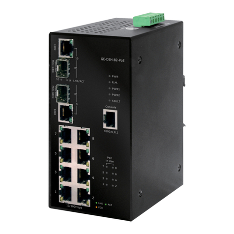
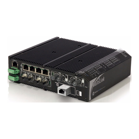
GE MultiLink ML810 User manual

MultiLink ML810
Managed Edge Switch
Instruction Manual
Firmware Revision 5.x
Manual P/N: 1601-0123-A2
Manual Order Code: GEK-113604A
Copyright © 2012 GE Digital Energy
GE Digital Energy
215 Anderson Avenue, Markham, Ontario
Canada L6E 1B3
Tel: (905) 294-6222 Fax: (905) 201-2098
Internet: http://www.gedigitalenergy.com
*1601-9107-A2*
IISO9001:2000
G
E
M
U
L
T
I
L
I
N
R
E
G
I
S
T
E
R
E
D
GE Digital Energy's Quality
Management System is
registered to ISO9001:2000
QMI # 005094
UL # A3775
Digital Energy

These instructions do not purport to cover all details or variations in equipment nor provide for every
possible contingency to be met in connection with installation, operation, or maintenance. Should further
information be desired or should particular problems arise which are not covered sufficiently for the
purchaser’s purpose, the matter should be referred to the General Electric Company.
To the extent required the products described herein meet applicable ANSI, IEEE, and NEMA standards; but
no such assurance is given with respect to local codes and ordinances because they vary greatly.
© 2012 GE Digital Energy Incorporated. All rights reserved.
GE Digital Energy A2 instruction manual for revision 5.x.
Multilink ML810 is a registered trademark of GE Digital Energy Inc.
NEBS is a trademark of Telcordia Technologies
The contents of this manual are the property of GE Digital Energy Inc. This documentation is furnished on
license and may not be reproduced in whole or in part without the permission of GE Digital Energy. The
content of this manual is for informational use only and is subject to change without notice.
Part numbers contained in this manual are subject to change without notice, and should therefore be
verified by GE Digital Energy before ordering.
Part number: 1601-0123-A2 (February 2012)
Federal Communications Commission
Radio Frequency Interference Statement
This equipment generates, uses and can radiate frequency energy and if not installed and used properly
in strict accordance with the manufacturer's instructions, may cause interference to radio
communication. It has been tested and found to comply with the limits for a Class A computing device in
accordance with the specifications in Subpart J of Part 15 of FCC rules, which are designed to provide
reasonable protection against such interference when operated in a commercial environment. Operation
of this equipment in a residential area is likely to cause interference, in which case the user, at their own
expense, will be required to take whatever measures may be required to correct the interference.
Canadian Emissions Statement
This Class A digital apparatus meets all requirements of the Canadian Interference-Causing Equipment
Regulations.
Cet appareil respecte toutes les exigences du Réglement sur le matériel du Canada. Cet appareil est
Classe A..
Electrical Safety requirements:
1. This product is to be installed Only in Restricted Access Areas (Dedicated Equipment Rooms, Electrical
Closets, or the like).
2. 48 V DC products shall be installed with a readily accessible disconnect device in the building
installation supply circuit to the product.
3. This product shall be provided with a maximum 10 A DC Listed fuse or circuit breaker in the supply
circuit when connected to a 48 V centralized DC source.
4. The external power supply for DC units shall be a Listed, Direct Plug In power unit, marked Class 2, or
Listed ITE Power Supply, marked LP, which has suitably rated output voltage (i.e. 24 V DC or 48 V DC)
and suitable rated output current.
5. Product does not contain user replaceable fuses. Any internal fuses can ONLY be replaced by GE
Digital Energy.

This product cannot be disposed of as unsorted municipal waste in the European
union. For proper recycling return this product to your supplier or a designated
collection point. For more information go to www.recyclethis.info .


TOC TABLE OF CONTENTS
MULTILINK ML810 MANAGED EDGE SWITCH – INSTRUCTION MANUAL TOC–1
Table of Contents
1: SPECIFICATIONS TECHNICAL SPECIFICATIONS ........................................................................... 1-1
ORDERING INFORMATION ................................................................................. 1-5
2: INTRODUCTION INSPECTING THE PACKAGE AND PRODUCT ................................................. 2-1
PRODUCT DESCRIPTION ..................................................................................... 2-2
PACKET PRIORITIZATION, 802.1PQOS ...............................................................................2-3
FRAME BUFFERING AND FLOW CONTROL ...........................................................................2-3
FEATURES AND BENEFITS ................................................................................. 2-4
APPLICATIONS ...................................................................................................... 2-6
3: INSTALLATION LOCATING MULTILINK ML810 SWITCHES ..................................................... 3-2
CONNECTING ETHERNET MEDIA .................................................................... 3-3
CONNECTING TWISTED PAIR (CAT3, CAT5, UTP OR STP) .............................................3-3
CONNECTING TWISTED PAIR (CAT5EOR BETTER, UTP OR STP) ....................................3-4
CONNECTING SINGLE-MODE FIBER OPTIC ..........................................................................3-4
GIGABIT SFP (SMALL FORM-FACTOR PLUGGABLE) TRANSCEIVERS .................................3-4
CONNECTING FIBER OPTIC CABLE TO SFP TRANSCEIVERS ..............................................3-5
DIN-RAIL MOUNTING THE MULTILINK ML810 ............................................. 3-6
MOUNTING DIMENSIONS FOR ML810 WITH METAL BRACKETS .......................................3-6
POWERING THE MULTILINK ML810 MANAGED EDGE SWITCH .............. 3-10
ALARM CONTACTS FOR MONITORING INTERNAL POWER,
AND SOFTWARE TRAPS ........................................................ 3-11
CONNECTING THE CONSOLE TERMINAL TO MULTILINK ML810 ............ 3-12
RJ45 CONSOLE PORT (SERIAL PORT) PIN ASSIGNMENTS ..................................................3-12
4: OPERATION SWITCHING FUNCTIONALITY ........................................................................... 4-1
AUTO-CROSS (MDIX) AND AUTO-NEGOTIATION, FOR RJ-45 PORTS ....... 4-3
FLOW-CONTROL, IEEE 802.3X STANDARD .................................................... 4-5
POWER BUDGET CALCULATIONS FOR ML810 MODULES
WITH FIBER MEDIA ................................................................. 4-6
ML810 SWITCH PORT MODULES ...................................................................... 4-7
ML810 MODULE LED DESIGNATIONS ................................................................................4-7
ML8104 (C1), 4 X10/100MBRJ45 (SLOT C) ...............................................................4-9
ML810 (E4) XMULTIMODE LC (SLOT C) ...........................................................................4-10
ML810 (E6), 4 XSINGLEMODE LC (SLOT C) .....................................................................4-10
ML810 (C4), 2 XMULTIMODE LC / 2 XRJ45 (SLOT C) ................................................4-10
ML810 (C5), 2 XSINGLEMODE LC / 2 XRJ45; ML810 (CI), 2 X10/100 RJ45
+ 2 X100 MBITLC SM FIBER, 40 KM(SLOT C) ...........................4-11
ML810 (E3), 4 XMULTIMODE MTRJ (SLOT C) ................................................................4-11
ML810 (C3), 2 XMULTIMODE MTRJ / 2 XRJ45 (SLOT C) ..........................................4-12
ML810 (EL), 2 X10 FL + 2 X100 FX ST - 2 KM (SLOT C) ........................................4-12
ML810 (E5), ML810 (E7) (SLOT C) ...................................................................................4-13
ML810 (C6), ML810 (C8) (SLOT C) ..................................................................................4-13
ML810 (C7) (SLOT C) ...........................................................................................................4-14
ML810 (EJ), ML810 (EH) (SLOT C) ...................................................................................4-14
ML810 (EK) (SLOT C) ............................................................................................................4-14
ML810 (CD), 1 XLC MULTIMODE / 3 XRJ45 (SLOT C) ................................................4-15

TOC–2 MULTILINK ML810 MANAGED EDGE SWITCH – INSTRUCTION MANUAL
TABLE OF CONTENTS
ML810 (CF), ML8104 (CH) (SLOT C) ...............................................................................4-15
ML810 (CB), 1 XMTRJ MULTIMODE / 3 XRJ45 (SLOT C) ..........................................4-15
ML810 (EB), (EC), (ED), 1 XLC (SLOT C) .........................................................................4-15
ML810 (EA), 1 XMTRJ MULTIMODE (SLOT C) ................................................................4-15
ML810 (C2), 4 XPOE RJ45 (SLOT C) ...............................................................................4-16
ML810 (H7), 2 XGIGABIT RJ45 (SLOT B) ........................................................................4-17
TROUBLESHOOTING ............................................................................................ 4-18
BEFORE CALLING FOR ASSISTANCE ......................................................................................4-18
WHEN CALLING FOR ASSISTANCE ........................................................................................4-18
5: IP ADDRESSING IP ADDRESS AND SYSTEM INFORMATION .................................................... 5-1
OVERVIEW ................................................................................................................................5-1
IMPORTANCE OF AN IP ADDRESS .................................................................... 5-3
DHCP AND BOOTP .................................................................................................................5-3
BOOTP DATABASE ....................................................................................................................5-3
CONFIGURING DHCP/BOOTP/MANUAL/AUTO ................................................................5-3
USING TELNET .........................................................................................................................5-5
SETTING PARAMETERS ...................................................................................... 5-8
SETTING SERIAL PORT PARAMETERS ....................................................................................5-8
SYSTEM PARAMETERS .............................................................................................................5-8
DATE AND TIME .......................................................................................................................5-9
NETWORK TIME .......................................................................................................................5-10
SYSTEM CONFIGURATION ................................................................................. 5-14
SAVING AND LOADING – COMMAND LINE ..........................................................................5-14
CONFIG FILE .............................................................................................................................5-14
DISPLAYING CONFIGURATION ................................................................................................5-17
SAVING CONFIGURATION .......................................................................................................5-20
SCRIPT FILE ..............................................................................................................................5-22
SAVING AND LOADING – ENERVISTA SOFTWARE ...............................................................5-23
HOST NAMES ...........................................................................................................................5-25
ERASING CONFIGURATION .....................................................................................................5-27
IPV6 .......................................................................................................................... 5-31
INTRODUCTION TO IPV6 .........................................................................................................5-31
WHAT’SCHANGED IN IPV6? .................................................................................................5-31
IPV6 ADDRESSING ..................................................................................................................5-32
CONFIGURING IPV6 ................................................................................................................5-33
LIST OF COMMANDS IN THIS CHAPTER ..................................................................................5-34
6: ACCESS
CONSIDERATIONS
SECURING ACCESS .............................................................................................. 6-1
DESCRIPTION ............................................................................................................................6-1
PASSWORDS .............................................................................................................................6-1
PORT SECURITY FEATURE .......................................................................................................6-2
CONFIGURING PORT SECURITY
THROUGH THE COMMAND LINE INTERFACE .................. 6-3
COMMANDS ..............................................................................................................................6-3
ALLOWING MAC ADDRESSES ...............................................................................................6-4
SECURITY LOGS ........................................................................................................................6-8
AUTHORIZED MANAGERS .......................................................................................................6-10
CONFIGURING PORT SECURITY WITH ENERVISTA SOFTWARE .............. 6-12
COMMANDS ..............................................................................................................................6-12
LOGS .........................................................................................................................................6-15
AUTHORIZED MANAGERS .......................................................................................................6-16
TOC TABLE OF CONTENTS
MULTILINK ML810 MANAGED EDGE SWITCH – INSTRUCTION MANUAL TOC–3
7: ACCESS USING
RADIUS
INTRODUCTION TO 802.1X ................................................................................. 7-1
DESCRIPTION ............................................................................................................................7-1
802.1XPROTOCOL .................................................................................................................7-1
CONFIGURING 802.1X THROUGH THE COMMAND LINE INTERFACE ..... 7-4
COMMANDS ..............................................................................................................................7-4
EXAMPLE ...................................................................................................................................7-6
CONFIGURING 802.1X WITH ENERVISTA
SECURE WEB MANAGEMENT SOFTWARE ........................ 7-9
COMMANDS ..............................................................................................................................7-9
8: ACCESS USING
TACACS+
INTRODUCTION TO TACACS+ ........................................................................... 8-1
OVERVIEW ................................................................................................................................8-1
TACACS+ FLOW ....................................................................................................................8-2
TACACS+ PACKET .................................................................................................................8-2
CONFIGURING TACACS+
THROUGH THE COMMAND LINE INTERFACE .................. 8-4
COMMANDS ..............................................................................................................................8-4
EXAMPLE ...................................................................................................................................8-4
CONFIGURING TACACS+ WITH ENERVISTA
SECURE WEB MANAGEMENT SOFTWARE ........................ 8-6
9: PORT MIRRORING
AND SETUP
PORT MIRRORING ................................................................................................ 9-1
DESCRIPTION ............................................................................................................................9-1
PORT MIRRORING USING THE COMMAND LINE INTERFACE ................... 9-2
COMMANDS ..............................................................................................................................9-2
PORT SETUP ........................................................................................................... 9-3
COMMANDS ..............................................................................................................................9-3
FLOW CONTROL ......................................................................................................................9-5
BACK PRESSURE ......................................................................................................................9-5
BROADCAST STORMS ..............................................................................................................9-7
LINK LOSS ALERT ....................................................................................................................9-9
PORT MIRRORING USING ENERVISTA
SECURE WEB MANAGEMENT SOFTWARE ........................ 9-11
COMMANDS ..............................................................................................................................9-11
PORT SETUP .............................................................................................................................9-12
BROADCAST STORMS ..............................................................................................................9-15
10: VLAN VLAN DESCRIPTION ............................................................................................ 10-1
OVERVIEW ................................................................................................................................10-1
TAG VLAN VS. PORT VLAN .................................................................................................10-3
CONFIGURING PORT VLANS |
THROUGH THE COMMAND LINE INTERFACE .................. 10-5
DESCRIPTION ............................................................................................................................10-5
COMMANDS ..............................................................................................................................10-5
CONFIGURING PORT VLANS WITH ENERVISTA
SECURE WEB MANAGEMENT SOFTWARE ........................ 10-7
DESCRIPTION ............................................................................................................................10-7
CONFIGURING TAG VLANS
THROUGH THE COMMAND LINE INTERFACE .................. 10-12
DESCRIPTION ............................................................................................................................10-12

TOC–4 MULTILINK ML810 MANAGED EDGE SWITCH – INSTRUCTION MANUAL
TABLE OF CONTENTS
COMMANDS ..............................................................................................................................10-12
EXAMPLE ...................................................................................................................................10-13
CONFIGURING TAG VLANS WITH ENERVISTA
SECURE WEB MANAGEMENT SOFTWARE ........................ 10-19
DESCRIPTION ............................................................................................................................10-19
11: VLAN
REGISTRATION
OVER GARP
OVERVIEW ............................................................................................................. 11-1
DESCRIPTION ............................................................................................................................11-1
GVRP CONCEPTS ....................................................................................................................11-1
GVRP OPERATIONS ................................................................................................................11-2
CONFIGURING GVRP THROUGH THE COMMAND LINE INTERFACE ...... 11-7
COMMANDS ..............................................................................................................................11-7
GVRP OPERATION NOTES .....................................................................................................11-7
CONFIGURING GVRP WITH ENERVISTA
SECURE WEB MANAGEMENT SOFTWARE ........................ 11-9
EXAMPLE ...................................................................................................................................11-9
12: SPANNING TREE
PROTOCOL (STP)
OVERVIEW ............................................................................................................. 12-1
DESCRIPTION ............................................................................................................................12-1
FEATURES AND OPERATION ...................................................................................................12-1
CONFIGURING STP ............................................................................................... 12-3
13: RAPID SPANNING
TREE PROTOCOL
OVERVIEW ............................................................................................................. 13-1
DESCRIPTION ............................................................................................................................13-1
RSTP CONCEPTS .....................................................................................................................13-1
TRANSITION FROM STP TO RSTP .........................................................................................13-2
CONFIGURING RSTP THROUGH THE COMMAND LINE INTERFACE ........ 13-4
NORMAL RSTP ........................................................................................................................13-4
SMART RSTP (RING-ONLY MODE)
THROUGH THE COMMAND LINE INTERFACE (CLI) ..........................13-13
CONFIGURING STP/RSTP WITH ENERVISTA
SECURE WEB MANAGEMENT SOFTWARE ........................ 13-15
NORMAL RSTP ........................................................................................................................13-15
SMART RSTP (RING-ONLY MODE) WITH ENERVISTA
SECURE WEB MANAGEMENT SOFTWARE ........................................13-19
14: QUALITY OF
SERVICE
QOS OVERVIEW .................................................................................................... 14-1
DESCRIPTION ............................................................................................................................14-1
QOS CONCEPTS .......................................................................................................................14-1
DIFFSERV AND QOS ...............................................................................................................14-2
IP PRECEDENCE .......................................................................................................................14-2
CONFIGURING QOS THROUGH THE COMMAND LINE INTERFACE ......... 14-4
COMMANDS ..............................................................................................................................14-4
EXAMPLE ...................................................................................................................................14-6
CONFIGURING QOS WITH ENERVISTA
SECURE WEB MANAGEMENT SOFTWARE ........................ 14-9
DESCRIPTION ............................................................................................................................14-9
15: IGMP OVERVIEW ............................................................................................................. 15-1
DESCRIPTION ............................................................................................................................15-1

TOC TABLE OF CONTENTS
MULTILINK ML810 MANAGED EDGE SWITCH – INSTRUCTION MANUAL TOC–5
IGMP CONCEPTS ....................................................................................................................15-1
IP MULTICAST FILTERS ...........................................................................................................15-4
RESERVED ADDRESSES EXCLUDED FROM IP MULTICAST (IGMP) FILTERING .................15-5
IGMP SUPPORT .......................................................................................................................15-5
CONFIGURING IGMP THROUGH THE COMMAND LINE INTERFACE ....... 15-6
COMMANDS ..............................................................................................................................15-6
EXAMPLE ...................................................................................................................................15-8
CONFIGURING IGMP WITH ENERVISTA
SECURE WEB MANAGEMENT SOFTWARE ........................ 15-11
EXAMPLE ...................................................................................................................................15-11
16: SNMP OVERVIEW ............................................................................................................. 16-1
DESCRIPTION ............................................................................................................................16-1
SNMP CONCEPTS ...................................................................................................................16-1
TRAPS ........................................................................................................................................16-3
STANDARDS ..............................................................................................................................16-3
CONFIGURING SNMP THROUGH THE COMMAND LINE INTERFACE ...... 16-5
COMMANDS ..............................................................................................................................16-5
EXAMPLE ...................................................................................................................................16-6
CONFIGURING SNMP WITH ENERVISTA
SECURE WEB MANAGEMENT SOFTWARE ........................ 16-11
EXAMPLE ...................................................................................................................................16-11
CONFIGURING RMON .......................................................................................... 16-15
DESCRIPTION ............................................................................................................................16-15
COMMANDS ..............................................................................................................................16-15
17: MISCELLANEOUS
COMMANDS
E-MAIL .................................................................................................................... 17-1
DESCRIPTION ............................................................................................................................17-1
COMMANDS ..............................................................................................................................17-2
EXAMPLE ...................................................................................................................................17-3
STATISTICS ............................................................................................................ 17-5
VIEWING PORT STATISTICS WITH ENERVISTA
SECURE WEB MANAGEMENT SOFTWARE ........................................17-5
SERIAL CONNECTIVITY ..................................................................................... 17-7
DESCRIPTION ............................................................................................................................17-7
HISTORY ................................................................................................................. 17-8
COMMANDS ..............................................................................................................................17-8
PING ......................................................................................................................... 17-9
PING THROUGH THE COMMAND LINE INTERFACE ..............................................................17-9
PING THROUGH ENERVISTA SECURE WEB MANAGEMENT SOFTWARE ...........................17-9
PROMPT .................................................................................................................. 17-10
CHANGING THE COMMAND LINE PROMPT ..........................................................................17-10
SYSTEM EVENTS .................................................................................................. 17-11
DESCRIPTION ............................................................................................................................17-11
COMMAND LINE INTERFACE EXAMPLE .................................................................................17-11
ENERVISTA EXAMPLE ..............................................................................................................17-12
COMMAND REFERENCE ..................................................................................... 17-14
MAIN COMMANDS ...................................................................................................................17-14
CONFIGURATION COMMANDS ................................................................................................17-16

TOC–6 MULTILINK ML810 MANAGED EDGE SWITCH – INSTRUCTION MANUAL
TABLE OF CONTENTS
18: MODBUS
PROTOCOL
MODBUS CONFIGURATION ............................................................................... 18-1
OVERVIEW ................................................................................................................................18-1
COMMAND LINE INTERFACE SETTINGS .................................................................................18-1
ENERVISTA SETTINGS ..............................................................................................................18-3
MEMORY MAPPING ............................................................................................. 18-4
MODBUS MEMORY MAP .........................................................................................................18-4
FORMAT CODES .......................................................................................................................18-37
REVISION HISTORY ............................................................................................. A-1
CHANGE NOTES .......................................................................................................................A-1
CHANGES TO THE MANUAL ....................................................................................................A-1
GE DIGITAL ENERGY WARRANTY INFORMATION ...................................... A-2
B: DC POWER INPUT SPECIFICATIONS FOR MULTILINK ML810 SWITCHES, DC POWER
AT 12, 24, –48, 125 AND 250 VDC POWER INPUT ............... B-1
12, 24, –48, 125 AND 250VDC POWER, THEORY OF OPERATION ............... B-3
APPLICATIONS FOR DC POWERED ETHERNET SWITCHES........................ B-4
ML810, 12, 24, –48, 125 AND 250VDC INSTALLATION ................................... B-5
UL REQUIREMENTS FOR DC-POWERED UNITS ...................................................................B-5
OPERATION ............................................................................................................ B-7
TROUBLESHOOTING ............................................................................................ B-8
C: INTERNAL DC
DUAL-SOURCE
POWER INPUT
OPTION
SPECIFICATIONS - FOR MULTILINK ML810 EDGE SWITCH ....................... C-1
MULTILINK ML810, WITH DC DUAL-SOURCE OPTION ............................... C-3
DUAL-SOURCE OPTION, THEORY OF OPERATION ....................................... C-4
FEATURES AND BENEFITS OF THE DUAL-SOURCE DESIGN ..................... C-5
INSTALLATION ..................................................................................................... C-6
ORDERING INFORMATION FOR DUAL SOURCE POWER ............................ C-7
D: FIELD
INSTALLATION
INSTRUCTIONS
FOR SLOT C
MODULE

MULTILINK ML810 MANAGED EDGE SWITCH – INSTRUCTION MANUAL 1–1
Multilink ML810
Chapter 1: Specifications
Digital Energy
Specifications
1.1 Technical Specifications
PERFORMANCE
Filtering / Forwarding Rate:
Ethernet (10Mb): .............................................14,880 pps
Fast Ethernet (100Mb): ................................148,800 pps
Gigabit Ethernet (1000Mb): .......................1,488,000 pps
Switching Processing Type: .....................Store and Forward with IEEE 802.3x full-duplex flow-
control, non-blocking
Data Rate: .........................................................10Mbps, 100Mbps and 1000Mbps
Address Table Capacity: .............................8K node, self-learning with address aging
Packet buffer size: .........................................128 KB total
Latency: .............................................................6μs + packet time max. (TX-TX, TX-FX, FX-FX, TX-G, G-G)
Throughput with 8 10/100 and 2Glink max: 4.17M pps (Transmit)
Back plane:........................................................2.66Gb/s per slot
NETWORK STANDARDS AND COMPLIANCE, HARDWARE
Ethernet V1.0/V2.0 IEEE 802.3: ................10BASE-T,
IEEE 802.3u: ......................................................100Base-TX, 100BASE-FX
IEEE 802.3z: ......................................................1000BASE-X Ethernet (Auto-negotiation)
IEEE 802.3ab: ...................................................1000BASE-X Ethernet
IEEE 802.1p: ......................................................Priority protocol
IEEE 802.1d: ......................................................Spanning tree protocol
IEEE 802.1w: .....................................................Rapid Spanning tree protocol
IEEE 802.1q: ......................................................VLAN Tagging
IEEE 802.3x: ......................................................Flow Control
IEEE 802.3ad: ...................................................Link Aggregation (Trunking)
IEEE 802.1x: ......................................................Port based Network access control
IEEE 802.3af: ....................................................Power over Ethernet
MAXIMUM 10 MBPS ETHERNET SEGMENT LENGTHS
Unshielded twisted pair: .............................100 m (328 ft)
Shielded twisted pair:...................................150 m (492 ft)

1–2 MULTILINK ML810 MANAGED EDGE SWITCH – INSTRUCTION MANUAL
SPECIFICATIONS CHAPTER 1: SPECIFICATIONS
10BASE-FL multi-mode fiber optic:........2 km (6,562 ft)
10BASE-FL single-mode fiber optic:......10 km (32,810 ft)
MAXIMUM STANDARD FAST ETHERNET SEGMENT LENGTHS:
10BASE-T (CAT 3, 4, 5 UTP)..........................100 m (328 ft)
100BASE-TX (CAT 5 UTP)..............................100 m (328 ft)
Shielded twisted pair....................................150 m (492 ft)
100BASE-FX, half-duplex, multi-mode.412 m (1350 ft)
100BASE-FX, full-duplex, multi-mode...2.0 km (6,562 ft)
100BASE-FX, half-duplex, single-mode412 m (1350 ft)
100BASE-FX, full-duplex, single-mode20.0 km (66K ft)
100BASE-FX, full-duplex, Long Reach ..40.0 km (122K ft)
MAXIMUM STANDARD GIGABIT ETHERNET SEGMENT LENGTHS:
1000BASE-T (CAT5e or higher is recommended)100m (328 ft)
1000BASE-SX, full-duplex, multi-mode (62.5μm cable)220m
1000BASE-SX, full-duplex, multi-mode (50μm cable)550m
1000BASE-LX, full-duplex, multi-mode (50, 62.5μm cable)550m
1000BASE-LX, full-duplex, single-mode (9μm cable)5km
1000BASE-ZX, full duplex, single-mode (9μm cable)>70km
FIBER MULTI-MODE CONNECTOR TYPES SUPPORTED:
Fiber Port, MTRJ-type (plug-in): ..............SFF Fiber multi-mode 100BASE-FX
Fiber Port, LC-type (plug-in): .....................SFF Fiber multi-mode 100BASE-FX
Fiber Port, SC-type (plug-in), multi-mode 100BASE-FX
Fiber Port, ST-type (twist-lock), multi-mode 100BASE-FX
Fiber Port, 1000BASE-SX, SFP modules
FIBER SINGLE-MODE CONNECTOR TYPES:
Fiber Port, LC-type, Fiber SFF single-mode, 100BASE-FX
Fiber Port, SC-type, single-mode, 100BASE-FX
Fiber Port, 1000BASE-LX, SFP modules
LEDS: PER PORT (ONE SET AT THE PORT)
(see section 5.1.1 for detailed LED configurations)
OPERATING ENVIRONMENT
Ambient Temperature:
........................................................................-40°to 140°F (-40°to 60°C) for UL60950 and Component
Parts rating
........................................................................-40°to 195°F (-40°to 85°C) for IEC 60068 Type Test short
term rating
Storage Temperature: .................................-60°to 210°F (-50°to 100°C)
Ambient Relative Humidity: ......................5% to 95% (non-condensing)
Altitude: ..............................................................-200 to 13,000 ft. (-60 to 4000m)
Conformal Coating (humidity protection) optional: Request quote
ALARM RELAY CONTACTS
One NC indicating internal power, one NC software controllable
PACKAGING
Enclosure: ........................................................High strength Cold rolled steel
Dimensions: ...................................................8.0 in H x 1.75 in W x 6.0 in D (in vertical mounting
position)
....................................................20.3 cm H x 4.4 cm W x 15.2 cm D

CHAPTER 1: SPECIFICATIONS SPECIFICATIONS
MULTILINK ML810 MANAGED EDGE SWITCH – INSTRUCTION MANUAL 1–3
Cooling method: .............................................Convection, fully-enclosed steel case used as a heat sink;
designed for vertical mounting, no fans
Weight: ...............................................................2.1 lbs. (0.95 kg)
DC POWER SUPPLY (INTERNAL, FLOATING GROUND)
DC Power Connector: ..................................Terminal block
12VDC Power Input nominal (range 10 to 15VDC)
24VDC Power Input nominal (range 18 to 36VDC)
48VDC Power Input nominal (range 36 to 60VDC)
Std. Terminal Block: ......................................“-GND, +”
Power Input for PoE: .....................................add up to 15 watts per PoE port to the base unit power
draw
DC POWER SUPPLY (INTERNAL, FLOATING GROUND)
DC Power Connector: IEC-320 type, male recessed from cord exiting unit
125VDC Power Input nominal (range 88 to 150VDC)
250VDC Power Input nominal (range 160 to 300VDC)
AC POWER SUPPLY (INTERNAL)
AC Power Connector: ..................................IEC-320 type, male recessed
100-240VAC Power Input, 47 to 63 Hz (auto-ranging)
POWER CONSUMPTION
15 watts Max. (for a fully loaded fiber model with 2Gb)
10 watts Max. (for 8 port copper and 100Mb fiber model)
DUAL DC POWER INPUT (OPTIONAL)
A Dual-Source option is available for the 12VDC, 24VDC, –48VDC, and 125VDC and 250VDC
models. This provides for continuity of operation when either of the DC input sources is
interrupted. See Appendices B and C.
The Dual-Source Terminal Block is marked: “+A, -A, -B, +B”
MANAGEMENT CONSOLE CONNECTOR
RJ45, see details at sec. 3.6
ML810 MOUNTING
Vertical mounting normal. Suitable for wall or DIN-Rail mounting
TYPE TESTS
TEST REFERENCE STANDARD TEST LEVEL
Electrostatic Discharge EN61000-4-2 Level 4
RF immunity EN61000-4-3 Level 3
Fast Transient Disturbance EN61000-4-4 Level 3 & 4
Surge Immunity EN61000-4-5 Level 3 & 4
Conducted RF Immunity EN61000-4-6 Level 3
Power magnetic Immunity IEC61000-4-8 Level 3
Damped magnetic Immunity IEC61000-4-10 Level 3
Voltage Dip & interruption IEC61000-4-11 0,40,70% dips, 300cycle
interrupts
Ringwave Surge IEC61000-4-12 Level 4
Conducted RF Immunity (0 to
150 kHz) IEC61000-4-16 Level 3

1–4 MULTILINK ML810 MANAGED EDGE SWITCH – INSTRUCTION MANUAL
SPECIFICATIONS CHAPTER 1: SPECIFICATIONS
APPROVALS
UL listed (UL60950), cUL, CE, Emissions meet FCC Part 15 Class A
NEBS Level 3 and ETSI Compliant
IEEE 1613 Class 2 Environmental Standard for Electric Power Substations
See also Note for Power Substations in Section 3.2.1, 3.6.1, and 5.1.2
IEC 61850 EMC and Operating Conditions Class C for Power Substations
NEMA TS-2 and TEES for DC-powered and PoE-powered traffic control equipment
WARRANTY:
Three years, per UL 60950 temperature rating. Made in USA
Radiated & Conducted
Emissions CISPR22 Class A
Radiated & Conducted
Emissions FCC Part 15 Subpart B Class A & B
Safety EN60950-1 standard
High Relative Humidity,
Temperature, and High I/P
Voltage NEMA TS2 2.2.7.5 74°C @ 85% RH / low
voltage
Low Relative Humidity,
Temperature, and High I/P
Voltage NEMA TS2 2.2.7.6 74°C @ 18% RH / low
voltage
Applicable Council Directive According to
CE Compliance Low voltage directive EN60950-1
EMC Directive EN61000-6-2, EN61000-6-4
North America cULus UL60950-1
C22.2 No. 60950-1
IEC EMC - Communication networks
and systems in substations IEC61850-3
FCC FCC part 15 subpart B Class
A & B
ISO Manufactured under a registered
quality program ISO9001

CHAPTER 1: SPECIFICATIONS SPECIFICATIONS
MULTILINK ML810 MANAGED EDGE SWITCH – INSTRUCTION MANUAL 1–5
1.2 Ordering Information
ML800 - * - * - * - * - * *
ML810
Module Slot A Slot B Slot C
Power Supply | | | | | Base Unit
250S | | | | ML810 250VDC Chassis
125S | | | | ML810 125VDC Chassis
48VS | | | | ML810 48VDC Chassis
48PS | | | | ML810 48VDC Chassis - PoE enabled
24VS | | | | ML810 24VDC Chassis
12VS | | | | ML810 12VDC Chassis
125D | | | | ML810 125VDC Chassis - Dual Input PSU
48VD | | | | ML810 48VDC Chassis - Dual Input PSU
48PD | | | | ML810 48VDC Chassis - PoE enabled with Dual Input PSU
24VD | | | | ML810 24VDC Chassis - Dual Input PSU
12VD | | | | ML810 12VDC Chassis - Dual Input PSU
HIAC | | | | ML810 100-240V AC
Modules | XX X | None
C1 | | | 4 x 10/100 RJ-45
C2 | | | 4 x 10/100 RJ-45 PoE-enabled ports (only with ML810-48PD models)
H1 | | 2x 1000bit LC mm Fiber SFP connector type
H2 | | 2x 1000bit LC mm Fiber 2km, SFP connector type
H3 | | 2x 1000bit LC sm Fiber 10km, SFP connector type
H4 | | 2x 1000bit LC sm Fiber 25km, SFP connector type
H5 | | 2x 1000bit LC sm Fiber 40km, SFP connector type
H6 | | 2x 1000bit LC sm Fiber 70km, SFP connector type
H7 | | 2x 10/100/1000TX RJ-45, fixed copper
C1 4 x 10/100 RJ-45
C2 4 x 10/100 RJ-45 PoE-enabled ports (only with ML810-48PD models)
C3 | 2 x10/100 RJ-45 + 2x 100bit MTRJ mm Fiber
C4 | 2x 10/100 RJ-45 + 2x 100bit LC mm Fiber
C5 | 2x 10/100 RJ-45 + 2x 100bit LC sm Fiber 15km
C6 | 2x 10/100 RJ-45 + 2x 100bit SC mm Fiber
C7 | 2x 10/100 RJ-45 + 2x 100bit SC sm Fiber 20km
C8 | 2x 10/100 RJ-45 + 2x 100bit ST mm Fiber
CB | 3x 10/100 RJ45 + 1x 100bit mm MTRJ Fiber
CD | 3x 10/100 RJ45 + 1x 100bit mm LC Fiber
CF | 3x 10/100 RJ45 + 1x 100bit sm LC 20 km Fiber
CH | 3x 10/100 RJ45 + 1x 100bit sm LC 40 km Fiber
CI | 2x 10/100 RJ45 + 2x 100bit sm LC 40 km Fiber
CK | 2x 10/100 RJ45 + 2x 100bit sm SC 40 km Fiber
E1 | 4x 100Mbit ST mm Fiber
E2 | 4x 100Mbit SC mm Fiber
E3 | 4x 100Mbit MTRJ mm Fiber
E4 | 4x 100Mbit LC mm Fiber
E5 | 4x 100Mbit SC sm 20km Fiber
E6 | 4x 100Mbit LC sm 20km Fiber
E7 | 4x 100Mbit SC sm 40km Fiber
E8 | 4x 100Mbit LC sm 40km Fiber
EA | 1x 100Mbit MTRJ mm Fiber
EB | 1x 100Mbit LC mm Fiber
EC | 1x 100Mbit LC sm 20km Fiber
ED | 1x 100Mbit LC sm 40km Fiber
EH | 3x 100Mbit LC mm + 1x 100Mbit sm 20km Fiber
EJ | 2x 100Mbit LC mm + 2x 100Mbit sm 20km Fiber
EK | 2x 10/100 RJ45 + 1x 100Mbit LC mm+ 1x 100Mbit sm 20km Fiber
EL | 2x 10FL + 2x 100FX ST (2km)
EM | 4x 10FL
Coating X None
HHarsh Chemical Environment Conformal Coating

1–6 MULTILINK ML810 MANAGED EDGE SWITCH – INSTRUCTION MANUAL
SPECIFICATIONS CHAPTER 1: SPECIFICATIONS

MULTILINK ML810 MANAGED EDGE SWITCH – INSTRUCTION MANUAL 2–1
Multilink ML810
Chapter 2: Introduction
Digital Energy
Introduction
2.1 Inspecting the Package and Product
Examine the shipping container for obvious damage prior to installing this product; notify
the carrier of any damage that you believe occurred during shipment or delivery. Inspect
the contents of this package for any signs of damage and ensure that the items listed
below are included.
This package should contain:
1 Multilink ML810 Managed Edge Switch, base unit (configured with user-selected
port module options installed)
2 Set of two metal vertical mounting brackets, with screws to the case
1 ML810 Installation and User Guide (this manual)
Remove the items from the shipping container. Be sure to keep the shipping container
should you need to re-ship the unit at a later date.
In the event there are items missing or damaged, contact GE Digital Energy. If the unit
needs to be returned, please use the original shipping container if possible.

2–2 MULTILINK ML810 MANAGED EDGE SWITCH – INSTRUCTION MANUAL
INTRODUCTION CHAPTER 2: INTRODUCTION
2.2 Product Description
Multilink ML810 Managed Edge Switches provide configurability in an entry-level
industrial-grade package. The high performance ML810 base unit comes with four 10/100
copper ports (which may be either regular or PoE). Up to 4 100Mb fiber ports or up to four
more 10/100 copper ports or combinations, may also be configured. In addition, one or
two Gb ports may be configured as 10/100/1000 copper or SFP fiber in any ML810 base
unit.
Multilink ML810 comes with the best-of-breed MultiLink ML810 Managed Edge Switch
firmware.
Multilink ML810s are ideal for building a switched, hardened Ethernet network
infrastructure, connecting edge devices such as PLCs and IEDs with upstream switches or
routers. Designed for use in industrial applications such as factory floors and control
cabinets, industrial video surveillance systems with PoE, power utility substations, tariffed
carrier field facilities, or transportation and oil and gas, the rugged Multilink ML810 handles
stressful workloads (mixes of bursty data traffic and priority streaming traffic) as well as
harsh environmental conditions.
The ML810 metal case serves as a heat sink and a sealed-case design enables the unit to
operate in harsh Industrial grade environments and achieves high EMI noise immunity.
Heavy duty Ethernet Switch jobs are readily accommodated with an extended
temperature rating of -40˚C to 60˚C by the UL Component Parts method, or -40˚C to 85˚C
by the IEC 60068 Type-Test method. With options such as several popular DC power input
types, AC power and DIN-Rail mounting, the hardened Multilink ML810 is a “multi-purpose”
Industrial Ethernet Switch.
The ML810 managed switches also provides a PoE option via power –inside PoE base unit
(ML810P-48VDC) on Slot A and allows the users to utilize up to 4-ports of PoE to support
802.3af Powered devices. See details for PoE base unit in sec 5.1.11. The Power Sourcing
Equipment (PSE) is fully compatible with Powered Devices (PD)(e.g wireless access points, IP
phones) that comply with the IEEE 802.3af PoE standard. The PoE switch ports have an
auto-sensing algorithm, so that they provide power only to 802.3af, PoE end devices. PoE
is managed by a multi-stage handshake to protect equipment from damage and to
manage power budgets .The PoE ports will discontinue supplying power when the PoE
powered devices are disconnected. This feature supports the 802.3af PoE PSE standard for
over-current protection, under-current detection, and fault protection.
High performance features include non-blocking unicast traffic speed on all ports and
802.1p QoS Traffic Prioritization. Multilink ML810 switches are “plug-and-play” and are
designed for use in connecting edge devices such as PLCs, IEDs and PoE video cameras
with upstream switches and routers where a mix of bursty data traffic and priority
streaming traffic for video surveillance and cell-tower applications are present.
Multilink ML810 Managed Edge Switches have heavy-duty steel cases and are readily
available with standard Industrial grade 24VDC power. Alternative internal DC power
options are available. Internal AC power and DC power input types may be 12V, 24V, 48V,
125V, 250V and dual source DC input is optional on the ML810.
Alarm Relay contacts provided on each Multilink ML810 Switch monitor the hardware and
software through traps, providing a record of any losses of power signals and other user-
defined software events. See Section 3.5 for details.

CHAPTER 2: INTRODUCTION INTRODUCTION
MULTILINK ML810 MANAGED EDGE SWITCH – INSTRUCTION MANUAL 2–3
2.2.1 Packet Prioritization, 802.1p QOS
Quality of Service means providing consistent predictable data delivery to users from
datagram paths that go all across a network. As a LAN device, the Multilink ML810 can do
its part to prevent any QOS degradation while it is handling Ethernet traffic through its
ports and buffers.
The Multilink ML810 switching hardware supports the IEEE 802.1p standard and fulfills its
role in support of QOS, giving packet processing priority to priority tagged packets
according to the 802.1p standard. In addition to hardware support for QOS, the MNS
software (R2) supports two priority queues that can be shared across the eight levels of
defined packet priorities for application-specific priority control by the user through
software configuration settings.
2.2.2 Frame Buffering and Flow Control
Multilink ML810’s are store-and-forward switches. Each frame (or packet) is loaded into
the Switch’s memory and inspected before forwarding can occur. This technique ensures
that all forwarded frames are of a valid length and have the correct CRC, i.e., are good
packets. This eliminates the propagation of bad packets, enabling all of the available
bandwidth to be used for valid information.
While other switching technologies (such as "cut-through" or "express") impose minimal
frame latency, they will also permit bad frames to propagate out to the Ethernet segments
connected. The "cut-through" technique permits collision fragment frames (which are a
result of late collisions) to be forwarded which add to the network traffic. Since there is no
way to filter frames with a bad CRC (the entire frame must be present in order for CRC to
be calculated), the result of indiscriminate cut-through forwarding is greater traffic
congestion, especially at peak activity. Since collisions and bad packets are more likely
when traffic is heavy, the result of store-and-forward operation is that more bandwidth is
available for good packets when the traffic load is greatest.
When the Multilink ML810 Switch detects that its free buffer queue space is low, the Switch
sends industry standard (full-duplex only) PAUSE packets out to the devices sending it
packets to cause “flow control”. This tells the sending devices to temporarily stop sending
traffic, which allows the traffic to catch-up without dropping packets. Then, normal packet
buffering and processing resumes. This flow-control sequence occurs in a small fraction of
a second and is transparent to an observer.
Another feature implemented in the Multilink ML810 Switches is a collision-based flow-
control mechanism (when operating at half-duplex only). When the Switch detects that its
free buffer queue space is low, the Switch prevents more frames from entering by forcing a
collision signal on all receiving half-duplex ports in order to stop incoming traffic.

2–4 MULTILINK ML810 MANAGED EDGE SWITCH – INSTRUCTION MANUAL
INTRODUCTION CHAPTER 2: INTRODUCTION
2.3 Features and Benefits
• Managed switching for high performance Ethernet LANs
Multilink ML810 Switches provide unicast non-blocking (all ports can run at full speed
at once) performance with standard Managed Network Software. They are typically
used in LAN traffic centers with up to 8 100Mb +2 Gigabit ports for backbone
connections, where managed network services are desired.
• Switching services includes 802.1p QoS packet prioritization
The Multilink ML810 switching hardware supports QoS, giving packet processing
priority to priority tagged packets according to the IEEE 802.1p standard. For port-
and application-specific priorities of data, the QoS software may be configured.
• Fiber Ports Built-In
Multilink ML810 Managed Edge Switches are designed to naturally include fiber ports,
and support mixes of multi-mode, single-mode, 100Mb and 1000Mb speed; full-and
half-duplex; classic Small Form Factor (SFF) and Small Form Pluggable (SFP) fiber
connectors. RJ-45 10/100 ports can also be configured in the mix of port types.
• Relay Contacts for monitoring internal power and user-defined software events
Two Alarm Relay contacts monitor basic operations. One is for hardware, and will
signal loss of power internally. The other is software controlled and will signal user-
defined software events such as a security violation or an S-Ring fault condition.
• Vertical mounting for efficient convection cooling, no fans, extended temperature
Mounting brackets for vertical mounting are included. DIN-Rail mounting hardware is
optional.
• All types of power input, 12, 24, 48, 125, 250VDC and AC
The ML810 can be configured with the user’s choice of DC power supplies: 12V and
24V for factory floor, 48V for tariffed carrier field facilities and for PoE-powered
applications such as IP video surveillance, and 125V or 250V for substations. An
internal AC power supply may also be chosen, universal AC for use worldwide.
•Heavy-duty design for Industrial Ethernet and extended temperature operation
Fiber ports take more power than copper ports, but the Multilink ML810 design
provides for this with heavy-duty components. The ambient temperature dual-rating
is 60`C per UL methods, and 85°C per IEC type test methods.
• MultiLink ML810 Managed Edge Switch firmware.
Managed Networks Software (MNS) basic version, combined with a Magnum 6K-Series
Switch, provides power and efficiency in a managed Ethernet platform. A full range of
industry-standard software functions in the MultiLink ML810 Managed Edge Switch
firmware product enables the versatile Magnum 6K Switches to perform efficiently in
a wide range of managed LAN applications, including redundant topologies.
• S-Ring and Link Loss Learn for economical high availability using ring topology
S-Ring combined with the Link-Loss-Learn feature provides reliable fast recovery of a
fault in an economical ring topology combining unmanaged and managed switches.
• RSTP-2004 for rings and meshes, fastest fault recovery, interoperability
Other manuals for MultiLink ML810
1
Table of contents
Other GE Switch manuals

GE
GE CWLSWDMBWF1 User manual

GE
GE 15087 User manual

GE
GE GE-DSG-244 Assembly instructions

GE
GE NETernity CP921RC-30X Quick user guide

GE
GE Digital Energy STS-230-25-2-RM User manual

GE
GE Motion Sensing Diecast Metal Lantern None User manual

GE
GE SecoGear User manual

GE
GE GuardSwitch 300 Series User manual

GE
GE GEH-4763 User manual

GE
GE 98209-1 User manual
Popular Switch manuals by other brands

Lanberg
Lanberg DSP2 Series manual

Knightsbridge
Knightsbridge 1G 13A quick start guide

LevelOne
LevelOne GTL-5291 Quick installation guide

Cabletron Systems
Cabletron Systems SmartSTACK 100 user guide

axing
axing premium-line SPU 1716-09 Operation instructions

Panduit
Panduit ATLONA AT-UHD-SW-52ED user manual