GE 50 AMP AUTOMATIC TRANSFER SWITCH Setup guide

Home Generator Systems
Installation & Operator’s Manual
50 Amp Automatic
Transfer Switch
Not for
Reproduction

2 BRIGGSandSTRATTON.COM
Briggs & Stratton Power Products Group, LLC
P.O. Box 702
Milwaukee, WI 53201-0702
Copyright © 2010. All rights reserved. No part of this material may
be reproduced or transmitted in any form without the express written
permission of Briggs & Stratton Power Products Group, LLC.
Thank you for your purchase of this Briggs & Stratton® Power Products automatic transfer switch. This product is designed
for use with specific home standby generators and may not function with generators produced by other manufacturers.
Seek a qualified electrical professional to determine applicability of this equipment to generators manufactured by others.
When operated and maintained according to the instructions in this manual, your system will provide many years of
dependable service.
This manual contains safety information to make you aware of the hazards and risks associated with this system and how to
avoid them. We have made every effort to provide for a safe, streamlined and cost-effective installation. As each installation
is unique, it is impossible to know of and advise of all conceivable procedures and methods by which installation might be
achieved. We do not know all possible hazards and/or the results of each possible method or procedure. It is important that
you read and understand these instructions thoroughly before attempting to install or operate this equipment. Save these
instructions for future reference.
This transfer switch requires professional installation before use. Refer to the Installation section of this manual for
instructions on installation procedures. Only licensed electrical contractors should install transfer switches. Installations must
strictly comply with all applicable federal, state and local codes, standards and regulations. Your installer should follow the
instructions completely.
Where to Find Us
You never have to look far to find Briggs & Stratton support and service for your system. Consult your Yellow Pages.
There are many authorized service dealers who provide quality service. You can also contact Technical Service by phone at
(800) 743 4115 between 8:00 AM and 5:00 PM CT, or click on Find a Dealer at BRIGGSandSTRATTON.COM, which provides a
list of authorized dealers.
For Future Reference
Please fill out the information below and keep with your receipt to assist in unit identification for future purchase issues.
Transfer Switch
Model Number
Revision
Serial Number
Date Purchased
Not for
Reproduction

3
Table of Contents
Important Safety Instructions........................4
Installation ....................................5
Owner Orientation ............................................5
Installing Dealer/Contractor Responsibilities ........................5
Mounting Guidelines ..........................................7
Power Wiring Interconnections ..................................7
System Test .................................................8
Operation .....................................9
Maintenance ...................................9
Troubleshooting................................ 10
Schematic Diagram ..........................................11
Wiring Diagram .............................................12
Warranty..................................... 13
Product Specifications ........................... 14
Not for
Reproduction

4 BRIGGSandSTRATTON.COM
Important Safety Instructions
SAVE THESE INSTRUCTIONS - This manual contains
important instructions that should be followed during
installation and maintenance of the equipment.
Safety Symbols and Meanings
The safety alert symbol indicates a potential personal
injury hazard. A signal word (DANGER, WARNING, or
CAUTION) is used with the alert symbol to designate a
degree or level of hazard seriousness. A safety symbol
may be used to represent the type of hazard. The signal
word NOTICE is used to address practices not related to
personal injury.
DANGER indicates a hazard which, if not avoided, will
result in death or serious injury.
WARNING indicates a hazard which, if not avoided, could
result in death or serious injury.
CAUTION indicates a hazard which, if not avoided, could
result in minor or moderate injury.
NOTICE addresses practices not related to personal injury.
The manufacturer cannot possibly anticipate every possible
circumstance that might involve a hazard. The warnings in
this manual, and the tags and decals affixed to the unit are,
therefore, not all-inclusive. If you use a procedure, work
method or operating technique that the manufacturer does
not specifically recommend, you must satisfy yourself that
it is safe for you and others. You must also make sure that
the procedure, work method or operating technique that you
choose does not render the equipment unsafe.
Electrical Shock Read Manual
NOTICE Only qualified electricians should attempt
installation of this equipment, which must strictly comply
with applicable codes, standards and regulations.
WARNING Certain components in this product and
related accessories contain chemicals known to the State
of California to cause cancer, birth defects, or other
reproductive harm. Wash hands after handling.
WARNING Low voltage wire cannot be installed in
same conduit as power voltage wiring.
Failure to follow above warning could cause personal• injury, damage and/or malfunction of equipment.
WARNING Failure to properly ground equipment can
result in electrocution.
Do not touch bare wires.•
Do not use equipment with worn, frayed, bare or• otherwise damaged wiring.
Do not handle electrical cords while standing in water,• while barefoot, or while hands or feet are wet.
If you must work around a unit while it is operating, stand• on an insulated dry surface to reduce shock hazard.
Do not allow unqualified persons or children to operate or• service equipment.
In case of an accident caused by electrical shock,• immediately shut down all sources of electrical power
and contact local authorities. Avoid direct contact with
the victim.
WARNING Equipment contains high voltage that can
cause personal injury or death.
Despite the safe design of the system, operating this• equipment imprudently, neglecting its maintenance or
being careless can cause possible injury or death.
NOTICE Improper treatment of equipment can damage it
and shorten its life.
Use equipment only for intended uses.•
If you have questions about intended use, ask dealer or• contact Briggs & Stratton Power Products.
Do not expose equipment to excessive moisture, dust,• dirt, or corrosive vapors.
Remain alert at all times while working on this equipment.• Never work on the equipment when you are physically or
mentally fatigued.
If connected devices overheat, turn them off and turn off• their circuit breaker/fuse.
SAVE THESE INSTRUCTIONS
Not for
Reproduction

5
Installation
We sincerely appreciate your patronage. For this reason,
we have made significant effort to provide for a safe,
streamlined and cost-effective installation. Because each
installation is unique, it is impossible to know of and advise
the trade of all conceivable procedures and methods by
which installation might be achieved. Neither could we
know of possible hazards and/or the results of each method
or procedure.
For these reasons, only current licensed electrical should
attempt system installations. Installations must strictly
comply with all applicable codes, industry standards
and regulations.
Your equipment is supplied with this combined “Installation
and Operator’s Manual”. This is an important document and
should be retained by the owner after the installation has
been completed.
Every effort has been made to make sure that the information
in this manual is both accurate and current. However, the
manufacturer reserves the right to change, alter or otherwise
improve the system at any time without prior notice.
Home Owner Responsibilities
To help you make informed choices and communicate
effectively with your installation contractor(s), read and
understand Owner Orientation before contracting or
starting your equipment installation.
To arrange for proper installation, contact the store at which
you purchased your equipment, your dealer, or your utility
power provider.
The equipment warranty is VOID unless the system is
installed by licensed electrical professionals.
Owner Orientation
The illustrations provided are for typical circumstances and
are meant to familiarize you with the installation options
available with your system.
Local codes, appearance, and distances are the factors that
must be considered when negotiating with an installation
professional. As the distance from the existing electrical
service increases, compensation in wiring materials must
be allowed for. This is necessary to comply with local codes
and overcome electrical voltage drops.
These factors will have a direct effect on the overall price
of your equipment installation.
Your installer must check local codes AND obtain permits
before installing the system.
• Readandfollowtheinstructionsgiveninthismanual.
• Followaregularscheduleincaringforandusingyour
equipment, as specified in this manual.
Installing Dealer/Contractor Responsibilities
• Readandobservethesafetyrules.
• Readandfollowtheinstructionsgiveninthismanual.
• Theinstallermayneedtoprovideappropriaterated
contactors based on loads to be controlled.
• Checkfederal,stateandlocalcodesandauthority
having jurisdiction, for questions on installation.
• Ensuregeneratorisnotoverloadedwithselectedloads.
If you need more information about the transfer switch, call
(800) 743-4115, between 8:00 AM and 5:00 PM CT.
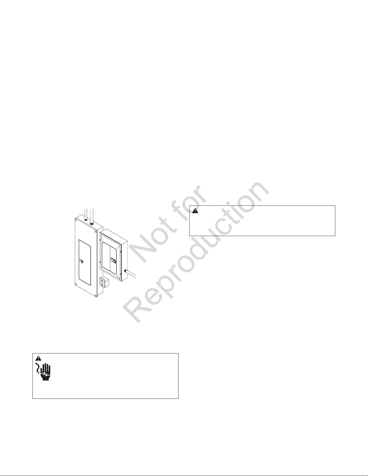
Equipment Description
The transfer switch is designed to transfer the selected
loads found in normal residential installations to generator
power in the event of a utility power failure. The load is
connected either to utility power (normal) or home standby
power (generator). The transfer switch monitors utility and
generator voltages and will automatically connect to the
appropriate source of power.
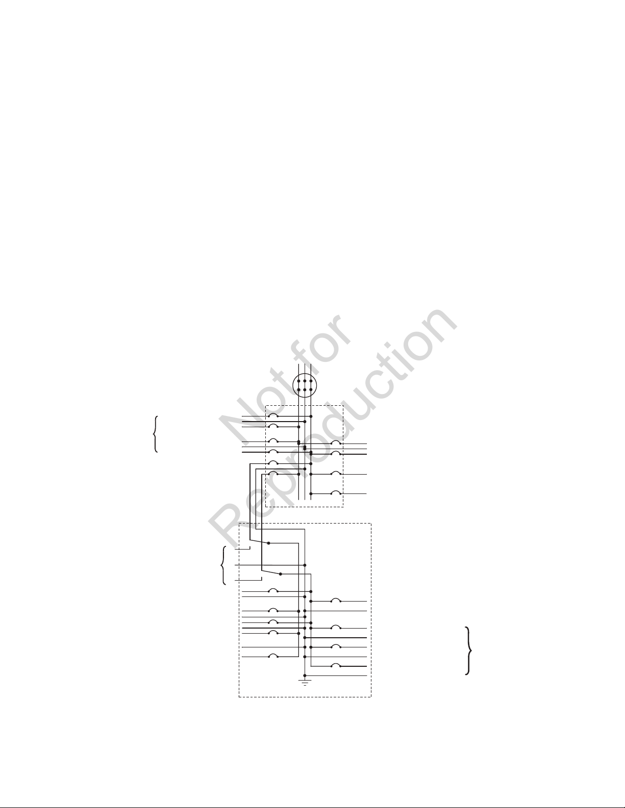
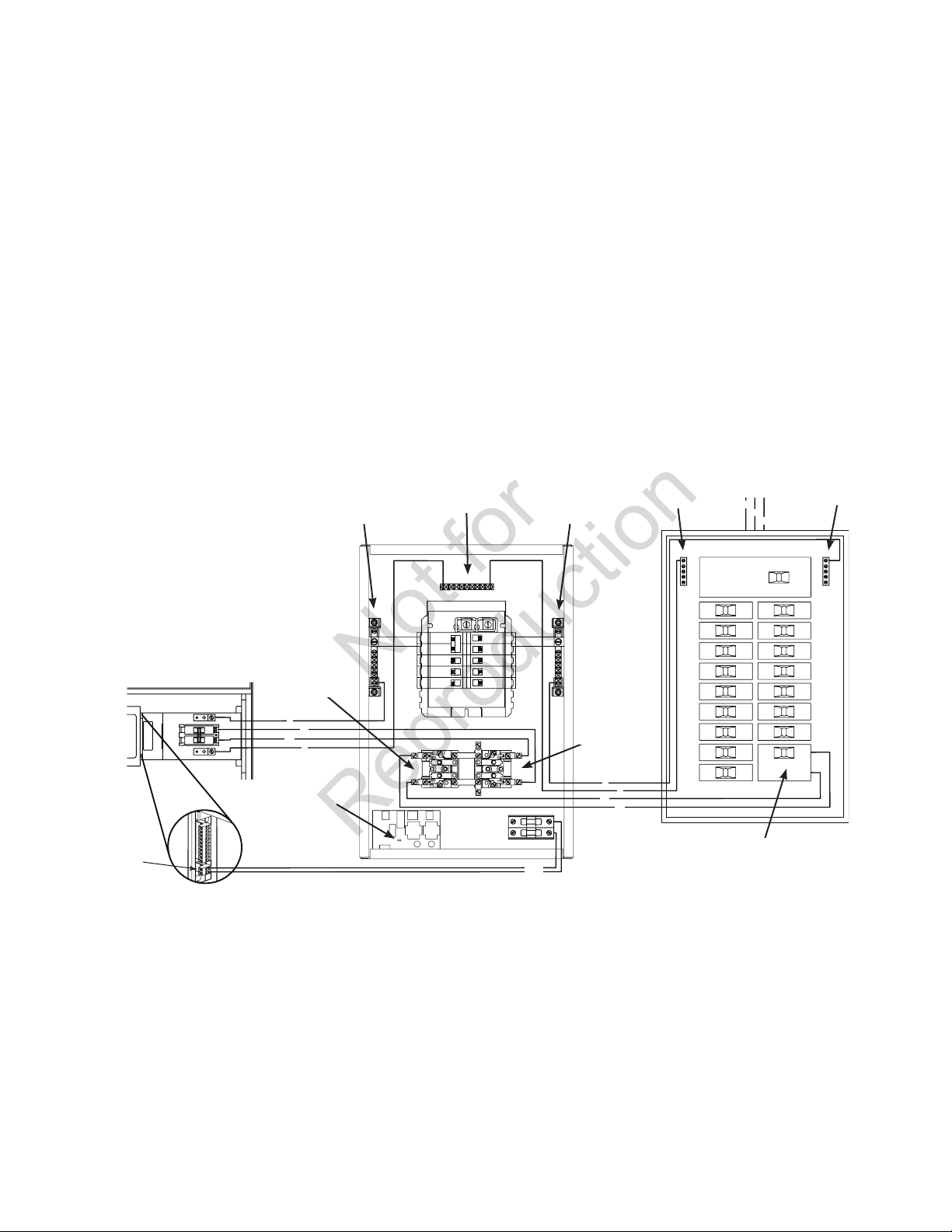
Major components of the transfer switch are 2 pole
contactor switches, control circuit board, fused utility
terminals and interconnecting wiring.
The transfer switch is coil-operated from utility or generator
inputs and contains suitable electrical interlock switches to
eliminate the possibility of connecting the utility service to
the generator output.
The control board has active circuits sensing utility and
generator voltages. It creates a signal for the generator start-
up, switch transfer, retransfer when utility is restored and
generator cool down periods.
Not for
Reproduction

6 BRIGGSandSTRATTON.COM
Delivery Inspection
After opening the carton, carefully inspect the transfer
switch components for any damage that may have occurred
during shipment.
If loss or damage is noted at time of delivery, have the
person(s) making delivery note all damage on the freight bill
and affix his signature under the consignor’s memo of loss
or damage. If loss or damage is noted after delivery, contact
the carrier for claim procedures. Missing or damaged parts
are not warranted.
Shipment contents
• Automatictransferswitch(1)
• Installationandoperator’smanual(1)
To be supplied by installer:
• Connectingwireandconduit
• Variousspecialtytools/equipment
Essential Circuit Isolation
Essential electrical loads are loads that will be powered by
the home generator. Essential loads are grouped together
and wired into the transfer switch.
TO THE INSTALLER: Consult with home generator owner(s)
to discuss their selection of “Essential Circuits”.
Ensure that the total of the selected load circuits fed by this
transfer switch are within the generator’s rated capacity.
The following requirements apply to this type of
isolation system:
• Theautomatictransferswitchisinstalledafterthemain
distribution panel.
• Theautomatictransferswitchhasaloadratingof
50 Amps. This is the maximum load rating of the total
essential load.
• Allwiringmustconformtonational,stateand
local codes.
The illustration below depicts the system installation and
assumestheutilityissupplying120/240Volt,single-phase
electrical service.
To Utility Power
Watt-Hourrmeter
Main Distribution Panel
ToAirConditioner(240V)
ToOtherCircuits(120V)
To Range
To Water Heater
240V
To generator
120VToMicrowave
120VToBathroom
240VToWellPump
120VToSumpPump
Neutral
120V
To Furnace Blower
To Lights
To Refrigerator
120VToFreezer
Automatic Transfer Switch
(in normal position)
Not for
Reproduction

7
Mounting Guidelines
The model 01917 automatic transfer switch is enclosed in a
NEMA Type 1 enclosure suitable for indoor use only. Model
01918 is identical circuitry enclosed in a NEMA Type 3R
enclosure suitable for indoor/outdoor use.
Guidelines for mounting the switch enclosure include:
• Model01918automatictransferswitchmustbe
installed with minimum NEMA 3R hardware for
conduit connections.
• Installtheswitchonafirm,sturdysupportingstructure.
• Topreventswitchcontactdistortion,leveland
plumb the enclosure. This can be done by placing
washers between the switch enclosure and the
mounting surface.
• Neverinstalltheswitchwhereanycorrosivesubstance
might drip onto the enclosure.
• Protecttheswitchatalltimesagainstexcessive
moisture, dust, dirt, lint, construction grit and
corrosive vapors.
A typical indoor transfer switch installation is depicted
below. Discuss layout suggestions/changes with the owner
before beginning the system installation process.
Power Wiring Interconnections
All wiring must be the proper size, properly supported
and protected by conduit. All wiring should be done per
applicable federal, state and local codes, standards and
regulations. Obey wire type and torque specifications printed
on terminal blocks and neutral/ground connectors.
Complete the following connections between the transfer
switch, main distribution panel, utility power and generator.
Useinstaller-supplied300VACorgreaterwirethatcomplies
with Table 310.16 in the National Electric Code. Apply the
necessary correction factors and wire size calculations.
1. Set generator’s system switch to OFF position.
2. Set generator’s circuit breaker to OFF (open) position
and remove 15 Amp fuse from system control panel.
3. Turn off utility power to the standby generator and
transfer switch.
4. Usinginstallersupplied300VACorgreaterwire,
connect utility power supply leads from a 50 Amp
two pole breaker installed in main distribution
panel to transfer switch terminals marked “UTILITY
CONNECTION”. Ensure breaker is turned OFF.
5. Usinginstallersupplied300VACorgreaterwire,
connect main distribution panel ground to transfer
switch “GND” bus.
6. Usinginstallersupplied300VACorgreaterwire,
connect main distribution panel neutral to transfer
switch “NEUTRAL” terminal.
7. Usinginstallersupplied300VACorgreaterwire,
connect power supply leads from generator
control panel to transfer switch terminals labeled
“GENERATOR CONNECTION”.
8. Usinginstallersupplied300VACorgreaterwire,
connect Neutral from generator control panel to
transfer switch “NEUTRAL” terminal.
9. Usinginstallersupplied300VACorgreaterwire,
connect “GND” from generator control panel to transfer
switch “GND” terminal.
Automatic
transfer
switch
Main
distribution
panel
WARNING Low voltage wire cannot be installed in
same conduit as power voltage wiring.
Failure to follow above warning could cause personal• injury, damage and/or malfunction of equipment.
NOTICE Improper installation can cause damage to the
circuit boards and shorten their life. Installing circuit
boards in live circuits will damage the board and is not
covered by warranty. ALWAYS disconnect ALL sources of
power prior to servicing.
Remove all power prior to installing this equipment.• Failure to do so could cause internal damage to the board
when making electrical connections.
Turn generator to• OFF position.
Turn off utility power to the standby generator and• transfer switch.
WARNING Battery posts, terminals and related
accessories contain lead and lead compounds, chemicals
known to the State of California to cause cancer and
reproductive harm. Wash hands after handling.
Not for
Reproduction

8 BRIGGSandSTRATTON.COM
10. Connecttransferswitch“UTILITY240VAC”terminals
togenerator’s“240VAC”terminalsusinginstaller
supplied300VACorgreatercopperwire,minimum
#14 AWG conductors via two-pole connector supplied
with generator.
11 If generator is installed in an area regularly subjected
to temperatures below 40°F (4°C), select a 50 second
warm up time by removing jumper installed on JP2 on
transfer switch control board.
12. Connect essential circuit loads to appropriate circuit
breakers in transfer switch.
13. Tighten all wire connections/fasteners to torque values
specified on label inside enclosure.
• Torquegeneratorconnectorplugscrewsto7in-lb
(7.9 Newton meter).
The illustration below shows a typical completed installation.
Your actual installation will vary.
System Test
With the generator system switch in AUTO, turn the
50 Amp circuit breaker feeding the transfer switch to the
OFF position. After a few minutes the generator will start
and the transfer switch will transfer essential loads to
generator power.
To return to utility power, turn the 50 Amp circuit breaker
feeding the transfer switch ON.
240
VAC
240VAC
G
E1
E2
N
G
L1
L2
N
L1
L2
N
Automatic Transfer Switch
Two Pole
Breaker
Utility
Connection
JP2
Generator
Connection
To Watt-
Hourmeter
Neutral
Bus
Neutral
Bus
Neutral
Bus
Ground
Bus
Ground
Bus
Main Distribution PanelB&S Generator
Not for
Reproduction

9
Operation
To select automatic transfer operation, do the following:
1. Set 50 Amp circuit breaker feeding the transfer switch
to “ON” position.
2. Install 15 Amp fuse in generator’s control panel.
3. Set generator’s circuit breaker to “ON” position.
4. Set generator’s system switch to “AUTO” position.
The system will now be in automatic operation mode.
NEMA 3R Enclosure Door
To open door, press the spring-load door lock to the right
and pull down on the door.
To close and latch door, push door closed against enclosure.
While in this position, push door upwards. This will cause
spring-load door lock to engage and latch door in place.
Enclosure door MUST be closed and latched at all times
except when system is being serviced.
Testing the Automatic Transfer Switch
Turn the 50 Amp utility disconnect circuit breaker in the
main distribution panel to the “OFF” position. The automatic
sequence will follow. To go back to utility power, turn the
50 Amp utility disconnect circuit breaker “ON”.
Automatic Sequence
Utility Fail
Utility voltage sensor senses when utility voltage is below
70% of nominal. Engine start sequence is initiated after
6 second time delay.
Engine Warm-Up
Time delay to allow for engine warm-up before transfer. Use
jumper on control board to select delay of 20 seconds or
50 seconds.
Transfer
Transfer from utility to generator supply occurs after
generator voltage is above set levels. Minimum engine run
time is 5 minutes after transfer.
Utility Pickup
Voltagepickuplevelis80percentofnominalvoltage.
Retransfer
Retransfer from generator to utility power is approximately
10 seconds after utility voltage supply is above pickup level
and minimum run time is completed.
Engine Cool Down
Engine will run for 60 seconds after retransfer.
Maintenance
The transfer switch is designed to be maintenance free under
normal usage. However, inspection and maintenance checks
should be made on a regular basis. Maintenance will consist
mainly of keeping the transfer switch clean.
Visualinspectionsshouldbedoneatleastonceamonth.
Access to transfer switch must not be obstructed. Keep
3 feet (92 cm) clearance around transfer switch. Check
for an accumulation of dirt, moisture and/or corrosion
on and around the enclosure, loose parts/hardware,
cracks and/or discoloration to insulation, and damaged or
discolored components.
Exercise the transfer switch at least once every three months
as described in Testing the Automatic Transfer Switch
unless a power outage occurs and home generator has gone
through an automatic sequence. Allow generator to run for at
least 30 minutes.
Contact a licensed electrical professional to inspect and clean
the inside of the enclosure and other components of your
home generator system at least once a year.
When Calling for Assistance
You must have the Model Number and Serial Number from
the unit ID label at hand if it is necessary to contact a local
service center regarding service or repair of this unit. Obtain
this information from the unit ID label located on or inside
the enclosure.
To contact Briggs & Stratton call (800) 743 4115, between
8:00 AM and 5:00 PM CT.
Installation Inspection
Before placing the system into service, inspect the entire
installation carefully.
Complete the ”Installation Checklist” as you make the
inspection. Ensure all items have been filled-in and all
signatures have been obtained. Instruct the owner to mail
the white copy to the address shown on the checklist.
Not for
Reproduction

10 BRIGGSandSTRATTON.COM
Troubleshooting
Problem Cause Correction
Automatic transfer switch does not
transfer to generator 1. Generator breaker open.
2. Generator voltage not acceptable. 1. Reset generator circuit breaker.
2. Refer to generator manual.
Automatic transfer switch does not
transfer to utility
1. Main distribution panel breaker open.
2. Utility voltage not acceptable. 1. Reset main distribution panel breaker.
2. Wait for utility voltage to return
to normal.
Generator is still running after switch
transfers to utility power Engine cool down period. Engine should stop after 1 minute.
Generator is still running after utility
power is restored
1. Minimum engine run time has
not elapsed.
2. Fuse(s) in transfer switch is defective.
1. Wait five minutes for transfer switch
to retransfer to utility power.
2. Check fuse(s) and replace
if necessary
Not for
Reproduction

11
Schematic Diagram
Not for
Reproduction

12 BRIGGSandSTRATTON.COM
Wiring Diagram
Not for
Reproduction

13
Warranty
ABOUT YOUR WARRANTY
We welcome warranty repair and apologize to you for being inconvenienced. Any Authorized Service Dealer may perform warranty repairs. Most warranty
repairs are handled routinely, but sometimes requests for warranty service may not be appropriate. For example, warranty service would not apply if
equipment damage occurred because of misuse, lack of routine maintenance, shipping, handling, warehousing or improper installation. Similarly, the
warranty is void if the manufacturing date or the serial number on the equipment has been removed or the equipment has been altered or modified. During
the warranty period, the Authorized Service Dealer, at its option, will repair or replace any part that, upon examination, is found to be defective under normal
use and service. This warranty will not cover the following repairs and equipment:
• Normal Wear: Outdoor Power Equipment, like all mechanical devices, needs periodic parts and service to perform well. This warranty does not cover
repair when normal use has exhausted the life of a part or the equipment.
• Installation and Maintenance: This warranty does not apply to equipment or parts that have been subjected to improper or unauthorized
installation or alteration and modification, misuse, negligence, accident, overloading, improper maintenance, repair or storage so as, in our judgment,
to adversely affect its performance and reliability. This warranty also does not cover normal maintenance such as adjustments, cleaning and
fuse replacement.
• Other Exclusions: This warranty excludes wear items or damage or malfunctions resulting from accidents, abuse, modifications, alterations, or
improper servicing. Accessory parts are excluded from the product warranty. This warranty excludes failures due to acts of God and other force
majeure events beyond the manufacturers control. Also excluded is used, reconditioned, and demonstration equipment. 198180E, Rev. C, 12/31/2006
BRIGGS & STRATTON POWER PRODUCTS GROUP, LLC
MILWAUKEE, WI, USA
BRIGGS & STRATTON POWER PRODUCTS GROUP, LLC TRANSFER SWITCH OWNER WARRANTY POLICY
LIMITED WARRANTY
Briggs & Stratton Power Products Group, LLC will repair or replace, free of charge, any part(s) of the equipment that is defective in material or
workmanship or both. Transportation charges on product submitted for repair or replacement under this warranty must be borne by purchaser. This
warranty is effective for the time periods and subject to the conditions stated below. For warranty service, find the nearest Authorized Service Dealer in
our dealer locator map at BRIGGSandSTRATTON.COM.
THERE IS NO OTHER EXPRESS WARRANTY. IMPLIED WARRANTIES, INCLUDING THOSE OF MERCHANTABILITY AND FITNESS FOR A PARTICULAR
PURPOSE, ARE LIMITED TO ONE YEAR FROM PURCHASE, OR TO THE EXTENT PERMITTED BY LAW. ANY AND ALL IMPLIED WARRANTIES ARE
EXCLUDED. LIABILITY FOR INCIDENTAL OR CONSEQUENTIAL DAMAGES ARE EXCLUDED TO THE EXTENT EXCLUSION IS PERMITTED BY LAW. Some
states or countries do not allow limitations on how long an implied warranty lasts, and some states or countries do not allow the exclusion or limitation
of incidental or consequential damages, so the above limitation and exclusion may not apply to you. This warranty gives you specific legal rights and you
may also have other rights which vary from state to state or country to country.
Effective November 1, 2005 replaces all undated Warranties and all Warranties dated before November 1, 2005
The warranty period begins on the date of purchase by the first retail consumer or commercial end user, and continues for the period of time stated in the
table above. “Consumer use” means personal residential household use by a retail consumer. “Commercial use” means all other uses, including use for
commercial, income producing or rental purposes. Once equipment has experienced commercial use, it shall thereafter be considered as commercial use for
purposes of this warranty. Equipment used for prime power in place of utility are not applicable to this warranty.
NOWARRANTYREGISTRATIONISNECESSARYTOOBTAINWARRANTYONBRIGGS&STRATTONPRODUCTS.SAVEYOURPROOFOFPURCHASE
RECEIPT.IFYOUDONOTPROVIDEPROOFOFTHEINITIALPURCHASEDATEATTHETIMEWARRANTYSERVICEISREQUESTED,THEMANUFACTURING
DATE OF THE PRODUCT WILL BE USED TO DETERMINE THE WARRANTY PERIOD.
3 years
None
Consumer Use
Commercial Use
WARRANTY PERIOD
Not for
Reproduction

14 BRIGGSandSTRATTON.COM
Product Specifications
Model 01917
Enclosure.................................................................. NEMA 1
Rated Maximum Load Current*
(at 25°C/77°F) ........................................................50 Amps
RatedACVoltage.................................................... 250Volts
Poles.................................................................................... 2
Frequency ................................................................50/60 Hz
Fault Current Rating......... 5,000 RMS Symmetrical Amperes
Normal Operating Range .... -20°F (-28.8°C) to 104°F (40°C)
Weight ............................................................27 lbs. (12 kg)
* This transfer switch is certified in accordance with UL (Underwriters
Laboratories) 1008 (transfer switch equipment). Short circuit rating is
limited to the lowest capacity of any device installed.
Model 01918
Enclosure................................................................NEMA 3R
Rated Maximum Load Current*
(at 25°C/77°F) ........................................................ 50 Amps
RatedACVoltage.................................................... 250Volts
Poles.................................................................................... 2
Frequency ................................................................50/60 Hz
Fault Current Rating......... 5,000 RMS Symmetrical Amperes
Normal Operating Range .... -20°F (-28.8°C) to 104°F (40°C)
Weight ............................................................30 lbs (14 kg).
Automatic Transfer Switch
Not for
Reproduction

Home Generator Systems
Manual de instalación y del operario
50 Amperios
Interruptor de
transferencia automática
Not for
Reproduction

2 BRIGGSandSTRATTON.COM
Gracias por comprar este conectador automático de Briggs & Stratton® Power Products. Este producto está diseñado para
utilizarse con generadores de reserva domésticos específicos y puede no funcionar con generadores producidos por otros
fabricantes. Recurra a un electricista profesional cualificado para determinar la aplicabilidad de este equipo en generadores
fabricados por terceros. Si se utiliza y mantiene de acuerdo con las instrucciones de este manual, su sistema le proporcionará
muchos años de funcionamiento fiable.
Este manual contiene información de seguridad para que usted conozca los peligros y riesgos propios de este sistema y
cómo evitarlos. Se ha realizado el máximo esfuerzo para que la instalación resulte segura, sencilla y económica. Debido a que
cada instalación es única, es imposible conocer y recomendar todos los procedimientos y métodos posibles para efectuarla.
No conocemos todos los riesgos y/o resultados posibles de cada método o procedimiento existente. Es importante que lea
y comprenda perfectamente estas instrucciones antes de intentar instalar o utilizar este equipo. Guarde estas instrucciones
para futuras consultas.
Este el conectador requiere instalación profesional antes de utilizarse. Consulte las instrucciones sobre los procedimientos
de instalación en la sección Instalación del presente manual. Los conectador sólo deben ser instalados por electricistas con
licencia. Las instalaciones deben cumplir estrictamente la totalidad de los códigos, estándares y regulaciones federales,
estatales y locales vigentes. El instalador debe seguir las instrucciones detalladamente.
Ubicación
Nunca debe ir demasiado lejos para encontrar el soporte y servicio de Briggs & Stratton para su sistema. Consulte las
Páginas Amarillas. Existen múltiples distribuidores de servicio autorizados que ofrecen un servicio de calidad. También puede
comunicarse con el Servicio técnico por teléfono al (800) 743 4115 de 8:00 a. m. a 5:00 p. m. Hora del Centro, hora del
centro de los EE. UU; o haga clic en Buscar un distribuidor en BRIGGSandSTRATTON.COM para que aparezca una lista de
distribuidores autorizados.
Para futuras consultas
Llene la siguiente información y conserve su factura para facilitar la identificación de la unidad en caso de que surjan
problemas relacionados con la compra en el futuro.
Conectador automático
Número de modelo
Revisión
Número de serie
Fecha de compra
Briggs & Stratton Power Products Group, LLC
P.O. Box 702
Milwaukee, WI 53201-0702
Copyright © 2010. Reservados todos los derechos. Queda prohibida la reproducción
o transmisión total o parcial de este material, sin el permiso previo y por escrito de
Briggs & Stratton Power Products Group, LLC.
Not for
Reproduction

3
Tabla de contenido
Instrucciones importantes de seguridad ................4
Instalación ....................................5
Orientación al propietario.......................................5
Responsabilidades del distribuidor / técnico instalador................5
Pautas de montaje ............................................7
Interconexión de los cables de alimentación ........................7
Prueba del sistema............................................8
Funcionamiento.................................9
Mantenimiento ................................ 10
Resolución de problemas ......................... 10
Garantía . . . . . . . . . . . . . . . . . . . . . . . . . . . . . . . . . . . . . 11
Especificaciones del producto ...................... 12
Not for
Reproduction

4 BRIGGSandSTRATTON.COM
Guarde estas instrucciones
Instrucciones importantes
de seguridad
GUARDE ESTAS INSTRUCCIONES - Este manual contiene
instrucciones importantes que se deben seguir durante la
instalación y el mantenimiento del equipo.
Símbolos sobre la seguridad y significados
El símbolo de alerta de seguridad indica un posible
riesgo para su integridad física. Se utiliza una palabra de
señalización(PELIGRO,ADVERTENCIAoATENCIÓN)junto
con el símbolo de alerta para designar un grado o nivel
de gravedad de riesgo. Se puede utilizar un símbolo de
seguridad para representar el tipo de riesgo. La palabra de
señalizaciónAVISOseutilizaparahacerreferenciaauna
práctica no relacionada con una lesión física.
PELIGRO indica un riesgo que, de no evitarse, provocará
la muerte o lesiones de gravedad.
ADVERTENCIA indica un riesgo que, de no evitarse,
podría provocar la muerte o lesiones de gravedad.
ATENCIÓN indica un riesgo que, de no evitarse, podría
provocar lesiones leves o moderadas.
AVISO hace referencia a una práctica no relacionada con una
lesión física.
El fabricante no puede prever toda circunstancia que conlleve
un riesgo potencial. Por tanto, las advertencias de este
manual, así como las etiquetas y calcomanías adheridas a
la unidad, no incluyen todos los riesgos posibles. Si utiliza
un procedimiento, método de trabajo o técnica de uso no
recomendado específicamente por el fabricante, deberá
asegurarse de que es seguro tanto para usted como para
otras personas. También deberá asegurarse de que el
procedimiento, método de trabajo o técnica de uso que elija
no hace que el equipo sea inseguro.
Descarga eléctrica Lea el manual
AVISO La instalación de este equipo debe cumplir
estrictamente la totalidad de los códigos, estándares y
regulaciones vigentes, por lo que sólo debe ser llevada a
cabo por un electricista cualificado.
ADVERTENCIA Determinados componentes en
este producto y los accesorios relacionados contienen
sustancias químicas declaradas cancerígenas, causantes
de malformaciones, y otros defectos congénitos por el
Estado de California. Lávese las manos después de
manipular estos elementos.
ADVERTENCIA Los cables de baja tensión no se
pueden instalar en el mismo conducto que los
cables de suministro de energía.
Si no se respeta esta indicación pueden producirse• lesiones, daños y/o fallos de funcionamiento del equipo.
ADVERTENCIA Una conexión a tierra defectuosa del
equipo puede provocar la electrocución.
No toque los cables pelados.•
No utilice el equipo con cables desgastados,• deshilachados o deteriorados de cualquier otra forma.
No manipule los cables eléctricos si se encuentra en• una zona húmeda, está descalzo o tiene las manos o los
pies mojados.
Si tiene que trabajar junto a una unidad en• funcionamiento, manténgase en una superficie aislada y
seca para reducir el riesgo de descarga eléctrica.
No permita que personas no cualificadas o niños utilicen• o reparen el equipo.
En caso de accidente provocado por una descarga• eléctrica, desconecte inmediatamente todos los
suministros de energía eléctrica y póngase en contacto
con las autoridades locales. Evite el contacto directo con
la víctima.
ADVERTENCIA El equipo contiene alta tensión que
puede provocar lesiones o la muerte.
A pesar de la seguridad del diseño del sistema, si éste se• utiliza con imprudencia, ignorando su mantenimiento o
sin las debidas precauciones, se pueden producir lesiones
o incluso la muerte.
AVISO Un tratamiento inadecuado del equipo puede
estropearlo y acortar su vida útil.
Utilice el equipo sólo para los usos previstos.•
En caso de dudas sobre su uso, diríjase al distribuidor o a• Briggs & Stratton Power Products.
No exponga el equipo a un exceso de humedad, polvo,• suciedad o vapores corrosivos.
Manténgase alerta en todo momento cuando utilice este• equipo. Nunca lo utilice ni manipule en condiciones de
fatiga física o mental.
Si se calientan excesivamente los dispositivos conectados,• apáguelos y abra sus interruptores o quite sus fusibles.
Not for
Reproduction

5
Instalación
Realmente valoramos que nos haya elegido. Por este
motivo, se ha realizado un esfuerzo importante para que
la instalación resulte segura, sencilla y económica. Debido
a que cada instalación es única, es imposible conocer y
recomendar todos los procedimientos y métodos posibles
para efectuarla. Tampoco conocemos todos los riesgos y/o
resultados posibles de cada método o procedimiento.
Por tanto, la instalación del sistema sólo puede ser
llevada a cabo por un electricista con licencia vigente.
Las instalaciones deben cumplir estrictamente la
totalidad de los códigos, estándares de la industria y
regulaciones vigentes.
Su equipo se suministra con este “Manual de instalación
y del operario” combinado. Se trata de un documento
importante que el propietario debe conservar después de
haber terminado la instalación.
Se ha realizado el máximo esfuerzo para reunir en este
manual la información más precisa y actualizada. No
obstante, el fabricante se reserva el derecho de modificar,
alterar o mejorar de cualquier otra forma el sistema en
cualquier momento y sin previo aviso.
Responsabilidades del propietario
Para tomar decisiones bien fundadas y comunicarse
eficazmente con el técnico instalador, lea y comprenda la
sección Orientación al propietario antes de contratar o
iniciar la instalación del equipo.
Para solicitar la instalación, póngase en contacto con la
tienda en la que adquirió el equipo, con su distribuidor o con
la compañía eléctrica.
La garantía del equipo quedará ANULADA a menos
que electricistas profesionales con licencia instalen
el sistema.
Orientación al propietario
Las ilustraciones incluidas corresponden a circunstancias
habituales y tienen por objeto familiarizarle con las opciones
de instalación del sistema.
La normativa local, la apariencia y las distancias son los
aspectos que deberán tenerse en cuenta al negociar la
instalación con un profesional. Al aumentar la distancia
desde el servicio eléctrico, se deberá prever una
compensación en cables y otros materiales necesarios
para cumplir la normativa local vigente y evitar caídas de
tensión eléctrica.
Estos factores tendrán un efecto directo en el precio total de
la instalación del equipo.
El instalador deberá comprobar la normativa local Y obtener
los permisos correspondientes antes de instalar el sistema.
• Leaysigalasinstruccionesqueseindicanen
este manual.
• Sigaunplanregulardecuidadoyusodelequipo,como
se indica en este manual.
Responsabilidades del distribuidor /
técnico instalador
• Leayrespetelasnormasdeseguridad.
• Leaysigalasinstruccionesqueseindicanen
este manual.
• Esposiblequeelinstaladortengaqueproporcionar
contactores nominales adecuados con base en las
cargas que van a controlarse.
• Consultelanormativavigenteencasodedudassobre
la instalación.
• Asegúresedequelascargasseleccionadasno
sobrecargan el generador.
Si necesita más información sobre el conectador, llame al
(800) 743-743-4115, de 08:00 a 17:00 CT.
Descripción del equipo
El conectador está diseñado para transferir las cargas
seleccionadas de una instalación residencial normal
al suministro del generador en caso de un fallo en el
suministro de alimentación de la red pública. La carga
se conecta al suministro de servicio general (normal)
o al suministro doméstico de reserva (generador). El
conectador monitoriza las tensiones de la red pública y del
generador y conecta automáticamente la carga a la fuente de
alimentación apropiada.
Los componentes principales del conectador son los
interruptores de contacto bipolares, la tarjeta de circuito
impreso de control, los terminales con fusibles de tensión de
la red pública y el cableado de interconexión.
El conectador es accionado por una bobina alimentada
desde entradas de la red pública o del generador y tiene
interruptores de enclavamiento eléctricos, adecuados para
eliminar la posibilidad de conectar la red pública a la salida
del generador. Sus valores nominales son suficientes para
conectar la potencia del generador a la residencia.
La tarjeta de circuito impreso del módulo de control tiene
circuitos activos que detectan las tensiones de la red pública
y del generador. Genera una señal para el arranque del
generador, conectador, retransferencia cuando se restablece
la tensión en la red pública y períodos de enfriamiento
del generador.
Not for
Reproduction

6 BRIGGSandSTRATTON.COM
Inspección en el momento de la entrega
Después de abrir la caja de cartón, con cuidado inspeccione
el contenido para detectar cualquier daño que pudiera haber
ocurrido durante el envío.
Si detecta faltas o daños en el momento de la entrega,
solicite a la persona que realiza la entrega que anote
todos los daños en Ia nota de entrega y que la firme bajo
el área de pérdidas y daños del remitente. Si se detectan
faltas o daños después de la entrega, póngase en contacto
con el transportista para solicitar información sobre el
procedimiento de reclamación. La garantía no cubre las
partes faltantes o dañadas.
Contenido del paquete
• Conmutadordetransferenciadeenergíaautomático(1)
• Manualdeinstalaciónyoperario(1)
No incluye:
• Cableyconductodeconexión.
• Herramientas/equiposespecialesdiversos
Aislamiento de los circuitos fundamentales
Las cargas eléctricas fundamentales son aquellas que
serán alimentadas mediante el sistema de generador. Las
cargas fundamentales se agrupan y se conectan dentro del
compartimiento del conmutador de transferencia automático.
AL INSTALADOR: Consulte con el propietario del
sistema de generador para analizar la “Selección de los
circuitos fundamentales”.
Asegúrese de que el total de los circuitos de carga
seleccionados para ser alimentados por este conmutador de
transferencia se encuentre dentro de la capacidad nominal
del generador.
Los siguientes requisitos se aplican a este tipo de sistema
de aislamiento:
• Elconmutadordetransferenciaautomáticoseinstala
después de instalar el panel de distribución principal.
• Elconmutadordetransferenciaautomáticotieneun
valor nominal de carga de 50 Amperios. Este es el valor
nominal máximo para las cargas fundamentals totales.
• Todaslasconexionesdecableadodebencumplircon
lo establecido en el nacional, todos los códigos locales
y estatales.
La ilustración muestra el sistema de generador y supone
que la compañía proveedora de electricidad entrega
120/240Voltios,concorrientemonofásica.
A la energía de la compañía proveedora de electricidad
Vatímetro
Panel de distribución principal
Alacondicionadordeaire(240V)
Aotroscircuitos(120V)
A la cocina
Al calentador de agua
240V
A la generador
120Valhornodemicroondas
120Valcuartodebaño
240VAlabombadepozo
120VAlabombadesumidero
Neutro
120V
Al soplador de caldera
A las luces
Al refrigerador
120Valfreezer
Conmutador de transferencia
automático (en posición normal)
Not for
Reproduction
Table of contents
Languages:
Other GE Switch manuals

GE
GE MultiLink ML600 User manual

GE
GE 98209-1 User manual

GE
GE GE-DSG-8 DSGH-5 User manual

GE
GE GuardSwitch 300 Series User manual

GE
GE SBM User manual

GE
GE GE-DSH-82 Assembly instructions

GE
GE 45853GE User manual

GE
GE "ExecutiveSeries"USB2.0 HO97863 User manual

GE
GE Digital Energy STS-230-25-2-RM User manual

GE
GE DS-242-POE Assembly instructions