GE ABB ReliaGear LV SG User manual

INSTALLATION, OPERATIONS AND MAINTENANCE MANUAL
ReliaGear® LV SG
Low voltage switchgear

These instructions convey information that pertains to
ReliaGear® LV SG low voltage switchgear.
These instructions do not purport to cover all details or
variations in equipment nor to provide for every possible
contingency to be met in connection with installation,
operation or maintenance. Should further information be
desired or should particular problems arise which are not
covered sufficiently for the Purchaser's purposes, the
matter should be referred to your ABB sales representative.
These instructions are intended for use by qualified
personnel only.

2
TABLE OF CONTENTS
Table of contents
03 Warranty and general information
04– 06 Introduction
07– 13 Receiving, handling and storage
14 – 27 Switchgear description
28 – 43 Equipment installation
44 – 47 Installing and removing circuit
48 – 49 Testing and inspection
51– 53 Cooling fan control module
54– 58 Operating the switchgear
59 Energizing the switchgear
60– 64 Maintaining the switchgear
65–74 Appendices

3RELIAGEAR®LV SG LOW VOLTAGE SWITCHGEAR
Warranty and general
information
Hazard classifications
The following important highlighted information
appears throughout this document to warn of
potential hazards or to call attention to information
that clarifies a procedure.
Carefully read all instructions and become familiar
with the devices before trying to install, operate,
service or maintain this equipment.
Danger: Indicates a hazardous situation which, if
not avoided, will result in death or serious injury.
Warning: Indicates a hazardous situation
that, if not avoided, could result in death
or serious injury.
Caution: Indicates that if the hazard is not avoided
could result in minor or moderate injury.
Notice: Is used to notify of practices not related to
personal injury.
Trademarks
SACE Emax 2®
SACE Emax 2 Ekip®
ReliaGear® LV SG
All third-party trademarks are the property of their
respective owners.
Warranty
This document is based on information available at
the time of publication. While efforts have been
made to ensure accuracy, the information
contained herein does not cover all details or
variations in hardware and software, nor does it
provide for every possible contingency in
connection with installation, operation, and
maintenance. Features may be described herein
that are not present in all hardware and software
systems.
ABB assumes no obligation of notice to holders of
this document with respect to changes
subsequently made. ABB makes no representation
or warranty, expressed, implied, or statutory, with
respect to, and assumes no responsibility for the
accuracy, completeness, sufficiency, or usefulness
of the information contained herein.
No warrantees of merchantability or fitness for
purpose shall apply. Contact your local sales office
if further information is required concerning any
aspect of ReliaGear LV SG switchgear and SACE
Emax 2 breaker operation or maintenance.
DANGER
WARNING
CAUTION
NOTICE
DANGER
WARNING
CAUTION
NOTICE
DANGER
WARNING
CAUTION
NOTICE
DANGER
WARNING
CAUTION
NOTICE

4
INSTALLATION, OPERATIONS AND MAINTENANCE MANUAL
General information
This manual contains procedures for receiving,
handling, storage, equipment installation,
operation, and maintenance and service of
ReliaGear LV SG low voltage switchgear.
Notice: The personnel responsible for installing,
operating, and servicing this equipment should
be thoroughly familiar with the contents of
this manual.
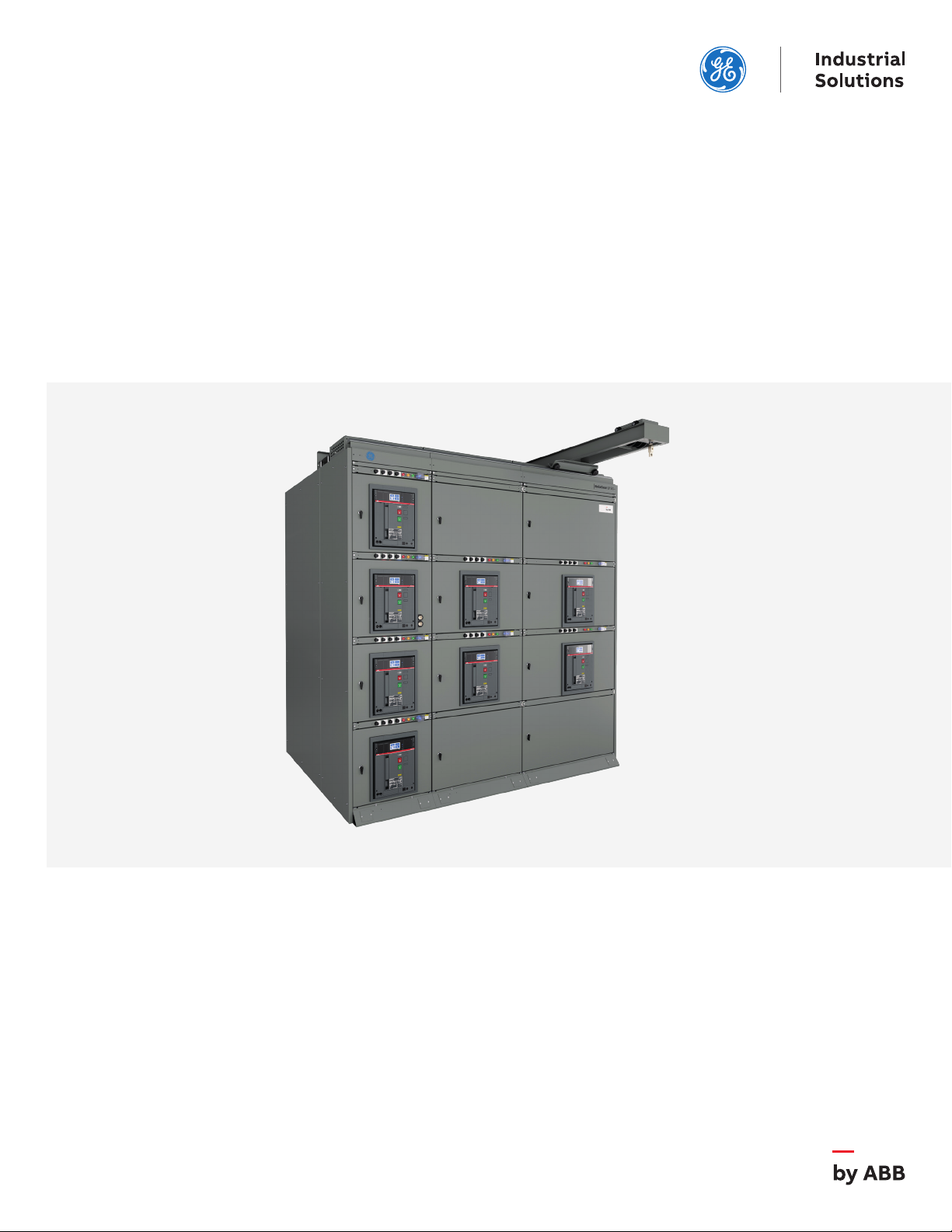
Before any installation work is performed,
thoroughly read and understand the material in this
instruction manual and the drawings furnished
with the equipment. The As-built documentation
shipped with the equipment includes the Summary,
Front View, Elementary Diagram, and Connection
Diagram. This material is located in a forward
compartment tagged "INSTRUCTIONS IN THIS
COMPARTMENT." The documentation provides all
of the information necessary for installation of the
switchgear. When requesting information from
ABB, include the complete data appearing on the
equipment nameplate, requisition number,
summary number, and elementary diagram
number. The nameplate is located in
the lower left, front corner of the lineup.
When requesting information concerning any
specific item furnished with the switchgear, refer
to that item by description, part number, its
location within this manual, and any applicable
drawing number. Any material external to the
equipment, which may be required to meet local
codes (such as mats, screens, railings, etc.), is not
furnished by ABB.
If there are any questions or requirements not
covered in this manual or in the accompanying
drawings, please contact your ABB
sales representative.
Introduction
Instruction book arrangement
Information and procedures in this instruction
book are divided as follows:
Introduction: gives a brief account of the
equipment's function and provides for general
information, and applicable data for the equipment
and its components.
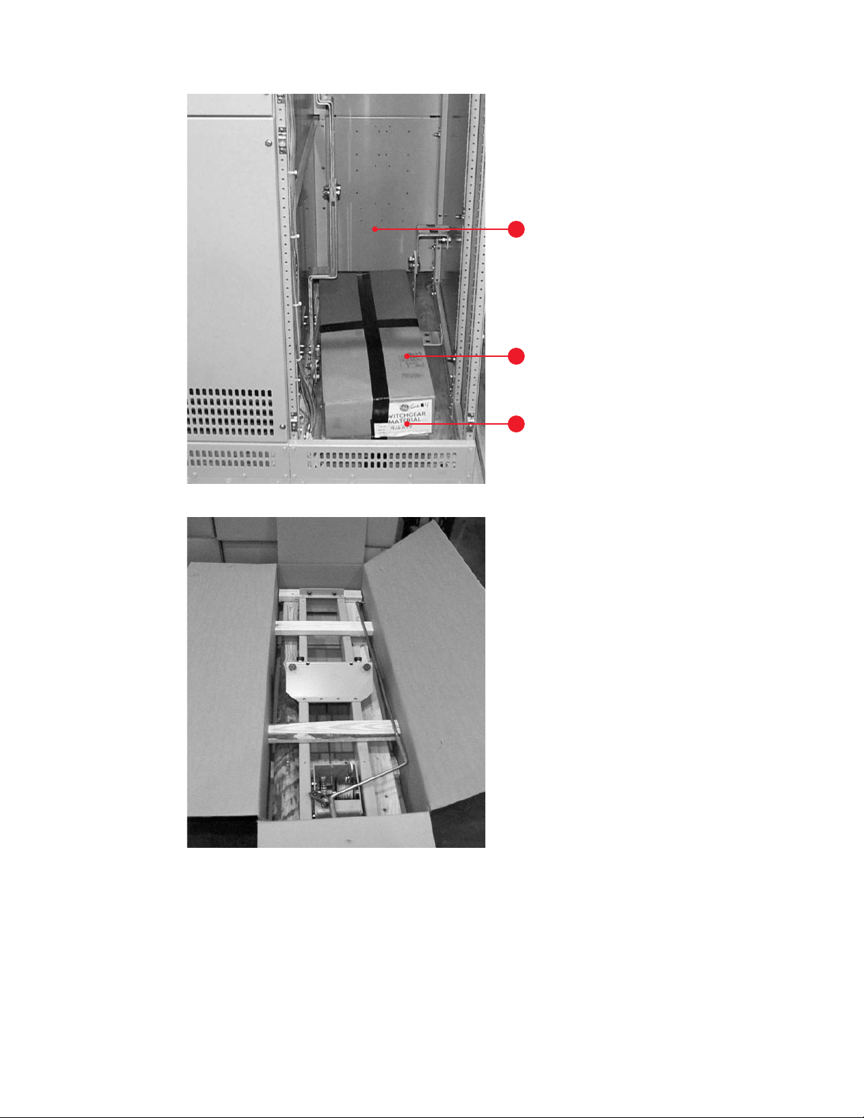
Receiving, handling and storage: describes
procedures required for receiving and handling the
equipment and how to prepare it for
short-or long-term storage.
Switchgear description: describes the ReliaGear LV
SG low voltage switchgear and its various
components. Included are the section enclosure,
breaker compartment, circuit breakers, instrument
panels and instrument compartments, bus bar
arrangement, incoming cable and busway, ground
and neutral bus, outdoor equipment, and auxiliary
section. This section also explains how the
electrical and mechanical components perform
their assigned functions.
Equipment installation: provides the information
needed prior to installation, site location and
foundation requirements, and how to anchor
the equipment properly and safely. It also covers
installation of peripheral equipment and includes
information on electrical connections and
mechanical construction.
Installing and removing circuit breakers: gives
a step-by-step procedure for lifting the breaker
from the floor, installing it on draw-out rails, and
moving it into the connected position.
A further procedure is given to withdraw a breaker,
remove it from the draw-out rails, and lower it to
the floor. Also included is a description of the
rejection system provided to avoid the inadvertent
use of an incorrect breaker
in a breaker compartment.
DANGER
WARNING
CAUTION
NOTICE

5RELIAGEAR®LV SG LOW VOLTAGE SWITCHGEAR
Testing and Inspection: reviews items which
should be tested or inspected prior to energizing
and operating the switchgear.
Cooling fan control module: describes the
components, setup, test and maintenance
procedures for the optional cooling fan
compartment.
Operating the switchgear: covers how to
operate the breakers, and contains information
concerning draw-out provisions, doors, and various
accessories.
Energizing the switchgear: outlines the steps
to be taken before and during the electrical
energization of the equipment.
Maintaining the switchgear: provides instructions
for all preventive maintenance, servicing, and
lubrication information for the switchgear
equipment. Included is service and maintenance
data for the circuit breakers, instrument
compartments, instruments, bus
bar joints, and cable and busway connections. This
section also includes paint refinishing
requirements.
Appendices A, B, C and D contain information
concerning screw and bolt torque values,
circuit breaker rejection features, circuit
breaker information and spare parts.
Related publications
Addenda to this instruction book are the available
service and maintenance publications supplied
separately for circuit breakers, relays
and other devices not described in this
instruction book.
—
01
ReliaGear LV SG
low voltage
switchgear
In addition to instruction books, the following As-
built documentation will be supplied as required
for each order of ReliaGear LV SG switchgear
equipment:
1. General arrangement drawings, including front
view and floor plan.
2. Elementary and connection drawings (or wiring
routing tables) which indicate and identify test
and connection points including terminal blocks,
device studs, switch contact developments, and
remote connections.
3. Summary of switchgear equipment which is
a list of all the components furnished with the
switchgear, including the breakers, identified
by catalog number.
These are all the documents necessary to install,
operate, and maintain the equipment. One
complete set of drawings and this instruction
book is shipped with the equipment. An electronic
copy of this documentation package is also sent to
the customer after shipment.
—
01

6
INSTALLATION, OPERATIONS AND MAINTENANCE MANUAL
Receiving
Equipment packages
Every package leaving the factory is plainly marked
with the case number and customer's order
number. If the equipment has been split for
shipment, the section numbers of the equipment
enclosed in each shipping package are identified.
Notice: To avoid the loss of any parts when
unpacking, the contents of each container should
be carefully checked against the packing list before
discarding the packing material.
The contents of each shipping package are listed
on the Master Packing List. In addition, this list
includes the number of the shipping crate in which
miscellaneous parts needed to install and operate
the equipment (such as hardware, contact
lubricant, touch-up paint, breaker closing devices,
etc.) are located. Normally, such devices are packed
in a cardboard carton and the carton secured in an
empty switchgear compartment. See Figure 02. If
such items are packed in a switchgear section
instead of a separate crate, the list will indicate
the appropriate section number in which they are
stored. Large items (such as breaker lifting devices
and dollies used with indoor equipment) will always
be shipped in separate crates or cartons.
See Figure 03.
Inspecting for damage
All equipment leaving the factory is carefully
inspected and packed by personnel experienced
in the proper handling and packing of electrical
equipment. Upon receipt of any equipment,
immediately perform a visual inspection to
ascertain if any damage has been sustained in
shipping or if there are any loose parts. Circuit
breakers may be shipped separately in individual
containers with the breaker in the open position.
Circuit breakers should be unpacked and visually
inspected for damage or loose parts as soon as
possible after they have been received.
Be sure to inspect all devices mounted or packed
inside compartments of each section to see if any
have been dislodged or damaged.
Filing a claim
If any damage is evident, or indication of rough
handling is visible, file a claim for damage at once
with the transportation company and notify your
ABB sales representative immediately. Information
on damaged parts, part number, case number,
requisition number, etc., should accompany
the claim.
Receiving, handling and storage
DANGER
WARNING
CAUTION
NOTICE

7RELIAGEAR®LV SG LOW VOLTAGE SWITCHGEAR
Spare compartment
Carton containing loose material
Shipping label
1
2
3
—
02
Packaging of loose
material for shipment
—
03
Carton containing
breaker lifting device

8
INSTALLATION, OPERATIONS AND MAINTENANCE MANUAL
Handling
Notice: It is preferable to leave the
shipping skids in place under the
switchgear until it reaches its final
location. The equipment should be
installed in its final location prior to
installing the circuit breakers.
Indoor enclosure lifting
The indoor switchgear sections are best handled by
lifting with a crane as shown in Fig. 04. Removable
lifting plates are provided, as standard equipment,
on the top of each switchgear section. To preserve
the external appearance of the equipment, it is
suggested that the lifting plates be left in place
except where adjacent equipment must be bolted
together, i.e. shipping splits, etc.
Utilize four equal length cables and an overhead
crane, each with a minimum load rating of twice the
weight of the switchgear. Estimated weights for
shipping splits appear on the Front View drawings.
Example: Switchgear section weight = 5,000
pounds. The crane and the four lift cables must
have a minimum load lifting capacity of
10,000 pounds.
Warning: The angle between the
cables and the top of the equipment
must be at least 45 degrees. If this is
not possible because of lack of
headspace, spreader bars must be
used. Also, lift cables with greater
load capability may be necessary,
depending upon the angle between
the cables and the crane hook.
Connect a cable from the crane to the four lifting
plates located on the top-front and rear of the
switchgear (Figure 04).
—
04
—
04
Recommended method of
lifting indoor enclosure
—
05
Warning label is located
on each corner by
the lifting plate
—
05
DANGER
WARNING
CAUTION
NOTICE
DANGER
WARNING
CAUTION
NOTICE

9RELIAGEAR®LV SG LOW VOLTAGE SWITCHGEAR
—
06
Location of lifting plates
of outdoor enclosure
—
07
Warning label is
located on each side
by the lifting plate
—
07
1. Lifting plate
2. Lifting plate mounting bolts
3. Shipping skid
1
2
3
Take up the slack in the lifting device very carefully
and manually stabilize the switchgear to prevent it
from rotating.
Warning: Do not stand under switchgear while it is
being moved. Serious injury may occur if the cables
or lifting device fail.
Caution: Gently lower the switchgear section onto
the level site location. If the switchgear is roughly
handled or jarred, it is possible to damage or
misalign internal components.
Outdoor enclosure lifting
Methods of lifting outdoor switchgear sections are
much the same as for indoor equipment except the
lifting plates are provided at the base of the
structure. See Figure 06.
If lifting outdoor switchgear sections, side support
timbers must be placed along the sides to prevent
any damage that could be caused by the lifting
cables.
In addition, spreader bars must be inserted
between each lift cable, both front and rear.
Spreader bar locations must be on the sides and
above the switchgear equipment as shown in
Fig. 06. Proceed to lift and place the outdoor
switchgear utilizing all the precautions and
requirements that apply to lifting the indoor
switchgear. The lifting plates, Figure 05, should
be removed after the equipment is permanently
anchored so passageways at the ends of the
equipment will not be obstructed.
Rollers
If crane facilities are not available, the equipment
may be moved into position by means of
construction rollers placed under the shipping
skids. The switchgear may be raised enough for the
placement of rollers by means of a fork lift or jack.
There should never be less than four rollers under
the equipment unless the line-up is less than five
feet long. Use one roller for each 18 inches of
equipment length.
DANGER
WARNING
CAUTION
NOTICE
DANGER
WARNING
CAUTION
NOTICE

10
INSTALLATION, OPERATIONS AND MAINTENANCE MANUAL
Forklifts
When using a forklift to raise the line-up to position
rollers underneath, proceed as follows:
1. Expand forklift tines to their maximum
(widest) extension.
2. Carefully insert tines of forklift below one side of
the switchgear line-up at the approximate center
of the panel as shown in Figure 09.
Notice: Do not attempt to lift or
move the equipment with a forklift
positioned in the front or rear of the
equipment.
3. Raise equipment and position one roller under
the skids close to the raised end of the line-up.
4. Carefully lower the gear until it rests on the roller
as shown in Figure 10.
5. Repeat the lifting process at the other end and
place the appropriate number of rollers under
the skids spacing them evenly across the width
of the line-up.
Spreaders and
timber not
furnished with
equipment
Front Timber
—
09
—
08
—
10
—
Front view
—
08
Recommended method
of lifting outdoor
enclosure (using
cable spreaders)
—
09
Placing forklift tines
under equipment
shipping skid
—
10
Placement of rollers
under shipping skid
—
Side view
DANGER
WARNING
CAUTION
NOTICE

11 RELIAGEAR®LV SG LOW VOLTAGE SWITCHGEAR
Lifting plates must
be removed where
sections are joined
—
Front view
—
Side view
Roller
—
11
Method of rolling
equipment into place
—
11
Notice: If shipping skids are removed prior to final
placement of equipment, rollers may only be used
to move the equipment in a direction parallel to
the front.
6. Carefully lower the gear until it rests on the
rollers (Figure 10).
7. While carefully pushing the switchgear to its final
site position, the rollers that are freed from the
rear of the switchgear are then repositioned at
the forward end. This procedure should be
continued until the switchgear is in its final
location (Figure 11).
8. When the switchgear is in its final position,
remove all lug bolts holding the shipping skids
to the switchgear line-up.
9. Insert the tines of the forklift at one end of
the line-up, raise slightly, and remove the
loose rollers.
10. Lower the end of the gear carefully
to the floor.
11. Raise the other end of the line-up slightly and
remove the remaining roller at that end.
DANGER
WARNING
CAUTION
NOTICE

12
INSTALLATION, OPERATIONS AND MAINTENANCE MANUAL
—
12
—
13
—
12
Recommended
method of jacking
outdoor equipment
—
Side view
Wood beam
Jacks
Jacks may be used in place of forklifts to raise and
lower switchgear.
1. Place a jack under the front and rear corners
of one end of the line-up. Figure 12 and 13
illustrate the use of jacks with outdoor
equipment.
Caution: Do not place jacks in any other location
other than the front and rear corners of the
switchgear. Doing so may result in serious damage
to the switchgear equipment.
2. Raise the switchgear evenly and just enough to
position a roller beneath the equipment. Gently
lower the switchgear onto the rollers. Repeat the
procedure at the opposite end of the switchgear,
raising the gear far enough to place the
appropriate number of rollers under the skids,
spacing them evenly across the width
of the line-up. Gently lower the gear onto
the rollers.
—
13
Recommended
method of jacking
outdoor enclosure
—
Partial front or rear
view of jacking
—
Partial side view
of jacking
—
Front view
Jacking timber
not furnished with
switchgear
Cable
Rear or front
Jack here
3. While carefully pushing the switchgear to its final
site position, the rollers that are freed from the
rear of the switchgear are then repositioned at
the forward end. This procedure should be
continued until the switchgear is in its final
location.
4. When the switchgear is in its final position,
remove all lag bolts holding the shipping skids to
the switchgear line-up.
5. Place one jack at each corner, front and rear, of
the switchgear. Carefully raise the line-up evenly
and remove the rollers and the shipping skids.
Evenly lower the line-up to the floor and remove
the jacks.
DANGER
WARNING
CAUTION
NOTICE

13 RELIAGEAR®LV SG LOW VOLTAGE SWITCHGEAR
Storage
Switchgear
If it is necessary to store the switchgear equipment
for any length of time, the following precautions
should be taken to prevent corrosion or
deterioration.
1. Remove protective covering. Check thoroughly
for damage.
2. Store in a clean, dry, rodent-free location
with moderate temperature and provide
protective coverings to prevent dirt, water,
or other foreign substances from entering
the switchgear.
Caution: Remove all cartons, containers and any
other miscellaneous packaging and packing
material from inside the switchgear sections
before energizing any internal heaters. To prevent
fire, remove any plastic or polyethylene shrouding
from the switchgear sections before energizing any
internal heaters.
3. If dampness or condensation may be
encountered in the storage location, heaters
must be placed inside the switchgear sections to
prevent moisture damage. Approximately 250
watts of heat in each section is required. On
outdoor switchgear equipment, this may be
accomplished by making a temporary power
supply connection to the heaters already
installed in the equipment.
Caution: If the space heaters are to
be temporarily energized from
external source, it is important to
remove the fuses on the secondary
side of the control power
transformer. This precaution is to
prevent a feedback of higher voltage
to other portions of the equipment
through the CPT primary.
Circuit breakers
If circuit breakers are not to be placed into service
at once, remove them from their shipping cartons
and thoroughly inspect them for damage. If the
breakers are in satisfactory condition, replace the
breakers in their shipping cartons for storage. Do
not remove the circuit breaker shipping members
at this time.
Store the circuit breakers in a clean, dry location
in an upright position. They must be properly
supported to prevent bending of the stud or
damage to any of the breaker parts. Do not remove
any protective grease until the circuit breakers are
ready to be installed. A plastic or canvas-type cover
should be provided to reduce the possibility of
damage to the breakers due to dust and water.
For more details, please see 1SDH001330R1002.
DANGER
WARNING
CAUTION
NOTICE
DANGER
WARNING
CAUTION
NOTICE

14
INSTALLATION, OPERATIONS AND MAINTENANCE MANUAL
General
This section contains a description of the
ABB low voltage switchgear. It also describes the
functions of the electrical and mechanical systems.
Figure 14 is a side view of a typical section showing
compartmentation.
Summary description
ABB low voltage switchgear is a freestanding
assembly of metal-enclosed sections containing
low voltage power circuit breakers, bus bars, cable
termination provisions, auxiliary power circuit
protective devices, controls, and instrumentation.
It may also be an integral part of a load center unit
substation, either single-ended or double-ended.
Switchgear description
Intersectional
control wiring
trough
Breaker or
instrument
compartment
A
B
C
D
Breaker
compartment
Breaker
compartment
Breaker
compartment
Neutral bus
Vertical riser
bus bars
Cable termination
area
Breaker
compartment run
back and cable
termination
Main bus bars
Instrument
panel or
entelliguard
messneger
Vertical
control wire
gutter
Compartment
doors
Compartment
doors
Cable
compartment
doors
Ground bus
Enclosed trough
for external
control circuit
wiring
—
14
Side-view section of
low voltage switchgear
—
14

15 RELIAGEAR®LV SG LOW VOLTAGE SWITCHGEAR
All of the primary circuit switching and protective
devices, secondary control and metering devices,
control fuses and instrument transformers,
are mounted in the enclosure. The breaker
compartments include draw-out rails, stationary
breaker contacts, interlocks and necessary control
and indicating devices.
The breakers are provided with self-aligning
primary and secondary disconnecting contacts,
breaker locking mechanism, and integral trip unit.
The individual sections, compartments, and
devices are described in the following paragraphs.
Figure 15 is an outline of a typical single-ended load
center unit substation illustrating the
nomenclature used for all equipment.
A
A A
B
B B
C C
D D D
A
B
Primary section Transformer ReliaGear LV SG section
Load center unit substation
Shipping
package
Shipping
package
Transition
section
Shipping
package
Switch unit Breaker sections
—
15
Outline of a typical load
center unit substation
—
15

16
INSTALLATION, OPERATIONS AND MAINTENANCE MANUAL
Compartment area
The front enclosure of each section is divided into
individual compartments. These compartments
house either a low voltage power circuit breaker
or are used to mount instruments, control
components and other ancillary devices.
Instrument panel
A standard instrument panel, Figure 16, is located
above each breaker compartment eliminating
cross-hinge wiring. When required, optional
devices may be included and mounted on the
front face of the panel such as breaker control
circuit fuses, pilot lights, and a RELT switch.
Fuses for the charge, close, and trip circuits of the
electrically operated SACE Emax 2 breakers are
mounted on the panel. Routine wiring inspections
and fuse checks or fuse replacements can be
performed with the breaker compartment door in
the closed position so that operators are protected
from the energized primary circuits.
1. Control circuit fuses
2. Pilot lights
3. RELT switch and indication
1
2
3
—
16
ReliaGear LV SG
instrument panel
—
16
Instrument/auxiliary compartment
An instrument/auxiliary compartment, Figure 17,
is available as a standard feature. Relays, fuse
cutouts, and similar devices may be installed
in the instrument compartment or in
adjacent compartments.
—
17
Instrument/auxiliary
compartment
—
17

17 RELIAGEAR®LV SG LOW VOLTAGE SWITCHGEAR
Breaker compartment
Closed-door draw-out circuit breaker
compartments are standard construction with all
switchgear equipment. The circuit breaker
compartment doors remain closed and latched
while the breaker is racked out from the
CONNECTED position, through TEST, to
the DISCONNECTED position.
Breaker compartment doors do not have any
ventilation slots, thus protecting operators from
gases which may be vented by the breaker during
circuit interruption. Additionally, the breaker
compartment, Figure 19 and 20, is enclosed by
grounded steel barriers on the top, sides, bottom,
and front. In the back, a flame-retardant, track
resistant, glass-filled polyester base minimizes
the possibility of fault communication between
compartments or to the bus.
1. Breaker position indicator
2. “Push to operate” racking mechanism button
(shown engaged)
3. Racking handle
4. Racking handle storage
1. Secondary disconnects
2. Position switch location (not shown)
3. Primary disconnect stab tip (typical)
1. Circuit breaker mounted racking mechanism
—
18
—
18
Emax 2 circuit breaker
compartment
—
20
—
21
—
20
Circuit breaker
compartment for Emax
2 circuit breakers
—
21
Emax 2 circuit breaker's
racking mechanism.
—
19
Circuit breaker
compartment for Emax
2 circuit breakers
1
2
3
4
2
3
1
1
1. Cradle side barrier
2. Draw-out rails
3. Cradle pan
—
19
1
3
2

18
INSTALLATION, OPERATIONS AND MAINTENANCE MANUAL
The cradle draw-out rails, item 2 in Figure 19,
engage the racking mechanism, item 1 in Figure 20,
on the sides of the breaker. The breaker is pulled
into the compartment and locked in its final
connected position through the operation of the
racking handle.
The breaker should always be OPEN when it is
moved into or out of the CONNECTED position.
As a safeguard, a draw-out interlock will prevent
operation of the racking mechanism unless the
breaker is OPEN.
All SACE Emax 2 circuit breakers are provided
with a mechanical rejection feature. See section
5 of this instruction book for additional details.
Each circuit breaker compartment has four
positions as described in the Table 1.
Movement of the breaker between the
CONNECTED, TEST, and DISCONNECTED positions
is performed by the use of a racking handle, see
Figure 22, which engages the racking mechanism
mounted on the circuit breaker. An optional
remote racking device is also available.
Movement to the WITHDRAWN position is manually
performed after opening the compartment door.
These positions are illustrated and described more
fully in Section 5 of this instruction book.
Warning: The door should NOT be
opened when the circuit breaker is
closed and in the CONNECTED
position. Although the breaker
compartment door may be opened in
any position, it is recommended that
the door only be opened when the
breaker is in the DISCONNECTED or
WITHDRAWN position.
The dedicated front-mounted auxiliary ventilated
compartment is constructed with grounded metal
barriers on all sides resulting in a segregated
compartment thus protecting operators from
gases which may be vented by the breaker during
circuit interruption.
Circuit breaker
position in
the cassette
Primary
disconnects
Secondary
disconnects
Shutter
assembly
Circuit breaker functionality Circuit breaker
door position
Connect Engaged Engaged Opened
• Breaker can be operated mechanically or
electrically.
• Breaker ready for service. Closed
Test Disengaged Engaged Closed
• Breaker can be operated mechanically or
electrically.
• Breaker and control circuits operations can
be tested and verified. Closed
Disconnect Disengaged Disengaged Closed
• Breaker can be operated only mechanically.
• Breaker cannot be removed from the circuit
breaker compartment. Closed
Withdrawn Disengaged Disengaged Closed
• Breaker can be operated
only mechanically.
• Breaker can be removed from
the compartment. Open
1
1. Breaker position indicator
2. Racking handle
—
22
Racking handle for
movement of Emax
2 circuit breakers
—
22
2
DANGER
WARNING
CAUTION
NOTICE

19 RELIAGEAR®LV SG LOW VOLTAGE SWITCHGEAR
Primary disconnect shutters
Primary disconnect shutters, Figure 23, are
equipped as a standard to provide protection
against contact with the energized stationary
primary disconnects when the breaker is removed
from its compartment.
The shutters are constructed from UL approved
flame retardant materials carrying a V0
flammability classification per UL 94.
1. Shutter assembly (open)
2. Primary disconnect stab tip (typical)
The shutters are closed when the breaker is in the
DISCONNECT Position. As the circuit breaker is
racked from the DISCONNECT Position to the TEST
Position the shutters remain fully closed. As the
breaker is racked from the TEST Position to the
CONNECT Position, the shutters open allowing the
breaker to connect to the primary disconnects.
Figure 24 shows the shutter assembly with the
shutter in the open position.
Danger: Hazard of electrical shock or
burn. Turn off power to this
equipment before working inside.
1. Secondary disconnect
2. Shutter assembly (closed with padlock in place)
3. Cradle side barrier
4. Draw-out rails
—
23
Primary disconnect
shutter assembly (shown
in closed position)
—
24
Primary disconnect
shutter assembly (shown
in open position)
—
23
—
24
3
2
1
4
1
2
DANGER
WARNING
CAUTION
NOTICE
Table of contents
Other GE Switch manuals

GE
GE ZB4001 User manual

GE
GE Cync CSWONBLBWF1NN User manual

GE
GE EntelliGuard G Technical Document

GE
GE GE-DSG-8 DSGH-5 User manual

GE
GE GE-DSH-82 Assembly instructions

GE
GE 50 AMP AUTOMATIC TRANSFER SWITCH Setup guide

GE
GE CWLSWDMBWF1 User manual

GE
GE SE-100E User manual

GE
GE GuardSwitch 300 Series User manual

GE
GE Power/Vac VM-4.16 User manual
Popular Switch manuals by other brands

Siemens
Siemens Sivacon S8 operating instructions

DITEC
DITEC COM500ES installation manual

Comtech EF Data
Comtech EF Data CRS-170 Installation and operation manual

H3C
H3C S7500 Series Operation manual

schmersal
schmersal BNS-B20 operating instructions

TRENDnet
TRENDnet TPE-224WS - Web Smart PoE Switch Quick installation guide