PRICING AND AVAILABILITY 800.827.0807
TECH SUPPORT 800.726.8663
RETURN FOR REPAIR 256.963.8722
www.adtran.com
61247004L1-22B
Warranty: ADTRAN will replace or repair this product within the warranty period if it does not meet its published specifications or fails while in service.
Warranty information can be found online at www.adtran.com/warranty.
TROUBLESHOOTING HDSL
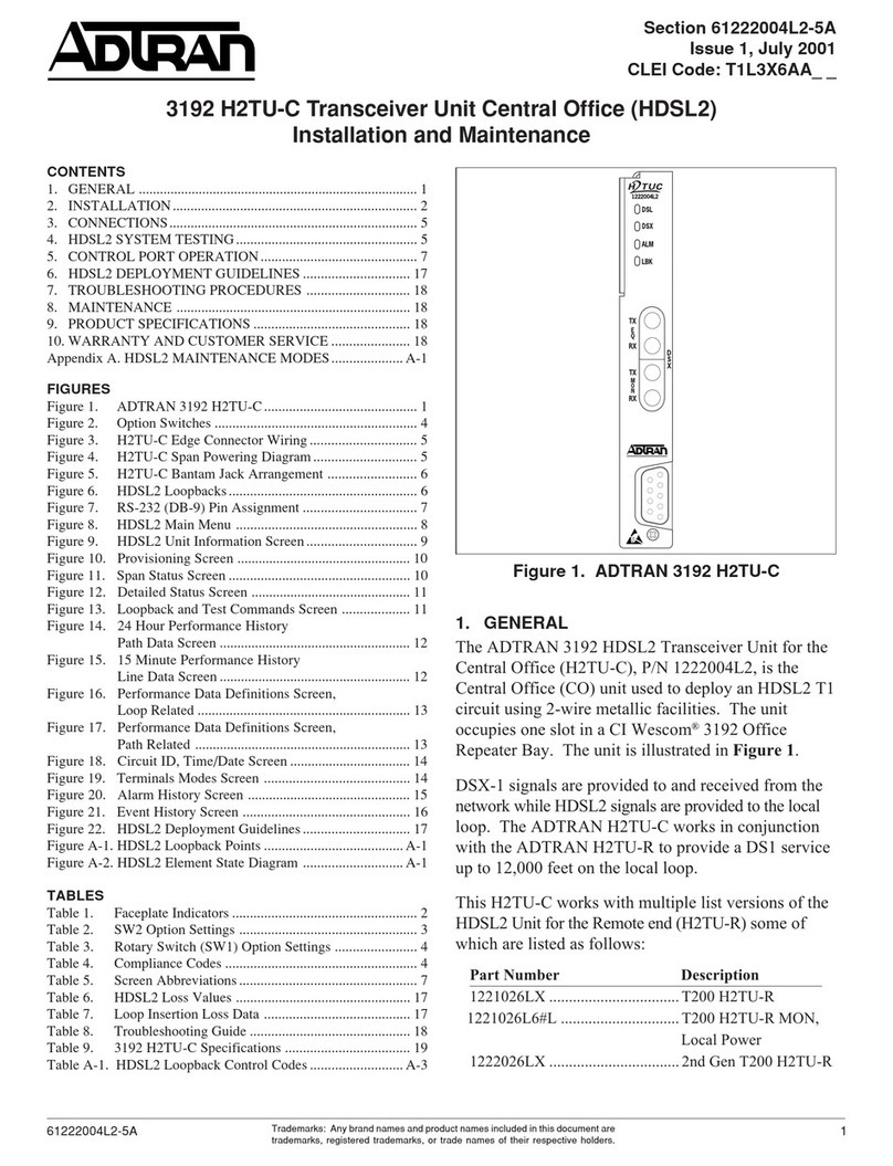
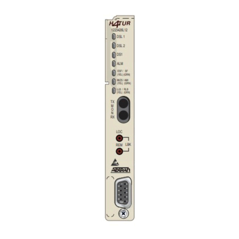
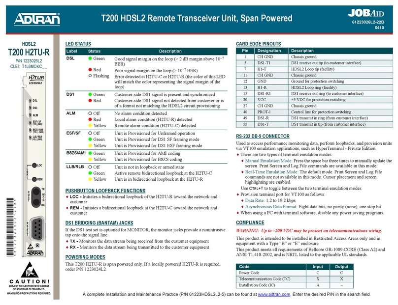
This ADTRAN HDSL unit is equipped with troubleshooting-at-a-glance LEDs (identified on the
reverse side of this document) that provide customers with a simple means of identifying the location
of certain faults.
Additionally, screens available via the craft interface simplify the trouble isolation process. These
screens and their associated benefits are described below.
NOTE: Upon connecting, it may be necessary to press the spacebar three times for the screen to
display properly.
Current System Status Screen
The Current System Status screen is accessed from the Main Menu and provides quick access to status
information for both the HTU-C and the HTU-R. Type “H” once to view current system status for HRE
#1. Type “H” a second time to view the current system status of HRE #2.
Performance History Screen
The Performance History screen is accessed from the Main Menu and provides Performance
information in 15 minute and 24 hour intervals. Type “H” once to view the Performance History screen
for HRE #1. Type “H” a second time to view the Performance History screen for HRE #2.
Troubleshooting Screen
The Troubleshooting screen is accessed from the Main Menu and graphically depicts a HDSL
circuit.The unit reviews red, yellow, and blue alarm conditions in the circuit to automatically predict
where a fault is located. Once a fault location is suspected, the corresponding portion of the circuit on
the screen will be highlighted and a message describing the failure will appear.
PROVISIONING OPTIONS
Setting Options Default
DSX-1 Line Buildout 0-133 feet; 133-266 feet; 266-399 feet; 399-533 feet; 533-655 feet 0-133 feet
DSX-1/DS1 Line Code B8ZS; AMI B8ZS
DSX-1/DS1 Framing Auto; ESF; SF; Unframed; Forced Conversion Auto
NIU Loopback Enabled; Disabled Enabled
New England 1:6 LPBK Disabled; Enabled Disabled
Loopback Timeout None; 60 Min.; 120 Min. 120 Min.
Customer Loss Response AIS; CDI; Loopback AIS
Latching Loopback Mode T1; FTI T1
PRM Mode None; NPRM; SPRM None
DS1 TX Level 0 db; –15 db 0 db
HTUC Shelf Alarm Enabled; Disabled Disabled
Span Power Enabled; Disabled Enabled
DS0 Blocking None blocked; Any of 01-24 blocked or unblocked None blocked
HDSL LOOPBACK CONTROL CODES
Function Code (Binary/Hex) Response
Arm
Source: Network
100000 (1 in 6) Signal sent in-band. HDSL elements in disarmed state
transitions to armed state. Detection of the code results
in an HTUR network loopback if New England
Loopback (NELB) is enabled.
Disarm
Source: Network or Customer
100 (1 in 3) Signal sent in-band. HDSL elements loopdown and
transition to disarmed state.
Activation (HTU-C)
Source: Network
1111 1111 0001 1110/ FF1E Signal sent in-band. HTU-C loops back the T1 data to
the network equipment.
Activation (HTU-C)
Source: Network
1111000 (4 in 7) Signal sent in-band. HTU-C loops back the T1 data to
the network equipment.
Activation (HTU-C)
Source: Customer
1111110 (6 in 7) Signal sent in-band. HTU-C loops back the T1 data to
the customer equipment.
Activation (HTU-C)
Source: Customer
0111 1111 0001 1110/ 3F1E Signal sent in-band. HTU-C loops back the T1 data to
the customer equipment.
Activation (HTU-R)
Source: Network
1111 1111 0000 0010/ FF02 Signal sent in-band. HTU-R loops back the T1 data to
the network equipment.
Activation (HTU-R)
Source: Network
1110000 (3 in 7) Signal sent in-band. HTU-R loops back the T1 data to
the network equipment.
Activation (HTU-R)
Source: Customer
1111100 (5 in 7) Signal sent in-band. HTU-R loops back the T1 data to
the customer equipment.
Activation (HTU-R)
Source: Customer
0111 1111 0000 0010 / 3F02 Signal sent in-band. HTU-R loops back the T1 data to
the customer equipment.
Activation (HTU-R)
Source: Network or Customer
1100 0111 0100 0011/ C742 Signal sent in-band. HTU-R loops back the T1 data to the
source direction. Sends 20 bit errors every 10 seconds.
Activation (HRE-1)
Source: Network or Customer
1100 0111 0100 0001/ C741 Signal sent in-band. HRE-1 loops back the T1 data to the
source direction. Sends 10 bit errors every 20 seconds.
Activation (HRE-2)
Source: Network or Customer
1100 0111 0101 0100/ C754 Signal sent in-band. HRE-2 loops back the T1 data to the
source direction. Sends 200 bit errors every 20 seconds.
Query (All Elements)
Source: Network
1101 0101 1101 0101/ D5D5 Signal sent in-band. Any unit that is in network loopback
injects bit errors into the data looped to the network
equipment. The element closest to the network that is in
loopback injects the errors.
• HTU-C that is in a network loopback injects 231 bit
errors every 20 seconds.
• HTU-R that is in a network loopback injects 20 bit
errors every 10 seconds.
• HRE-1 that is in a network loopback injects 10 bit
errors every 20 seconds.
• HRE-2 that is in a network loopback injects 200 bit
errors every 20 seconds.
Disable Loopback Timeout
Source: Network
1101 0110 1101 0101/ D5D6 Signal sent in-band. Loopback Timeout is disabled as
long as any element is in loopback or armed.
Disable Span Power Source:
Network
0110 0111 0110 0111/ 6767 Signal sent in-band. Span power is disabled until this
pattern is removed.
HDSL
3192 Transceiver Unit for Central Office
