GE Monogram ZV881WSS User manual

GE Monogram®
Installation
Instructions
Professional
Vent Hoods
48" Models
ZV881WSS, ZV891YSS
ZV880WSS, ZV890YSS
36" Models
ZV671WSS, ZV681YSS
ZV670WSS, ZV680YSS
30" Models
ZV370YSS,
ZV371YSS

2
Before you begin—Read these instructions completely and carefully.
IMPORTANT: Save these instructions for local inspector’s use.
IMPORTANT: OBSERVE ALL GOVERNING CODES AND ORDINANCES.
NOTE TO INSTALLER: Be sure to leave these instructions with the Consumer.
NOTE TO CONSUMER: Keep these instructions with your Use and Care Book for
future reference.
This appliance must be properly grounded. See “Electrical Supply”, page 5.
CAUTION
WARNING
If you have questions concerning the installa-
tion of this product, call the GE Answer
Center® Consumer Information Service at
800.626.2000, 24 hours a day, 7 days a week.
If you received a damaged vent hood, you
should contact your dealer.
CAUTION!
Due to the weight and size of these vent hoods
and to reduce the risk of personal injury or
damage to the product, TWO PEOPLE ARE
REQUIRED FOR PROPER INSTALLATION.
WARNING!
To reduce the risk of fire or electric shock, do
not use this range hood with any external
solid-state speed control device. Any such
alteration from original factory wiring could
result in damage to the unit and/or create an
electrical safety hazard.
To reduce the risk of fire and to properly
exhaust air, be sure to duct air outdoors. Do
not vent exhaust air into spaces within walls or
ceilings or into attics, crawl spaces or garages.
WARNING: TO REDUCE THE RISK OF FIRE,
USE ONLY METAL DUCTWORK.
TO REDUCE THE RISK OF FIRE, ELECTRIC
SHOCK OR INJURY TO PERSONS, OB-
SERVE THE FOLLOWING:
A. Use this unit only in the manner intended
by the manufacturer. If you have any ques-
tions, contact the manufacturer.
B. Before servicing or cleaning unit, switch
power off at service panel and lock service
panel to prevent power from being switched
on accidentally.
For general ventilating use only. Do not use
to exhaust hazardous or explosive materials
and vapors.
Installation work and electrical wiring must be
done by qualified person(s). In accordance
with all applicable codes and standards
including fire-rated construction.
Sufficient air is needed for proper combustion
and exhausting of gases through the flue
(chimney) of fuel burning equipment to
prevent back drafting. Follow the heating
equipment manufacturer’s guideline and
safety standards such as those published by the
National Fire Protection Association (NFPA),
and the American Society for Heating, Refrig-
eration and Air Conditioning Engineers
(ASHRAE), and the local code authorities.
Contents Design Information
Models available .................................................................................................................................. 3
Product Dimensions & Clearances .................................................................................................... 4
Advance Planning ............................................................................................................................... 5
Electrical Supply .................................................................................................................................. 5
Installation Preparation
Duct Fittings ....................................................................................................................................... 6
Tools and Materials Required ............................................................................................................ 7
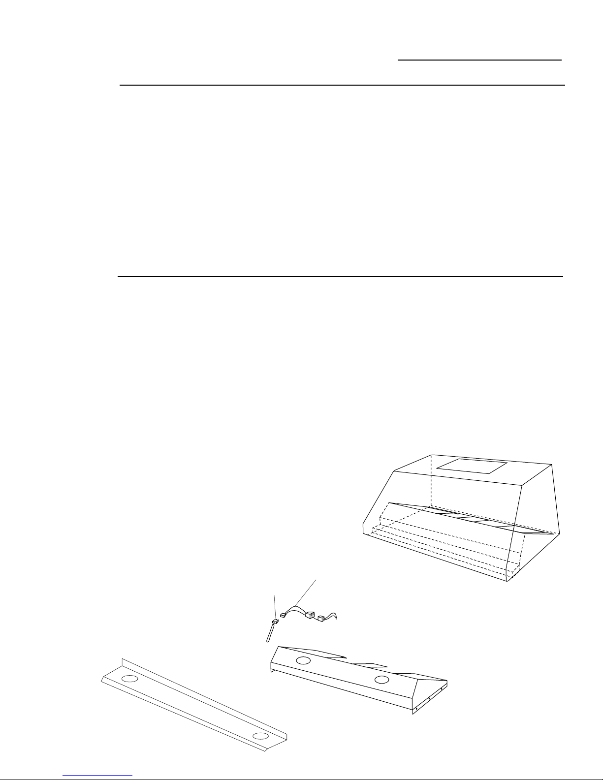
Step 1: Remove the packaging and dis-assemble .............................................................................. 7
Installation
Step 2: Check Installation Hardware ................................................................................................. 8
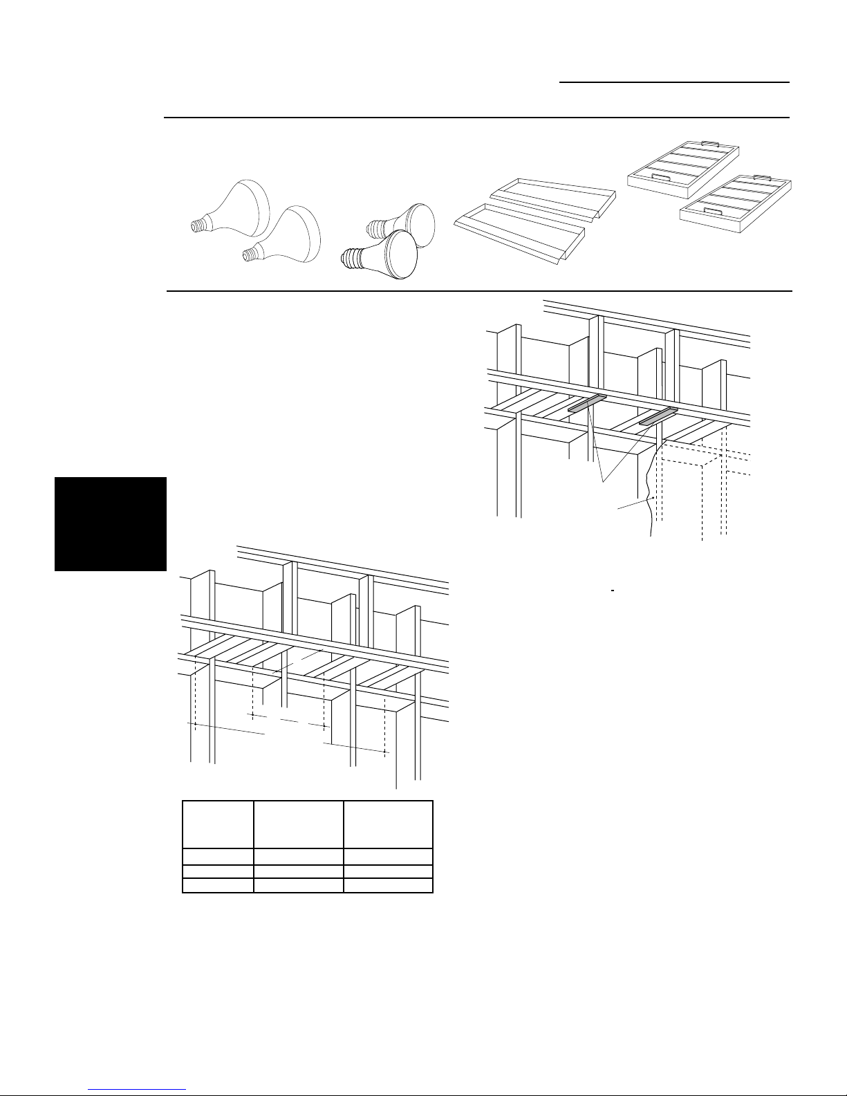
Step 3: Construct Soffit Framing ....................................................................................................... 8
Step 3A: Construct Wall Mount Framing .......................................................................................... 9
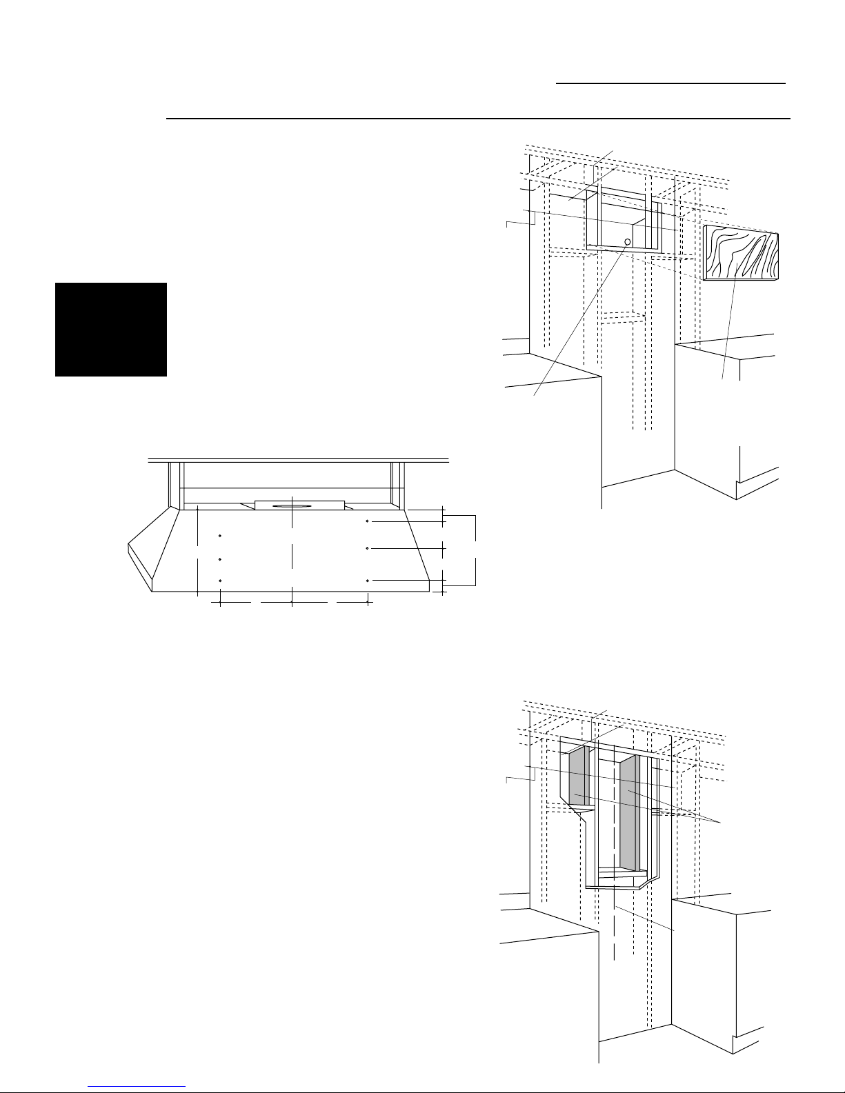
Step 4: Install Hood Below Soffit .....................................................................................................10
Step 4A: Install Hood Onto Wall ..................................................................................................... 11
Step 5: Connect Electrical ................................................................................................................12
Step 6: Connect Ductwork ................................................................................................................12
Step 7: Reassemble Hood.................................................................................................................. 12
Step 8: Install Duct Cover .................................................................................................................13
Step 9: Install Filters ..........................................................................................................................13

3
Design Information
Professional Vent Hoods
Models
Available
These hoods can be installed into a soffit, or
when there is no soffit, they can be installed
directly onto a wall.
48" and 36" wide models are available with
different appearances. Model numbers with
“YSS” have straight sides. Model numbers
ending with “WSS” have sides which taper
inwards from the bottom to the top.
48" Wide Models:
ZV881WSS, ZV880WSS – with tapered sides
ZV891YSS, ZV890YSS – with straight sides
36" Wide Models:
ZV671WSS, ZV670WSS – with tapered sides
ZV681YSS, ZV680YSS – with straight sides
30" Wide Models:
ZV371YSS, ZV370YSS – with straight sides
Before you begin:
Decorative duct covers are available in 6" or
12" heights. The duct covers conceal the
ductwork running from the top of the hood to
the ceiling or soffit. Before you begin, you
should determine the installation height of
the hood and order the correct size duct
cover.
Be sure to order the duct cover which corre-
sponds to your model.
Optional Accessory Duct Covers
Style Hood Model 6" Duct Cover 12" Duct Cover
A-Oval ZV881WSS, ZV880WSS ZX6DC48WSS 6"Hx27-3/8"Wx10-1/4"D ZX12DC48WSS 12"Hx27-3/8"Wx10-1/4"D
A-Oval ZV671WSS, ZV670WSS ZX6DC36WSS 6"Hx22-1/2"Wx9-3/16"D ZX12DC36WSS 12"Hx22-1/2"Wx9-3/16"D
B-Square ZV891YSS, ZV890YSS ZX6DC49YSS 6"Hx47-7/8"Wx12"D ZX12DC49YSS 12"Hx47-7/8"Wx12"D
B-Square ZV681YSS, ZV680YSS ZX6DC38YSS 6"Hx35-7/8"Wx12"D ZX12DC38YSS 12"Hx35-7/8"Wx12"D
B-Square ZV371YSS, ZV370YSS ZX6DC30YSS 6"Hx29-7/8"Wx12"D ZX12DC30YSS 12"Hx29-7/8"Wx12"D
Duct covers for models:
ZV891YSS, ZV890YSS, ZV681YSS, ZV680YSS,
ZV371YSS and ZV370YSS.
Duct covers for models:
ZV881WSS, ZV880WSS, ZV671WSS and
ZV670WSS.
Accessories
(For 48" Wide
Models Only)
Transition duct pieces are available for 48"
wide models. These pieces fit over the outlet
on top of the hood. These transition pieces fit
into a soffit or when there is no soffit, a 12"
duct cover should be used.
Optional 6" or 12"
Duct Cover
Style A-Oval Shape
Optional 6" or 12"
Duct Cover
Style B-Square Shape
ZX48BY, transition to 10" round for horizontal
exhaust.
ZX48AY, transition to 10" round vertical
exhaust.
4-1/2"
10"
18-1/2"
8-3/4"
Duct
Cover
Accessories
8-1/4"
4-3/4" 19-1/4"
C
12"
L
6-5/8"
toC
L

4
Design Information
Professional Vent Hoods
These vent hoods must be installed 30" Min.
and 36" Max. above the cooking surface.
Installation will be easier if the vent hood
is installed before the range or cooktop
installation.
Product
Dimensions
& Clearances
The rating plate is located behind filter
cutouts. To verify your model number, remove
filters.
18"
35"
25" 47-7/8"
12"
18"
23"
25" 35-7/8"
12"
18"
47-7/8"
25" 47-7/8"
12"
ZV891YSS, ZV890YSS
ZV881WSS, ZV880WSS
ZV681YSS, ZV680YSS ZV671WSS, ZV670WSS
18"
29-7/8"
25" 29-7/8"
12"
ZV371YSS, ZV370YSS
SOFFIT
SOFFIT INSTALLATION
30" MIN.
36" MAX."
WALL MOUNT INSTALLATION
Ceiling
30" MIN.
36" MAX."
18"
35-7/8"
25" 35-7/8"
12"

5
Design Information
Professional Vent Hoods
Advance
Planning
Ductwork planning
•Determine the exact location of the vent hood.
•Plan the route for venting exhaust to the
outdoors.
•Use the shortest and straightest duct route
possible. For satisfactory performance, duct
run should not exceed 100 feet equivalent
length for any duct configurations.
•Refer to “Duct Fittings” chart to compute the
maximum permissable length for duct runs to
the outdoors. See page 6.
•Use metal ductwork. For 48" models,
3-1/4" x 24" or 10" round. For 30" and 36"
models, 7" to 10' round or 3-1/4" x 12" to
3-1/4" x 24".
•Install a wall cap with damper or roof cap at
the exterior opening.
Determine the size of the wall or roof cap for
your model and installation.
•Order the caps and any transitions needed in
advance. See “Duct and Duct Fittings” listed in
your local yellow pages. Be sure to include
equivalent lengths of caps and transitions when
calculating the total duct run. See “Duct
Fittings”, page 6.
48" Wide Model Duct Transitions
•Transition duct pieces are available for 48"
wide models. See illustrations of ZX48BY and
ZX48AY transition pieces on page 3.
Installation Framing for adequate support
These vent hoods are heavy. Adequate struc-
tural support must be provided. Hoods must be
secured to vertical studs or to studs in the
soffit.
•Additional studs may be required for a soffit
or wall mount installation. See Step 3, pages 8
and 9.
•We recommend that the vent hood and/or
duct cover be on site before final framing and
wall finishing. This will also help to accurately
locate the ductwork and electrical service.
•Installation will be much easier if the vent
hood is installed before the range or cooktop
below.
Decorative Duct Covers
Decorative duct covers are available for all
models. The duct covers conceal the ductwork
running from the top of the hood to the
ceiling or soffit. Duct covers are available in
6" or 12" heights.
You should:
•Determine the installation height from the
cooking surface.
– 36" max., 30" min.
•Measure 18" hood height.
•Select 6" or 12" duct cover to meet ceiling or
soffit height.
Electrical
Supply
CAUTION
Warning, for
Personal Safety:
Remove house fuse or open
circuit breaker before beginning
installation.
WARNING
Electrical supply
This vent hood must be supplied with 120V,
60Hz., and connected to an individual,
properly grounded branch circuit, protected
by a 15 or 20 ampere circuit breaker or time
delay fuse.
•Wiring must be 2 wire with ground.
•If the electrical supply does not meet the
above requirements, call a licensed electri-
cian before proceeding.
•Connect the wiring to the house wiring in
accordance with local codes.
House wiring location
•The junction box is located on the top of the
hood. See illustrations, page 10 to determine
exact placement.
•Route house wiring through the ceiling, soffit
or back wall as close to the installation location
as possible.
Grounding Instruction
This hood must be connected to a ground metal,
permanent wiring system, or an equipment-
grounding terminal or lead on the hood.
CAUTION
Warning: The improper connec-
tion of the equipment-grounding
conductor can result in a risk of
electric shock. Check with a
qualified electrician or service
WARNING
representative if you are in doubt whether
the appliance is properly grounded.
Do not use an extension cord or adapter
plug with this appliance. Follow National
electrical codes or prevailing local codes
and ordinances.

6
Installation Preparation
Professional Vent Hoods
Duct
fittings
Total
Equivalent Quantity Equivalent
Duct Piece Dimensions Length* Used Length
Round, 1 ft.
straight (per foot
length)
3-1⁄4" x 12" or 1 ft.
3-1/4" x 24" (per foot
straight length)
90°elbow 15 ft.
45°elbow 9 ft.
3-1⁄4" x 12" or
3-1/4" x 24"
90°elbow 15 ft.
3-1⁄4" x 12" or
3-1/4" x 24"
45°elbow 9 ft.
3-1⁄4" x 12" or
3-1/4" x 24"
90°flat elbow 20 ft.
7" round to
3-1⁄4" x 12" or 10" round
to 3-1/4" x 24" transition 1 ft.
3-1⁄4" x 12" to 7" round
or 3-1/4" x 24" to 10"
round transition 5 ft.
7" round to
3-1/4" x 12" or 10" round
to 3-1/4" x 24"
transition 90°elbow 5 ft.
3-1⁄4" x 12" to 7" round
or 3-1/4" x 24" to 10"
round transition 90°elbow 15 ft.
Round
wall cap
with damper 30 ft.
3-1⁄4" x 12" or
3-1/4" x 24" wall cap
with damper 30 ft.
Round
roof cap 26 ft.
Round
roof vent 24 ft.
Use this chart to
compute maximum
permissable lengths
for duct runs to
outdoors.
Note:
Do not exceed maximum
permissable equivalent lengths!
Maximum duct length:
100 foot for range hoods.
Flexible ducting:
If flexible metal
ducting is used, all
the equivalent feet
values in the table
should be doubled.
The flexible metal
duct should be
straight and smooth
and extended as
much as possible.
Do NOT use flexible
plastic ducting.
Total Duct Run
Note:
Any home ventilation
system, such as a ventilation
hood, may interrupt the proper
flow of combustion air and
exhaust required by fireplaces,
gas furnaces, gas water heaters
and other naturally vented
systems. To minimize the chance
of interruption of such naturally
vented systems, follow the heating
equipment manufacturer’s
guidelines and safety standards
such as those published by NFPA
and ASHRAE.
*Actual length of straight duct plus duct fitting
equivalent. Equivalent length of duct pieces are based
on actual tests conducted by GE Evaluation Engineer-
ing and reflect requirements for good venting
performance with any ventilation hood.
48" Hoods Must Use
10" Round Duct
or 3-1/4" x 24"
Note:
Outlet on top of 48" hood
is 4-1/2" x 18-1/2".
30" and 36" Hoods
May Use 7" to 10"
Round, or 3-1/4" x 12"
to 3-1/4" x 24"

7
Installation
Professional Vent Hoods
Tools &
Materials
Required
(not supplied)
Wall Mount Installation:
•Six, 5/16" lag screws, 2" long with washers,
all models (provided).
Soffit Installation:
•Six, 5/16" lag screws, 2" long with washers,
all models (provided).
Optional for wall mount installations: (See page 9)
•48" x 18" plywood for 48" model,
36" x 18" plywood for 36" model,
30" x 18" plywood for 30" model.
•Tape measure
•Spirit level
•Wire Cutter
•Wire stripper
•Electric drill
and appropriate bits
•Torx screwdriver
•120V 60Hz 15 or 20 Amp, 2 wire with
ground. Properly grounded branch circuit.
•Metal ductwork, 3-1/4" x 24" or 10" round
for 48" wide model. 7" to 10" round or
3-1/4" x 12" to 3-1/4" x 24" for 30" and 36"
models.
Step
Inner Liner
Disconnect Through Junction Box on
Rough-In-Kit, Connect to
House Wiring
Remove Screws That
Hold Inner Liner in Place.
To Blower Motor
Hood Inner Liner
Light
Assembly
Remove the
Packaging
and
Disassemble
1•Cut and remove the plastic banding on the
crate and one holding the parts box.
•Remove the top of the crate by backing out
screws.
•Break-away crate sides.
•Remove the parts box and set aside.
•Remove plastic wrapping and padding.
For easier handling during installation, the hood
can be separated into 3 assemblies. The hood is
laying on its back, bolted to the skid in 4 loca-
tions.
•Remove the assemblies shown for easier access
to the hold-down bolts.
•Remove 8 screws located on the inside front.
(30" models have fewer screws.) Lift off the
halogen light assembly and disconnect the
male/female plug. Set aside.
•Remove 4 screws along inside front, 5 screws
along the inside back and 3 screws on each
side (30 and 36" models have fewer screws).
Remove the inner liner, disconnect the
male/female plugs, one to the heat lamp
and one to the blower. Set aside.
CAUTION: Control panel is held in place
with set screws and may fall out when inner
liner is removed.
•Remove the 4 bolts holding the hood to the
skid.

8
Installation
Professional Vent Hoods
Locate the hardware accessory box packed
with range hood and check contents.
2
Check
Installation
Hardware
Step
We recommend that the vent hood
and/or duct cover be on site before
final framing and wall finishing to
more accurately locate the ductwork
and electrical service.
NOTE: If the top of the installation
location does not meet the soffit, use
a 6" or 12" duct cover accessory to
conceal the duct run.
•The soffit should be constructed
with 2x4’s.
• Determine the installation location.
Construct
Soffit
Framing
3
Step
INSTALLATION
UNDER A SOFFIT
(SKIP THIS STEP
IF SOFFIT IS NOT
USED.) •Cut 2 wood shims, 2" x 10" X
(drywall thickness). Secure to the
bottom of the horizontal studs,
flush with the front, as illustrated.
NOTE: If drywall is present, cutaway
enough to expose studs.
Heat Lamp(s)
(on some models) Halogen
Bulbs
Grease
Tray(s)
Filter(s)
“A” “A”
Hood Width
B
“A” “B”
Centerline to Opening Depth
Stud Inner Edge for Ductwork
48" Models 11-1/4" 10" Min.
36" Models 8-3/4" 7" Min.
30" Models 10-11/16" 7" Min.
•Refer to step 4 for mounting screw
locations.
•Mark the centerline of the installation.
•Add additional 2 x 4 studs at the loca-
tions illustrated.
•For 48" models, allow 10" deep mini-
mum opening below the soffit to accom-
modate ductwork. For 30" and 36"
models, allow 7" deep minimum opening.
Shims
Finished Drywall

9
Installation
Professional Vent Hoods
NOTE: A decorative duct cover is available
for wall mount installations. The duct cover
conceals the duct run from the top of the
hood to the ceiling. Choose the 6" or 12"
cover based upon installation height of the
vent hood.
We recommend that the vent hood and
decorative duct cover be on site before final
framing and wall finishing in order to accu-
rately locate the ductwork and electrical
service.
• Determine the location for installation.
• Mark the centerline of the installation.
3A
Step
Construct
Wall Mount
Framing
WALL MOUNT
INSTALLATION
(SKIP THESE
STEPS IF SOFFIT
IS USED.)
“C” – Hood Centerline
13" for 48" wide models
9" for 36" wide models
8-15/16" for 30" wide models
Rear View of Vent Hood (48" Model Shown)
Hood Centerline
C C
C
L
6" or 12"
Duct
Cover
Ceiling Drywall
18"
6-1/2" 2-1/2"
6-1/2"
Cut a sheet of plywood, 48" wide (or 36" wide)
and 18" high. If drywall is installed, cut away
enough to expose 2 vertical studs, 1 on each
side of the cutout. Secure the plywood to the
studs.
OR
If drywall is installed, cut away enough to
expose 2 vertical studs.
•Install additional aligning wall studs as
illustrated.
No Additional
Wall Studs needed
Plywood Sheet
(Wall Hole Cut
Out x Drywall
Thickness)
Hood
Width
7" Min. (30" and 36" Models)
10" Min. (48" Models)
Additional
Wall Studs
Installed
Centerline of
Installation
Space
7" Min. (30" and 36" Models)
10" Min. (48" Models)
Hood
Width

10
Installation
Professional Vent Hoods
•Drill 3/16" pilot holes through the shims and
into the soffit studs.
•Hold the hood against the soffit and secure
with 6 lag screws with washers.
•For additional support and to minimize
vibration during operation, we recommend
that the hood be secured to the back wall.
•Drive lag screws through the rear panel of
the hood and into the wall studs.
4
Step
Install Hood
Below Soffit
INSTALLATION
UNDER A SOFFIT
(SKIP THIS STEP
IF SOFFIT IS NOT
USED.)
SOFFIT INSTALLATION
ZV681YSS, ZV680YSS
4-1/2"
6-1/4"
5-3/4"
4-1/2"
6-1/8"8-1/4" 6-1/4" 6-1/8" 8-1/4"
3-1/2"
3-1/2"
2-1/4"
2-3/4"
35"
4-1/2"
12"
Junction
Box
48" Hood Top View - Front Side
Back Side
ZV671WSS, ZV670WSS ZV881WSS, ZV880WSS
ZV891YSS, ZV890YSS
ZV371YSS, ZV370YSS
8-1/2"
5-1/2"
14-7/16"
12"
Junction
Box
36" Hood Top View - Front Side
7"
35-7/8"
Back Side
14-7/16"
4-1/4"
3/4"
3"
3"
2-7/8"
3-1/8"
5-1/2"
12-7/16" 12-7/16"
10-15/16"
5-1/8"
5-7/8"
4-1/2"
6-1/8"14-11/16" 6-1/4" 6-1/8" 14-11/16"
3-1/2"
3-1/2"
2-1/4"
2-3/4"
47-7/8"
12"
Junction
Box
48" Hood Top View - Front Side
Back Side 10-15/16"
5-1/2"
5-1/2"
11-7/16"
12"
Junction
Box
30" Hood Top View - Front Side
7"
29-7/8"
Back Side
11-7/16"
4-1/4"
3/4"
3"
3"
2-7/8"
3-1/8"
2-1/2"
12-7/16" 12-7/16"
4"
6-1/4"
8"
12"
Junction
Box
36" Hood Top View - Front Side
7"
23"
Back Side
8"
4-1/4"
3/4"
3"
3"
2-7/8"
3-1/8"
1"
10-1/2" 10-1/2"

11
Installation
Professional Vent Hoods
•Drill 3/16" pilot holes, approximately 1-1/2"
deep, in all mounting screw locations.
•Hold the hood in position and drive lag
screws in top left and right mounting holes.
NOTE: 5/16" hanger bolts can be used in the
two top locations. Place the hood onto the
hanger bolts and secure with nuts and washers.
•Install lag screws with washers in remaining
mounting holes.
4A
Step
Install Hood
Onto Wall
WALL MOUNT
INSTALLATION
(SKIP THESE
STEPS IF SOFFIT
IS USED.)
ZV671WSS, ZV670WSS, ZV681YSS, ZV680YSS ZV881WSS, ZV880WSS, ZV891YSS, ZV890YSS
8-15/16” 8-15/16”
C
L
6" or 12"
Duct
Cover
Ceiling Drywall
30" Hood Rear View
18"
Mounting
Screw
Holes 6-1/2"
2-1/2"
6-1/2"
6” 6”
29-7/8”
ZV371YSS, ZV370YSS
WALL MOUNT INSTALLATION
Ceiling
9” 9”
C
L
6" or 12"
Duct
Cover
Ceiling Drywall
36" Hood Rear View
18"
Mounting
Screw
Holes 6-1/2"
2-1/2"
6-1/2"
8-15/16” 8-15/16”
35-7/8”
13” 13”
C
L
6" or 12"
Duct
Cover
Ceiling Drywall
48" Hood Rear View
18"
Mounting
Screw
Holes
6-1/2" 2-1/2"
6-1/2"
10-15/16” 10-15/16”
47-7/8”

12
Installation
Professional Vent Hoods
5
Step
Connect
Electrical
Verify that power is turned off at the source.
CAUTION
If house wiring is not 2-wire with a
ground wire, a ground must be
provided by the installer.
When house wiring is aluminum,
be sure to use U.L. approved anti-
oxidant compound and alumi-
num-to-copper connectors.
WARNING
•Connect white lead to branch circuit white
lead.
•Connect black lead to branch circuit black
lead.
•Connect green lead to branch circuit green
or bare ground lead.
•Secure all connections with wire nuts on
each electrical connector.
Duct Tape
Over Seam and Screw
Screw
Air
Flow
Cut a length of duct to connect hood flange to
the ductwork.
•Install ductwork, making connections in
direction of airflow as illustrated.
•Secure joints in ductwork with sheetmetal
screws.
•Wrap joints with duct tape for airtight seal.
Transition duct pieces are available for 48"
wide models.
ZX48AY, 4-1/2" x 18-1/2" transition to 10"
round straight up exhaust.
ZX48BY, 4-1/2" x 18-1/2" transition to 10"
round direct to rear exhaust.
Call your GE Dealer to order.
Connect
Ductwork
Step
6
Hold the liner below the installed hood.
•Reconnect the male/female connector plug
to heat lamp and one to blower.
•Carefully, slide liner into installed hood.
•While holding in place, re-install the original
screws. Make sure that all screws have been
re-installed.
•Re-install light assembly with original screws.
7
Step
Reassemble
Hood
Reconnect Male/Female
Connector Plug
Connect to
Junction Box
Replace Screws That
Hold Inner Liner in Place.
To Blower Motor
Hood Inner Liner

13
Installation
Professional Vent Hoods
Install
Duct Cover
8“WSS” Duct Covers
•Fasten the duct cover to the top of the hood
with 2 screws.
Step
Secure
with Screws
“YSS” Duct Covers
•Install one side piece to the top of the hood
with 2 screws. Install opposite side piece.
• Secure front panel to the side panels with 2
torx screws on each side (provided).
•Place the filter drip trays into the bottom
of the opening.
Install
Filters
9
Step
•Grasp the filter by handles, tip the top
portion into the opening, move upwards
and drop into drip trays.

14
Notes
Professional Vent Hoods

15
Notes
Professional Vent Hoods

Pub. No. 49-8816-1
Dwg. No. 164D3333P060
1999 GE Appliances
(N.D. 173) 5/99
10657-1
Monogram.
®
General Electric Company
Louisville, KY 40225
Note: While performing installations described in this book,
safety glasses or goggles should be worn.
To obtain specific information concerning any
Monogram product or service, call GE Answer Center®
consumer information service at 800.626.2000—any
time, day or night.
For Monogram local service in your area, call
1-800-444-1845.
NOTE: Product improvement is a continuing endeavor at General
Electric. Therefore, materials, appearance and specifications are subject
to change without notice.
This manual suits for next models
9
Table of contents
Other GE Ventilation Hood manuals

GE
GE Monogram ZVB36 User manual

GE
GE JV566 Operating instructions

GE
GE Monogram ZV42 User manual

GE
GE Monogram ZV850 User manual

GE
GE PVB98STSS User manual

GE
GE PVUS930 Operating instructions

GE
GE Monogram ZV370YSS User guide

GE
GE Monogram ZV900 User manual

GE
GE Appliances JV966 Original instructions

GE
GE Monogram ZV36SSFSS User guide

GE
GE MONOGRAM ZV30TSFSS Manual

GE
GE JV694SBB Training manual

GE
GE GE Profile PVB94SN Manual

GE
GE Profile JV536HSS User instructions

GE
GE Monogram ZV750 User manual

GE
GE JVB37 Original instructions

GE
GE PVUS830 Operating instructions

GE
GE UVC9360 Original instructions

GE
GE JV247 Operating instructions

GE
GE Monogram ZV800 User manual