manuals.online logo
Brands
  1. Home
  2. •
  3. Brands
  4. •
  5. Geca
  6. •
  7. Thermostat
  8. •
  9. Geca Roma User manual

Geca Roma User manual

English
Roma
TEMPERATURE CHART
The
Roma
programmable chronothermostat has a temperature chart that
shows a diagram made up of 24 columns that represent the HOURS of the
day.
Two temperatures can be programmed for each HOUR:
-the temperature of the FIRST HALF HOUR (e.g. from 00:00 to 00:29)
-the temperature of the SECOND HALF HOUR (e.g. from 00:30 to 00:59)
The heights of the columns change only when setting the temperatures for
the FIRST HALF HOURS of each hour.
BASICS
• In the WEEKLY PROGRAMMING screen, the target temperature flashes.
• To exit the WEEKLY PROGRAMMING, touch the ON/OFF button.
• Functions can be turned on by touching the display, pressing the touch areas.
GENERAL DESCRIPTION
Roma
is a touch-screen, wall-mounted programmable chronothermostat that
lets you easily set the temperature of your home.
Roma
has a backlit display to
graphically display the target temperatures, which can be changed using sim-
ple and practical commands that make programming it very easy.
Roma
can control heating and cooling systems. It avoids energy waste by run-
ning the heating or air conditioning system only when needed.
C NC NA
Roma
5 4 3
C NC NA
U
Connection with a zone valve
(Fig. 3):
ELECTRICAL CONNECTION
Fig. 3
1
Fig. 2
C NC NA
5 4 3
Connection with a burner, wall-mounted
boiler, air conditioning system, or spring-
return zone valve (Fig. 2):
Fig. 4
POWER ON/RESET
After inserting the batteries and selecting the RESET function, the program-
mable chronothermostat performs a checkup by turning on all parts of the
display and activating the load for a few seconds (Fig. 8). After a few sec-
onds the programmable chronothermostat goes into STAND-BY ON mode
(Fig. 9).
Roma
is pre-programmed with a weekly temperature program,
which can be modified at will.
Fig.8 Fig.9 Fig.10
The programmable chronothermostat’s RESET function can be accessed
from the Home Screen (Fig. 10) by pressing the measured temperature
area and the TIME area together.
-Each COLUMN is made up of three temperature CURSORS (Fig. 8):
Fig. 8
In WINTER mode “ ” :
The 3rd CURSOR includes temperatures from 20.0°C to 30.0° C.
The 2nd CURSOR includes temperatures from 16.1°C to 19.9°C.
The 1st CURSOR includes temperatures from 5.0°C to 16.0°C.
In SUMMER MODE “ ” :
The 3rd CURSOR includes temperatures from 29.0 °C to 35.0 °C.
The 2nd CURSOR includes temperatures from 27.0 °C to 28.9 °C.
The 1st CURSOR includes temperatures from 15.0 °C to 26.9 °C.
Let’s assume you want to set the temperature of the “0”hour:
By setting the temperature to 18°C for the FIRST HALF HOUR, the col-
umn of HOUR “0” will change its height with respect to the pre-set program
(Fig. 12). If you set the temperature to 25°C in the SECOND HALF HOUR,
the “0” HOURS column will not change (Fig. 13).
Fig.12 Fig.13
Therefore: Setting the temperature of the SECOND HALF HOUR of each
HOUR does not make the corresponding HOUR column change, even you
set it to a different temperature with respect to the temperature of the FIRST
HALF HOUR of that HOUR. The display will show the trend of the target
temperatures throughout the day. The temperature CURSOR of the cur-
rently selected HOUR flashes.
%
G I V E SA DO
MEMAL U
+H
-H
-C
+C
L UL U
L U
+H
-H
-C
+C
L U
2
Fig. 5
POWER
The
Roma
programmable chronothermostat requires two common AAA alka-
line batteries (1.5 V) to provide a 2-year lifespan (in stand-by operation).
The batteries can be easily inserted in the compartment located behind (Fig. 5)
the
Roma
programmable chronothermostat.
ASSEMBLY
Latch the
Roma
programmable chronothermostat to the Wallplate Tabs and
rotate it downwards until the Locking Clip locks it in place (Fig. 6).
Conversely, to remove the
Roma
programmable chronothermostat from the
Wallplate, release the Locking clip and rotate it upwards (Fig. 7).
Roma
Wallplate
Batteries
Roma
Fig.6
Locking Clip
INSTALLATION
Wallplate recessed box
Screws
Fig. 4
Wallplate Tabs
Locking Clip
Wallplate Tabs
Fig. 7
Locking Clip
2. 1
REMOTE
5 4 3
OPENS
CLOSES
Roma
can be installed both in a recessed 2-module junction box (502 type)
and in a recessed 3-module junction box (503 type). In both cases, the recom-
mended height is 1.5 m above the floor, in a dry, draught-free place, away from
heat sources. After making the electrical connections, fasten the Wallplate
to the recessed junction box using the included screws, making sure that the
Wallplate’s Locking Clip is on the bottom side (Fig. 4).
The electrical connection terminals are located behind the Wallplate (Fig. 1).
Wallplate
SEMI-RECESSED TOUCH-SCREEN PROGRAMMABLE CHRONOTHERMOSTAT
Roma
Fig. 1
WEEKLY PROGRAM
It is advisable to set the weekly programming before setting DATE and
TIME. You can access the Home Screen (Fig. 15) from STAND-BY ON
mode (Fig. 14), by simply touching the display.
Fig. 14 Fig. 15 Fig. 16
Touch one of the +C ,
-C
or -H , +H (Fig.16) to access the WEEKLY
PROGRAMMING (Fig.17).
Fig. 17 Fig. 18
In WEEKLY PROGRAMMING you set the temperatures for every half
HOUR of the day and for every day of the WEEK.
Touch +C or
-C
to increase or decrease the TEMPERATURE by 0.2°C.
Press +C or
-C
to change the temperature by 1.0°C.
Touch -H or +H to move to the next or previous half hour.
Fig. 19 Fig. 20
Fig. 19 Fig. 20
To copy the target temperature from one half hour to the next half
hour press the temperature area (Fig. 19). Each press will make a
copy (Fig. 20).
Touch the TIME area to move on to the next PROGRAMMING day (Fig.
21).
After programming, touch the ON/OFF button to confirm the program-
ming. SAVE will replace TIME, for a few seconds (Fig. 22).
Fig. 21 Fig. 22
+H
-H
-C
+C
COPY FUNCTION
The COPY FUNCTION lets you copy the program set for one day to the
other days of the week.
While setting the WEEKLY PROGRAM (temperature flashing - Fig. 23),
press the TIME area for about 2 seconds, until COPY is shown (Fig. 24).
Fig. 23 Fig. 24
Fig. 25 Example of program copy from Tuesday to Wednesday
The DAY to be copied (e.g. Monday LU ), will not flash while the day to
which the program will be copied will flash (e.g. Tuesday MA ) Fig. 46.
-Use the -H or +H buttons to scroll through the days of the week and
press COPY to confirm the DAY to copy onto.
Press COPY several times to copy the day to the rest of the week (Fig.
25).
Touch the TEMPERATURE area at any time to exit the COPY function.
The display will return to the WEEKLY PROGRAMMING screen.
L U MEMAL U
DATE and TIME SETUP
You can access the programmable thermostat’s Home Screen (Fig. 26)
from STAND-BY ON mode by simply touching the display. Press the TIME
area (Fig. 27) for 2 seconds and the HOURS will start flashing (Fig. 28).
Fig.26 Fig.27 Fig.28
TIME: USE THE -H or +H to set the correct TIME (Fig.28).
DAY: press the DAYS area and use the -H and +H
buttons to set the current DAY (Fig. 30).
MINUTES: press the MINUTES area and use the
buttons -H or +H to set MINUTES (Fig.29).
After programming the TIME, the MINUTES and the
DAY, confirm the settings by pressing the TEMPERA-
TURE area (Fig. 31).
Fig. 29
Fig. 30
Fig. 31
L ULU
L U
+H
-H
-C
+C
L U
+H
-H
-C
+C
L U
+H
-H
L U MAL U
+H
-H
L U MEMALU
+H
-H
-C
+C
L U
L U
+H
-H
-C
+C
L U
L U
+H
-H
-C
+C
L U
L U
+H
-H
+H
-H
G I
L U
+H
-H
L U
+H
-H
+H
-H
-C
+C
MA
3
You can access the programmable chronothermo-
stat’s Home Screen (Fig. 15) from STAND-BY
ON mode (Fig. 14), by simply touching the display.
You can easily step through the daily program from
00:00 to 23:30 of each day, using the -H or +H
buttons. While stepping through the program, the
stored °C temperatures and the corresponding temperature cursor of the
displayed TIME will flash (Fig. 32).
To activate the display, just touch it.
Press the “ ” button for about 2 seconds (Fig. 33) to enable MANUAL
mode (Fig. 34). The
Roma
programmable chronothermostat now behaves
as a simple room chronothermostat.
Touch +C or
-C
to increase or decrease the TEMPERATURE by 0.2°C.
Press +C or
-C
to change the temperature by 1.0 °C.
After a few seconds without any operation, or if you simply touch the TEM-
PERATURE area, the MANUAL screen returns.
If the target temperature is higher than the measured temperature, the
SYSTEM CONTROL CONTACT symbol ( ) will be shown.
To exit MANUAL programming, press the “ ” button for 2 seconds.
Fig.33 Fig.34 Fig.35
+H
-H
-C
+C
L U
-C
+C
MANUAL MODE
PROGRAM DISPLAY
MANUAL SCHEDULING FUNCTION
This function allows the
Roma
programmable chronothermostat to operate
in MANUAL mode for a certain period, maintaining the temperature set
in the MANUAL program. At the end of the set period, the programmable
thermostat will return to the WEEKLY PROGRAM.
From MANUAL mode, press the TIME area for 2 seconds. The TIME and
the “ ” button will start to flash (Fig. 37).
Fig. 36 Fig. 37 Fig.38
Press the -H or +H buttons to set the period for which the programmable
chronothermostat will run in MANUAL mode. To set the minutes, press
the MINUTES area. The maximum period is 99 hours and 59 minutes.
Touch the “ ” button after setting the period to start the timer, that will
show the remaining time and flash the “ ” symbol.
In the example in Figure 38 the programmable chronothermostat will run
in MANUAL mode for 8:00 hours. To stop the timer, touch the button
after enabling the display by simply touching it.
-C
+C
+H
-H
+H
-H
4
LU ME
MA
+H
-H
-C
+C
L U
Fig. 32
ON / OFF
To activate the display, just touch it.
To turn off the device, press the ON/OFF button (Fig. 41) for about 2 sec-
onds. The device will switch itself off, and the system will stop running.
In STAND-BY OFF mode, it displays only the TIME and the measured
TEMPERATURE (Fig. 42).
To turn on the programmable chronothermostat, first enable the ON/OFF
button by touching the display. Press the ON/ OFF button for about 2
seconds to turn on the programmable chronothermostat (Fig. 43).
Fig. 41 Fig. 42 Fig. 43
L UL U
L U
LOCK WITH PASSWORD
To activate the display, just touch it.
Press and hold the button for about 2 seconds, to access the
PASSWORD setting screen (Fig. 44).
The numbers "0000" represent the digits that make up the PASSWORD.
Use the +C or
-C
buttons to change the flashing digit.
To move to the next digit, press the -H or +H buttons.
Confirm the PASSWORD by pressing and holding the button (Fig. 45).
Fig. 44 Fig. 45
When the “ ” symbol is shown (Fig. 46), the programmable chrono-
thermostat is locked and you cannot change any parameter until you un-
lock it.
You can exit the password setting at any time simply by pressing the
button, or by waiting 12 seconds without touching the programmable
chronothermostat’s display.
To unlock the programmable chronothermostat, press the “ ” symbol
and enter the PASSWORD.
Confirm the PASSWORD by pressing the “ ” button (Fig. 47).
If the PASSWORD is correct, the programmable chronothermostat will au-
tomatically switch to the Home Screen, otherwise it will display the “Err”
message, meaning that the PASSWORD entered is wrong (Fig. 48).
If needed, repeat the step.
WARNING: If you have forgotten your PASSWORD, contact support.
Fig. 46 Fig. 47 Fig. 48
L U
+H
-H
-C
+C
L U
L U
6
MAINTENANCE RANGE
The MAINTENANCE RANGE is the range beyond which the program-
mable chronothermostat calls for heating/cooling. The range is centred on
the TARGET TEMPERATURE.
You can make it smaller or greater, depending on how the room’s tempera-
ture changes (size of the room and influences from outside).
In WINTER mode ( ) the programmable chronothermostat turns on the
heating system when the temperature measured in the room is:
SET TEMPERATURE - 1/2 OF MAINTENANCE RANGE
The heating system is turned off when the measured temperature is:
SET TEMPERATURE + 1/2 OF MAINTENANCE RANGE
Conversely, in SUMMER mode ( ) the cooling and/or air conditioning
system
is turned on when the measured temperature is:
SET TEMPERATURE + 1/2 OF MAINTENANCE RANGE
The cooling and/or air conditioning system is therefore turned off when the
measured temperature is:
SET TEMPERATURE - 1/2 OF MAINTENANCE RANGE
The MAINTENANCE RANGE is pre-set in the programmable chrono-
thermostat to 0.4°C or the WINTER mode ( ) and to 0.8°C for the
SUMMER mode ( ).
Therefore, for example:
Program: WINTER ( )
- SET TEMPERATURE: 20.0 °C
- MAINTENANCE RANGE: 0.4°C
TEMPERATURE MEASURED:
20.0 – 0.2 °C = 19.8 °C HEATING SYSTEM ON
MEASURED TEMPERATURE:
20.0 + 0.2 °C = 20.2 °C HEATING SYSTEM OFF
You can access the Home Screen from STAND-BY ON mode by simply
touching the display.
To change the MAINTENANCE RANGE (dt) from the Home Screen,
press the TEMPERATURE area on the display for 2 seconds (Fig. 49).
"dt" will be shown in the lower area of the display and the maintenance
range value currently set for the relative program will be shown in the up-
per area. You can then adjust the dt between 0.2°C and 2°C using the +C
or
-C
buttons (Fig. 50).
+H
-H
-C
+C
+H
-H
-C
+C
L U
SALES CONDITION
THE PRESENT CERTIFICATE IS THE ONLY DOCUMENT TO HAVE THE RIGHT
OF REPARATION OF DEVICE IN WARRANTY
• The product is warranted for 24 month from purchase date.
• Any damages caused by tampering and incorrect use or installation will be not cov-
ered by warranty.
• The warranty is valid only if is full compiled.
• In case of defects covered by warranty, the producer will repair or replace the free
product.
PERFORMANCES OUT OF WARRANTY:
When warranty’s terms are spent, the eventual reparations will debited in according to
the replaced parts and to the hand costs.
5
SUMMER/WINTER
+H
-H
-C
+C
L U
Fig. 39
Fig. 40
+H
-H
-C
+C
L U
The SUMMER/WINTER function lets you set two
modes of operation of the programmable chrono-
thermostat:
SUMMER MODE : used to control cooling de-
vices.
WINTER MODE : used to control heating de-
vices.
To change the seasonal operation mode, first en-
able the button by pressing the corresponding area
on the Home Screen (Fig. 39).
Then touch the button to change the OPERATION
MODE (Fig. 40).
WARRANTY CERTIFICATE
TO BE COMPLETED AND SENT IN CASE OF FAILURE
DEVICE:
Roma
semi-recessed touch-screen programmable chronothermostat.
Serial number (s/n)
RESELLER
Stamp: Date of purchase:
________/________/_____
USER:
Surname and name __________________________________________________
Address_______________________________________________nr___________
City_______________________________________________________________
Telephone__________________________________________________________
+H
-H
-C
+C
L U
Fig.49 Fig.50
-C
+C
Information for users:
The crossed out wheeled bin label that can be found on your product indicates
that this product should not be disposed of via the normal household waste
stream. To prevent possible harm to the environment or human health please
separate this product from other waste streams to ensure that it can be recycled
in an environmentallysound manner. For more details on available collection
facilities please contact your local government office or the retailer where you
purchased this product.
Directive 2012/19/UE (Waste Electrical and Electronic Equipment - WEEE):
WEEE
LOW BATTERY
- Power Supply: 2 × 1.5V AAA alkaline batteries.
- Lifespan (stand-by) 2 years.
- Automatic battery level control with 2 intervention thresholds.
- On-screen chart of the set temperatures, time and measured temperature.
- No data loss if batteries are replaced within 1 minute.
- Optional on/off switching via remote contact.
- Adjustment range: from 5.0°C to 30.0°C in the WINTER mode ( ).
from 15.0°C to 35.0°C in the SUMMER mode ( ).
- Adjustment range: 0.2°C in AUTOMATIC/WINTER MODE ( ),
0.2°C in MANUAL/WINTER MODE ( ),
0.2°C in SUMMER MODE ( ).
- Adjustable maintenance range: from 0.2 °C to 2.0 °C (intervention interval from + 0.1 °C to +1.0 °C )
- Any temperature within the control range can be programmed for each half hour of the day, for
every day of the week.
- Capacity of contacts: 230 V AC - 5 A (resistive load).
- Installation: semi-recessed.
- Available colours: white or anthracite grey.
- Weight: 207.5 g, batteries included.
- Product size: 123.5 × 83.5 × 16.5 mm
- Class 1 temperature control device.
- Contribution of the temperature control to seasonal space heating energy efficiency: 1%. (in ac-
cordance with 2010/30/EU Directive, 811/2013/EU Regulation). The manufacturer reserves the right make any cosmetic or functional change without notice and at
any time.
GECA Srl
Via E. Fermi, n°98 25064 Gussago (BS)
Italy Tel. +39 030 3730218
www.gecasrl.it
Tecnocontrol Srl
Via Miglioli, n°47 20090 Segrate (MI)
Italy Tel. +39 02 26922890
www.tecnocontrol.it
TECHNICAL SPECIFICATIONS
%
G I V E S A D O
MEMAL U
+H
-H
-C
+C
INCREASE TARGET TEMPERATURE AND
MAINTENANCE RANGE
-ACCESS WEEKLY PROGRAMMING (TOUCH)
-SLOW INCREMENT TEMPERATURE (TOUCH)
-FAST INCREMENT TEMPERATURE (PRESS)
MEASURED TEMPERATURE
-SET MAINTENANCE RANGE (PRESS)
-COPY TARGET TEMPERATURE (TOUCH)
DECREMENT HOURS / MINUTES
(Only TOUCH or PRESS)
-ACCESS WEEKLY PROGRAMMING (TOUCH)
HEATING/AIR CONDITIONING SYSTEM IN OPERATION
SUMMER/WINTER MODE
-ENABLE CHANGE SEASON (PRESS)
-CHANGE SEASON (TOUCH)
MANUAL PROGRAM
ENTER/EXIT MANUAL PROGRAM (PRESS)
DECREASE TARGET TEMPERATURE AND
MAINTENANCE RANGE
-ACCESS WEEKLY PROGRAMMING (TOUCH)
-SLOW DECREMENT TEMPERATURE (TOUCH)
-FAST DECREMENT TEMPERATURE (PRESS)
TIME of DAY
-ENABLE COPY DAILY PROGRAM (PRESS)
-COPY DAILY PROGRAM (TOUCH)
SAVE
-DISPLAY PROGRAM SAVE
DAYS OF THE WEEK
LOCK/UNLOCK FUNCTION (PRESS)
INCREMENT HOURS/MINUTES
-ACCESS WEEKLY PROGRAMMING (TOUCH)
ON/OFF
-ON/OFF (PRESS)
-EXIT FUNCTION/PROGRAM (PRESS)
DEAD BATTERY ALERT
DAILY/WEEKLY CHART OF TARGET TEMPERATURES
Fig. 58
Dis. 1034144 Cod. 2.710.3202
ANTI-FREEZE FUNCTION
Fig. 55
L U
When the chronothermostat is switched off the ANTI-
FREEZE FUNCTION remains active.
If the ambient temperature detected drops below 5°C
(5°C – 0.2°C = 4.8°C) the chronothermostat activates
the heating system to maintain the water in circula-
tion and stop ice from forming in the tubes (Fig. 55).
L U
Fig.56 Fig.57
+H
-H
-C
+C
L U
Fig. 53
+H
-H
-C
+C
L U
Fig. 54
BAT
L U
BAT
When the
Roma
programmable chronothermostat is off (OFF) it can be
controlled by a remote device connected to the REMOTE terminal board
(Fig. 51).
The programmable chronothermostat will be ON or OFF
depending on the REMOTE command and the status of
the programmable chronothermostat itself.
The statuses are shown in the table below (Fig. 52).
-
Roma
ON:
If the
Roma
is OFF and the REMOTE switches from OFF to ON,
Roma
will be ON.
-
Roma
OFF:
If the
Roma
is ON and the REMOTE switches from ON to OFF,
Roma
will be OFF.
-
Roma
ON:
If the
Roma
switches from OFF to ON and the REMOTE is OFF, the
Roma
will
be ON.
-
Roma
OFF:
If the
Roma
switches from ON to OFF and the REMOTE is OFF the
Roma
will be
OFF.
-
Roma
ON:
If the
Roma
switches from ON to OFF and the REMOTE is ON, the
Roma
will
stay ON.
-
Roma
OFF:
If the
Roma
and REMOTE are in any state and the REMOTE first turns ON and then
OFF,
Roma
will be OFF.
(Note: It is advisable to carry out this operation if the user does not remem-
ber the state of the
Roma
programmable chronothermostat and wants to
turn it off with the REMOTE contact).
Fig. 51
Fig. 52
Roma
OFF
ON
OFF ON
ON OFF
ON OFF
ON/OFF
REMOTE
OFF ON
ON OFF
OFF
OFF
ON
ON/OFF ON OFF
FINAL STATUS
ON
OFF
ON
OFF
ON
OFF
SYSTEM CONTROL CONTACT
The heating/cooling system is turned on/off (if the
Roma
is correctly set up),
at the target temperature thresholds, by switching the contact located in the
Wallplate recessed in the wall. When you touch the display in STAND-BY
ON mode (Fig.56) and on the Home Screen (Fig. 57), the programmable
chronothermostat updates the state of the contact in the Wallplate to the
system’s current state.
The SYSTEM RUNNING symbol “ ” will flash briefly to confirm the action.
In the absence of user intervention, the tool updates the state of the contact
once an hour.
PROPER USE AND MAINTENANCE
-The programming screen is fully displayed on the front display.
It is advisable to switch the programmable chronothermostat off and on again to realign
the relay status.
-When pressing the display, during use and programming, touch it lightly and only in the
area of the specific function.
If you have trouble controlling it, you can use a thin, non-metallic tool.
If you do not have a pen for handheld devices, you can use the eraser of a pencil, the
plastic cap of a pen or a cotton swab, for example.
-Clean the display with a soft, dry cloth, without cleansers or detergents, pressing the
display lightly and, if possible, with the programmable thermostat in the LOCKED mode
“ ” .
The programmable chronothermostat detects two battery discharge
thresholds. When the FIRST THRESHOLD is reached, the BATTERY
LOW symbol (Fig. 53) is shown, while the functions and the program set
do not change. When the SECOND THRESHOLD is reached, the pro-
grammable chronothermostat switches off, disabling the system operation
and flashing the DEAD BATTERY symbol (Fig. 54).
To restore operation of the
Roma
programmable chronothermostat, the
batteries must be replaced.
RAEE - WEEE
GB Directive 2012/19/UE (Waste Electrical and Electronic Equipment - WEEE):
Information for users:
The crossed out wheeled bin label that can be found on your product indicates that this
product should not be disposed of via the normal household waste stream. To prevent
possible harm to the environment or human health please separate th
is product from other waste streams to ensure that it can be recycled in an environ-
mentallysound manner. For more details on available collection facilities please con-
tact your local government office or the retailer where you purchased this product.
REMOTE CONTACT
Other Geca Thermostat manuals

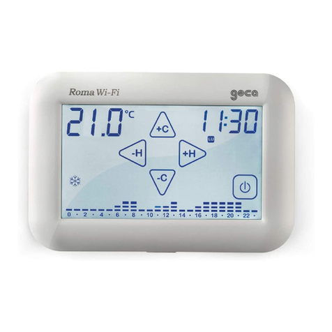
Geca Roma Wi-Fi User manual

Geca

Geca Roma Wi-Fi User manual

Geca Easy Radio User manual

Geca

Geca Easy Radio User manual

Geca Tecno Control T-Touch TE401 User manual

Geca

Geca Tecno Control T-Touch TE401 User manual

Geca T-Touch 503 User manual

Geca

Geca T-Touch 503 User manual

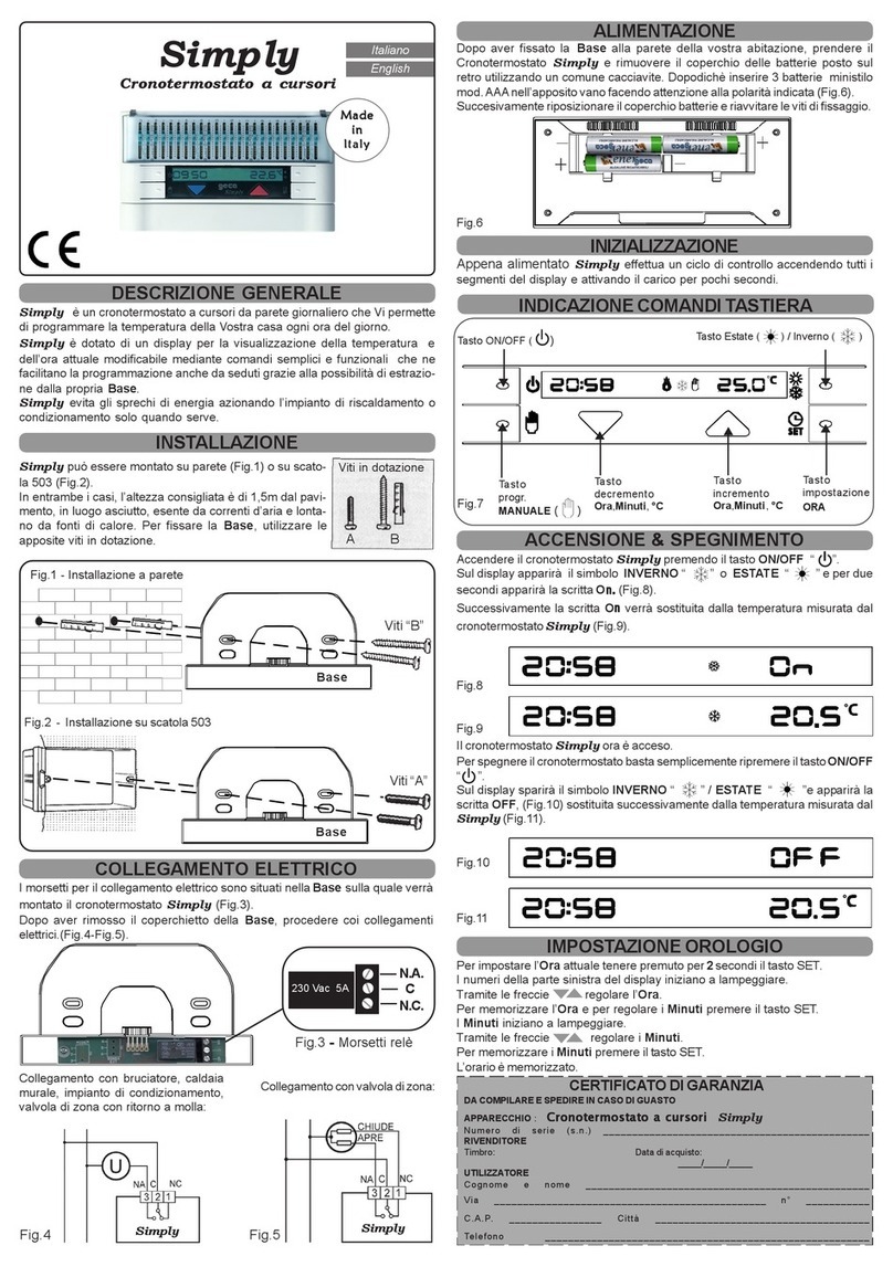
Geca Simply User manual

Geca

Geca Simply User manual

Geca Simply User manual

Geca

Geca Simply User manual

Geca Tecno Control Unico Installation manual

Geca

Geca Tecno Control Unico Installation manual

Geca LIRICO User manual

Geca

Geca LIRICO User manual

Geca Polo User manual

Geca

Geca Polo User manual

Geca Easy 503 User manual

Geca

Geca Easy 503 User manual

Geca Nota User manual

Geca

Geca Nota User manual

Popular Thermostat manuals by other brands

QUBINO FLUSH ON/OFF THERMOSTAT 2 user manual

QUBINO

QUBINO FLUSH ON/OFF THERMOSTAT 2 user manual

Danfoss TP4000 Range installation guide

Danfoss

Danfoss TP4000 Range installation guide

Daintree Networks WTS10 installation instructions

Daintree Networks

Daintree Networks WTS10 installation instructions

Danfoss TP75-RF Installation & commissioning guide

Danfoss

Danfoss TP75-RF Installation & commissioning guide

Robertshaw RS8110 Operation manual

Robertshaw

Robertshaw RS8110 Operation manual

Neomitis RTEORFA installation instructions

Neomitis

Neomitis RTEORFA installation instructions

Pentair HLTSTAT10C instruction manual

Pentair

Pentair HLTSTAT10C instruction manual

Aube Technologies TH114 user guide

Aube Technologies

Aube Technologies TH114 user guide

Popp Smart Thermostat user guide

Popp

Popp Smart Thermostat user guide

White Rodgers 1F94W-71 Operation guide

White Rodgers

White Rodgers 1F94W-71 Operation guide

Stelpro STE302NP user guide

Stelpro

Stelpro STE302NP user guide

Danfoss KPU 19 installation guide

Danfoss

Danfoss KPU 19 installation guide

Lauda Viscotemp 15 G Operation manual

Lauda

Lauda Viscotemp 15 G Operation manual

Siemens RDF310.2/MM manual

Siemens

Siemens RDF310.2/MM manual

COSA SMART ALARKO installation guide

COSA SMART

COSA SMART ALARKO installation guide

Heatmiser PRT-UWTS manual

Heatmiser

Heatmiser PRT-UWTS manual

DEVI Devilink FT installation manual

DEVI

DEVI Devilink FT installation manual

Tekmar 538 user manual

Tekmar

Tekmar 538 user manual

manuals.online logo
manuals.online logoBrands
  • About & Mission
  • Contact us
  • Privacy Policy
  • Terms and Conditions

Copyright 2025 Manuals.Online. All Rights Reserved.