manuals.online logo
Brands
  1. Home
  2. •
  3. Brands
  4. •
  5. Geca
  6. •
  7. Thermostat
  8. •
  9. Geca Tecno Control T-Touch TE401 User manual

Geca Tecno Control T-Touch TE401 User manual

INSTALLATIONINSTALLATION
INSTALLATION
The thermostat must be installed directly into the 3 module pattress box
(flush-mounted installation). The recommended height from the floor is 1.5
metres in a dry place without air currents and far away from heat sources.
1 Carry out the electrical connection as in Pic. 2.
2 Choose the holder plate to utilise on the basis of requirements (SWITCH
PLATE “A”, SWITCH PLATE “B”, SWITCH PLATE “C” or SWITCH PLATE “D”).
3Adapt the attachment of the holder plate on the basis of the required switch
plate.
4 Attach the holder plate to the base of the thermostat’s housing.
N.B. T-Touch: Thanks to the holder platethe most diffused domestic series
of switches and accessories on the market can be mounted and easily adapted.
Pic.1
Connection to the burner, wall-
mounted boiler, air-conditioning
system and the spring return zone
valve:
Connection to the zone valve.
Pic.2
HOLDER PLATE AHOLDER PLATE A
HOLDER PLATE A
Using this holder platethe following domestic switch series can be mounted
1• AVE Banquise and Noir series.
2• VIMAR Idea and Rondò series.
3• BTICINO Living International, Light, Light Tech and Matix series.
1 • Switch plate for the AVE Banquise and Noir series.
No modification is necessary to holder plate A(Pic.3) for its assembly.
Pic. 3
2 • Switch plate for the VIMAR Idea and Rondò series.
Using cutters on the section indicated in the figure, remove a part of all four
attachments of the thermostat’s housing (Pic.4).
Pic. 4
3 •Placca BTICINO serie Living International, Lighte Matix
Using cutters on the section indicated in Pic.5, completely remove all four
attachments of the thermostat’s housing.
Pic. 5
HOLDER PLATE BHOLDER PLATE B
HOLDER PLATE B
Pic. 6
Using this backplate the following domestic switch series can be mounted:
1• VIMAR Plana and Eikon series.
2• BTICINO Luna series.
N.B. For the BTICINO Luna series switch plate use cutters to remove the
two tabs inside the switch plate.
3• LEGRAND Vela series.
No modification is necessary to the backplate for their assembly.
3.530.1652 TE401 White
3.531.1653 TE402 Anthracite grey
3.531.1705 TE403 Silver
U
NA C NC
3 2 1
CHIUDE
NA C NC
3 2 1
APRE
ADAPTABLE SWITCH PLATESADAPTABLE SWITCH PLATES
ADAPTABLE SWITCH PLATES
AVE : serie Banquise and Noir.
VIMAR: serie Idea, Idea Rondò, Plana ed Eikon.
BTICINO: serie Living international, Light, Light Tech, Matix, Luna and Axolute.
LEGRAND: serie Vela.
GEWISS: serie Chorus One, Chorus Lux, Chorus Art, Chorus Flat, Chorus
Geo, *Playbus and *Playbus young.
GENERAL DESCRIPTIONGENERAL DESCRIPTION
GENERAL DESCRIPTION
T-Touch is a flush-mounted touch screen thermostat that facilitates setting
the temperature in your home.
T-Touch allows the setting of two modes of temperature:
The DAYtemperature ( ) and the NIGHT temperature ( 

).
T-Touch has a backlight display with constant digital visualization of the
measured temperature and the set temperature.
T-Touch controls the heating and air-conditioning systems.
It avoids wasting energy by activating the heating and air-conditioning systems
only when required.
Thanks to the holder plate the most diffused domestic series of switches
and accessories on the market can be mounted.
ELECTRICAL CONNECTIONELECTRICAL CONNECTION
ELECTRICAL CONNECTION
The terminals for the electrical connections are positioned at the rear of the
thermostat’s housing (Pic.1).
UK
COLORCOLOR
COLORCOLOR
COLOR
FLUSH-MOUNTED TOUCH SCREEN THERMOSTAT
T-Touch
MadeMade
MadeMade
Made
inin
inin
in
ItalyItaly
ItalyItaly
Italy
T-Touch T-Touch
*OPTIONAL
On request, the T-Touch thermostat can be fittedinto a three-module
backplate (Pic. 8) that permits mounting the GEWISS “Playbus” and
“Playbus young” domestic switch series.
BACKPLATE CBACKPLATE C
BACKPLATE C
BACKPLATE DBACKPLATE D
BACKPLATE D
Using this backplate the following domestic switch series can be mounted
(Pic. 9):
1• GEWISS Chorus One, Chorus Lux, Chorus Art, Chorus Flat and
Chorus Geo series
2• BTICINO Axolute series.
No modification is necessary to the backplate for their assembly.
Pic. 9
D
Pic. 8
To complete the assembly of the thermostat, mount the desired switch plate.
INSTALLATION OF THE THERMOSTAT’S HOUSINGINSTALLATION OF THE THERMOSTAT’S HOUSING
INSTALLATION OF THE THERMOSTAT’S HOUSING
After choosing an adequate backplate fixit into the base of the thermostat’s
housing. Fix the thermostat’s housing into the three-module pattress box
utilizing the supplied screws. The thermostat’s housing is now ready to receive
the thermostat module and then the required switch plate (Pic. 10).
Pic.7
Pic.10
If the thermostat is in STAND-BY ON (Pic.14A) touch the display to enter into
the PROGRAMMING interface (Pic.14B).
Press the display on TEMPERATURE DETECTED (Pic.14C) for 2 seconds,
to enable editing of the program SUMMER/WINTER.
Press the button that appears on the display high up and on the left (SUMMER/
WINTER PROGRAMME in Pic. 21) to modify the programme (Pic.14D).
If the thermostat is in STAND-BY ON (Pic.15A) touch the display to enter into
the PROGRAMMING interface (Pic.15B).To switch off the thermostat keep
the ON/OFF button pressed that is high up and to the right on the display
(Pic. 21) for approximately two seconds. The thermostat goes into shutdown
phase (Pic. 15C) disenabling the operattion of the system and going into
STAND-BY OFF mode (Pic. 15D).To switch on the thermostat it is
firstnecessary to enable the ON/OFF button (Pic. 21) by touching the display
(Pic. 15C). Keeping the button pressed for approximately two seconds, the
thermostat switches on (Pic. 15E) and goes into PROGRAMMING mode
(Pic. 15B).
ON/OFF FUNCTIONON/OFF FUNCTION
ON/OFF FUNCTION
N.B. If the thermostat must receive AVE Banquise or Noir, VIMAR Idea or
Rondò or BTICINO Matix switch plates, insert adequate slot fillerstrips
supplied (Pic. 7) in the appropriate side slots.
The RESET function is necessary to activated the SUMMER / WINTER key
and then simultaneously press and or and .
To activate SUMMER / WINTER key press the display on TEMPERATURE
DETECTED for around 2 seconds. (Pic.14).
The thermostat is powered by two ordinary 1.5V
AA alkaline batteries that ensure its functioning
for at least two years (in STAND-BY mode). Insert
the batteries into the appropriate compartment
situated in the lower part of the module ensuring
that the polarity indicated on the plastic is
followed (Pic. 11). Pic.11
POWER SOURCEPOWER SOURCE
POWER SOURCE
SWITCHING ON/RESETSWITCHING ON/RESET
SWITCHING ON/RESET
After inserting the batteries and initiating the RESET function, the thermostat
carries out a control cycle switching on all segments of the display and
activating the charge for a few seconds (Pic. 12A). The PROGRAMMING
interface appears (Pic. 12B) and after a few seconds the thermostat positions
itself in STAND-BY ON (Pic. 12C).
Pic.12 A Pic.12 B Pic.12 C
The function DAY& NIGHT (Pic. 13B) allows to change with facility the
DAY“ ” temperature with NIGHT “

” temperature.
The degrees set are kept in memory up to following changes.
To increase or to decrease the degrees both in DAYand in NIGHT form press
keys or .
DAYMODE ( ) It is used during the day.
NIGHT MODE ( 

) it is used at night.
Pic. 13A Pic. 13B
To increase or decrease the temperature DAY or NIGHT in the set mode
press the keys or .
To change the operating mode, press the enabled key DAY or NIGHT.
During the STAND-BY ON phase the display will show the symbol of the set
mode with its memorized temperature.
DAY & NIGHT MODEDAY & NIGHT MODE
DAY & NIGHT MODE
SUMMER WINTER PROGRAMMINGSUMMER WINTER PROGRAMMING
SUMMER WINTER PROGRAMMING
Pic.14C
Pic.14A Pic.14B
Pic.14D
PROGRAMMING interface
SUMMER/WINTER
PROGRAMMING
Pic.16D
Pic.17A Pic.17B Pic.17C
ANTI-FREEZE FUNCTIONANTI-FREEZE FUNCTION
ANTI-FREEZE FUNCTION
When the thermostat is switched off the ANTI-FREEZE FUNCTIONremains
active.
If the ambient temperature detected drops below 7°C (7°C – 0.2°C = 6.8°C)
the thermostat activates the heating system to maintain the water in circulation
and stop ice from forming in the tubes (Pic. 18).
Pic.18
BATTERY DISCHARGEDBATTERY DISCHARGED
BATTERY DISCHARGED
The thermostat detects two discharge thresholds of the batteries.
On reaching the FIRST THRESHOLD the symbol of a DISCHARGED
BATTERY(Pic. 21) appears and maintains unaltered the instrument’s functions
(Pic. 19A). On reaching the SECOND THRESHOLD the thermostat switches
off, disenabling the operation of the heating system and flashing theBATTERY
DISCHARGED symbol (Pic. 19B). To reset the functions of the T-Touch
thermostat it is necessary to substitute the batteries.
THERMAL DIFFERENTIALTHERMAL DIFFERENTIAL
THERMAL DIFFERENTIAL
SYSTEM ACTIVATION CONTACTSYSTEM ACTIVATION CONTACT
SYSTEM ACTIVATION CONTACT
The activation or deactivation of the cooling/heating system occurs when the
programmed temperature thresholds are reached via the commutation of the
appropriate contact situated in the thermostat’s housing fitted into the wall.
When touching the display whilst in STAND-BY ON mode (Pic. 20A) and
PROGRAMMING mode (Pic. 20B) the thermostat updates the status of the
contact in the thermostat’s housingto the current status of activation of the
system. This action is verifiable by a brief flash of theSYSTEM FUNCTIONING
symbol ( ). In the absence of an intervention by the user the instrument
updates the status of the contact once an hour.
Pic.20A Pic.20B
BLOCKING FUNCTIONBLOCKING FUNCTION
BLOCKING FUNCTION
It is possible to pass from STAND-BY ON mode (Pic.16A) to the
PROGRAMMING interface (Pic.16B) by simply touching the display.
The thermostat can be blocked in S TAND-BY ON mode by keeping the
and buttons pressed for approximately two seconds. When
the blcabbreviation (Pic. 16C) appears release the keys and the thermostat
goes into blocking mode (Pic. 16D).
To unblock the thermostat keep the display pressed on the blc abbreviation
for approximately 5 seconds (Pic. 16D) and the PROGRAMMING interface
will appear (Pic. 16B).
The THERMAL DIFFERENTIAL is the interval of the thermostat’s intervention
centred upon the SET TEMPERATURE to be reached (Pic. 21). It is quite
wide on the basis of the variability index of the ambient temperature (size of
the environment and influences of the external environment).
In the WINTER ( ) programme the thermostat activates the heating
system when the temperature is detected in the environment:
SET TEMPERATURE - SEMI_THERMAL DIFFERENTIAL
The heating system is switched off when the temperature is detected in the
environment:
SET TEMPERATURE + SEMI_THERMAL DIFFERENTIAL
Vice versa, in theSUMMER ( ) programme the cooling and/or air-conditioning
system is activated when the temperature is detected in the environment:
SET TEMPERATURE + SEMI_THERMAL DIFFERENTIAL
The cooling and/or air-conditioning system is then switched off when the
detected temperature is:
SET TEMPERATURE – SEMI_THERMAL DIFFERENTIAL
The THERMAL DIFFERENTIAL is preset in the thermostat at 0.4°C for the
WINTER ( ) programme and 0.8°C for the SUMMER ( ) programme.
For example:
Programme: WINTER ( )
SET TEMPERATURE: 20.0°C
THERMAL DIFFERENTIAL: 0.4°C
DETECTED TEMPERATURE: 20.0 – 0.2°C =19.8°C HEATING SYSTEM
ON
DETECTED TEMPERATURE: 20.0 + 0.2°C =20.2°C HEATING SYSTEM
OFF
To modify the THERMAL DIFFERENTIAL (d.t.) in the PROGRAMMING
mode Pic. 17B), lightly press the SET TEMPERATURE (Pic. 21) touch area
on the display for approximately three seconds.
On the display appears the abbreviation “d.t.” and amongst the lower figures
appears the d.t. value currently set for the relative programme (Pic. 16C).
The d.t. can then be adjusted between 0.2°C - 2°C using the or
buttons.
GENERAL GUARANTEE CONDITIONS
THIS CERTIFICATE IS THE ONLYDOCUMENT THAT GIVES THE
RIGHT TO HAVE THE PRODUCT REPAIRED UNDER GUARANTEE
- The product is GUARANTEED for a period of 24 months from the purchase
date.
- Any damage occurring from tampering, incorrect and improper use and
installation are not covered by the GUARANTEE.
- The GUARANTEE is valid only if duly compiled.
- In the event of defects covered by the GUARANTEE, the manufacturer will
repair or substitute the product free of charge.
SERVICES OUTSIDE THE GUARANTEE:
Once the terms or the duration of the GUARANTEE have expired, any
eventual repairs will be charged based upon the parts substituted and the
labour cost.
Pic.16A Pic.16B Pic.16C
Pic.15A Pic.15B Pic.15C
Pic.15D Pic.15E
Pic.19A Pic.19B
CERTIFICATE OF GUARANTEE
TO BE COMPILED AND SENT IN THE EVENT OF AFAULT
INSTRUMENT: T-Touch Touch Screen Thermostat
Serial number:_________________________________________
RETAILER
Stamp: Purchase date:
_______/________/________
USER
Surname and name_____________________________________
Address_____________________________________nr_______
Postal code:_______________Town________________________
Telephone____________________________________________ The manufacturer reserves the right to make any aesthetic or functional
modifications without any prior notice and at any time.
dis. 1834043b cod. 2.710.2392
TEMPERATURE
DETECTED
SET
TEMPERATURE
ON/OFF
SUMMER/WINTER
PROGRAMME
TEMPERATUREDECREASED SET
TEMPERATURE AND THERMAL
DIFFERENTIAL
HEATING/AIR-
CONDITIONING
SYSTEM
FUNCTIONING
BATTERY
DISCHARGED
Pic.21
TECHNICAL CHARACTERISTICSTECHNICAL CHARACTERISTICS
TECHNICAL CHARACTERISTICS
-Power source:2 x 1.5V AA alkaline batteries.
-Autonomy (Stand-by): more than 2 years.
-Temperature range adjustment:SUMMER programme
from 15°C to 35°C in the DAYmode “ ”
from 10°C to 30°C in the NIGHT mode “ 

”.
WINTER programme
from 5°C to 30°C in the DAYmode “ ”
from 2°C to 25°C in the NIGHT mode “ 

”.
-Automatic control of the battery discharge with two intervention thresholds.
-Adjustment steps:0.2°C in the WINTER programme ( ), 0.5°C in the SUMMER programme ( ).
-Adjustable thermal differential: from 0.2°C to 2°C (intervention interval from +0.1°C to +1°C )
-Possibility of programming any temperature included in the adjustment fields at each hour of the day, every day of the week.
-Contact capacity:230VAC - 5A (resistive load).
-Installation:fitted into a three-module pattress box.
-Colours available:white, anthracite grey and silver.
-Weight:110gr including the batteries.
GECA Srl via E.Fermi n°98 25064
Gussago (BS) Italy
Tel. +39 030 3730218 - +39 030 3730236
Fax +39 030 3730228
E-mail:[email protected] - http://www.cavagnaindustrie.com
Tecnocontrol Srl via Miglioli n°47 20090
Segrate (MI) Italy
Tel. +39 02 26922890 Fax +39 02 2133734
E-mail:[email protected]
http://www.cavagnaindustrie.com
- The programming interface is completely visualized on the front display screen
and it is therefore possible to utilize the thermostat whilst it is fitted
into its thermostat’s housing in the wall.
If the thermostat needs to be programmed extract it from its housing and then
once reinserted update the status of the relay by touching the display to
establish the temperature detected in that environment.
- The pressure used on the display during use and whilst programming must
be light and localized to the zone foreseen for that specific function.
CORRECT UTILISATION AND MAINTENANCECORRECT UTILISATION AND MAINTENANCE
CORRECT UTILISATION AND MAINTENANCE If there is difficulty in touching it is possible to utilize a slender and non-
metallic instrument. If a palm pen is not available, utilize the blunt end of a
pencil, a plastic cap of a pen, a toothpick or a cotton bud.
- The cleaning of the display must be carried out using a soft and dry cloth
without detergents or cleaning liquids/powders and using light pressure
on the display and possibly with the thermostat in BLOCK mode.
DAY & NIGHT
MODE TEMPERATURE
INCREASED SET
TEMPERATURE AND
THERMAL DIFFERENTIAL

This manual suits for next models

5

Other Geca Thermostat manuals

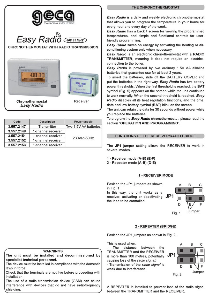
Geca LIRICO User manual

Geca

Geca LIRICO User manual

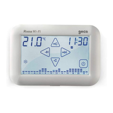
Geca Roma Wi-Fi User manual

Geca

Geca Roma Wi-Fi User manual

Geca Tecno Control Unico Installation manual

Geca

Geca Tecno Control Unico Installation manual

Geca Roma User manual

Geca

Geca Roma User manual

Geca Polo User manual

Geca

Geca Polo User manual

Geca Easy 503 User manual

Geca

Geca Easy 503 User manual

Geca Easy Radio User manual

Geca

Geca Easy Radio User manual

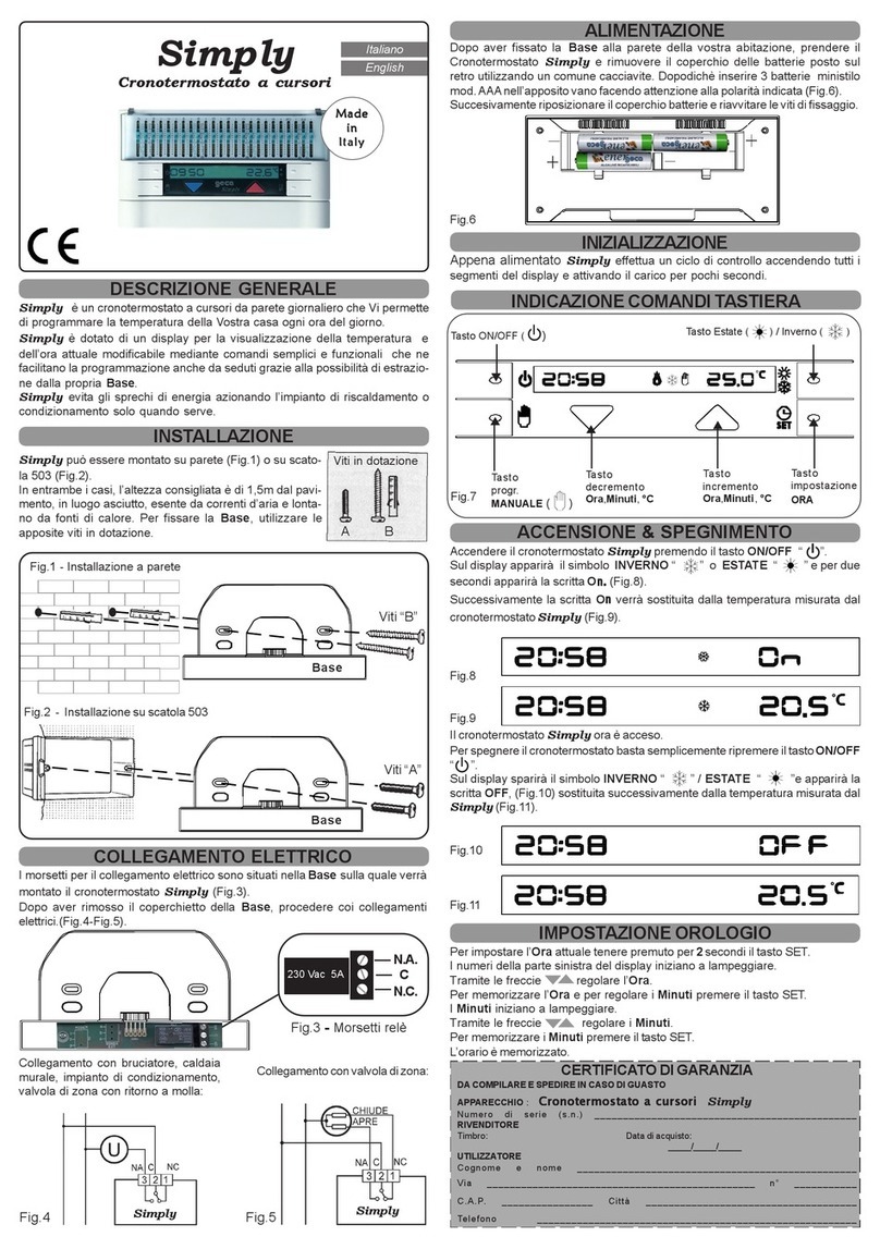
Geca Simply User manual

Geca

Geca Simply User manual

Geca Nota User manual

Geca

Geca Nota User manual

Geca T-Touch 503 User manual

Geca

Geca T-Touch 503 User manual

Geca Simply User manual

Geca

Geca Simply User manual

Popular Thermostat manuals by other brands

Lux Products Ultra 1000 owner's manual

Lux Products

Lux Products Ultra 1000 owner's manual

ICM Controls SC 2000 quick start guide

ICM Controls

ICM Controls SC 2000 quick start guide

TECH Sinum R-S3 quick start guide

TECH

TECH Sinum R-S3 quick start guide

ELRO SF40RV11 manual

ELRO

ELRO SF40RV11 manual

Honeywell CT55N owner's manual

Honeywell

Honeywell CT55N owner's manual

ICM Controls SC 2000 Installation, operation & application guide

ICM Controls

ICM Controls SC 2000 Installation, operation & application guide

Bosch EasyControl Installation and operating instructions

Bosch

Bosch EasyControl Installation and operating instructions

International Refrigeration Products MEDALLION Series Installation & operating instructions

International Refrigeration Products

International Refrigeration Products MEDALLION Series Installation & operating instructions

Agilent Technologies 1100 Series Reference manual

Agilent Technologies

Agilent Technologies 1100 Series Reference manual

tempio HY603 user manual

tempio

tempio HY603 user manual

THERMOFOL TF-H6 operating manual

THERMOFOL

THERMOFOL TF-H6 operating manual

Hunter Internet Thermostat Installation guide and user's manual

Hunter

Hunter Internet Thermostat Installation guide and user's manual

Radio Thermostat CT100 Operation guide

Radio Thermostat

Radio Thermostat CT100 Operation guide

Kampmann 148916 quick start guide

Kampmann

Kampmann 148916 quick start guide

emerio TFN-214472.1 instruction manual

emerio

emerio TFN-214472.1 instruction manual

Honeywell Home Y87RF installation guide

Honeywell Home

Honeywell Home Y87RF installation guide

DELTA DORE TYBOX 23 manual

DELTA DORE

DELTA DORE TYBOX 23 manual

Ariston 3318590 Assembly and operation instructions

Ariston

Ariston 3318590 Assembly and operation instructions

manuals.online logo
manuals.online logoBrands
  • About & Mission
  • Contact us
  • Privacy Policy
  • Terms and Conditions

Copyright 2025 Manuals.Online. All Rights Reserved.