Gecko Compact Operational manual

Gecko
For all models: Compact, Rugged, Blast, Tremor, Prism, SMA & SMA-HR
Seismographs, Accelerographs
Recorders, Vibration Monitors

Welcome to the world of simplified seismic recording with your new Kelunji Gecko
seismograph. Within minutes you can be recording earthquakes, blasts and other ground
vibrations using our latest generation instrument that takes high dynamic range, high
sample rate, low power, continuous recording into new territory.
In the Gecko, we have reinvented the modern digital seismograph. The low cost of flash
memory means you can save weeks, months, even years of continuous data on a single
memory card. The Gecko can record everything continuously while logging trigger times for
you to sort through back at the lab. Even if your trigger settings missed the event, you’ll
always be able to retrieve that chunk of time from the continuous archive.
An even more efficient way of managing your data is not to have to collect it at all, so we
have included a simple telemetry protocol that streams data packets over the Internet via a
cellular data modem or Ethernet link. Data from all of your stations is then available in a
single archive for you to access whenever you need it. Simply install our free “Live Stream”
data reception software on your Windows, Mac or Linux PC and watch your data live on
screen while it is archived away to your PC. Live Stream is ideal for collating data from
multiple network-connected structural monitoring instruments. Download it free today from
the SRC website: https://www.src.com.au/downloads/live-stream/
Our “Waves” waveform analysis application is available as a free download for Windows,
Mac and Linux from http://www.src.com.au/downloads/waves/ . Each Gecko purchased is
entitled to one Waves product key that will remove the advertisement that pops up for 10
serial number to obtain a product key. Each product key can only be used once and is not
transferable to another computer.
Happy recording!
From the Gecko development team.

Table of Contents
Getting Started .................................................................................1
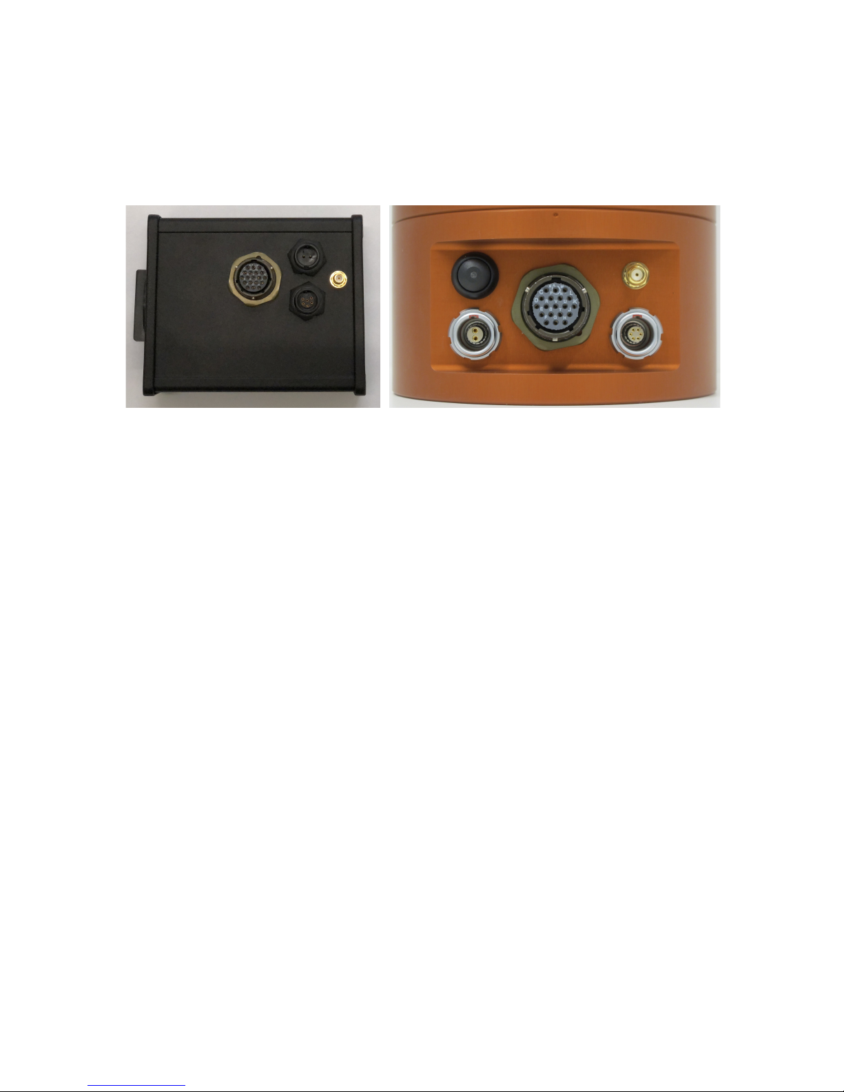
Setting up your recorder .....................................................................................1
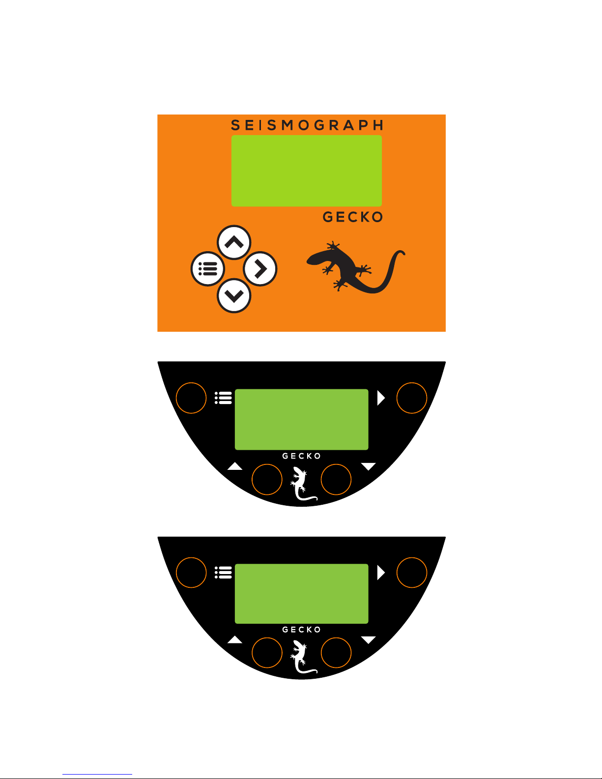
The User Interface ..............................................................................................2
Menu Map............................................................................................................3
The Home Screen..............................................................................4
Status Screen Loop – Right Button ......................................................................4
Realtime Data Loop – Up Button..........................................................................5
Sensor Signal .................................................................................................... 5
Vector Sum ....................................................................................................... 5
Raw Signal ........................................................................................................ 5
The Main Menu..................................................................................6
Unmount SD card ................................................................................................6
Data Storage ..................................................................................................... 7
Station Info.........................................................................................................7
Station Code ..................................................................................................... 8
Network Code....................................................................................................8
Location ID ....................................................................................................... 8
Sample Rate ........................................................................................................9
Channels to Store ..............................................................................................10
Channels to Send ..............................................................................................10
Sensor Setup.....................................................................................................10
3D Sensor....................................................................................................... 10
External 1D Sensor .......................................................................................... 13
Input Amplifier..................................................................................................14
Trigger & Alarm.................................................................................................15
Level Triggering ............................................................................................... 15
STA/LTA Triggering .......................................................................................... 16
Alarm Outputs ................................................................................................. 17
System Alerts .................................................................................................. 17
On-screen Alerts .............................................................................................. 18
Telemetry..........................................................................................................18
Mode.............................................................................................................. 19
Device ............................................................................................................ 19
3G modem Settings.......................................................................................... 19
Settings File ......................................................................................................20
Start Calibration................................................................................................20

Data Storage and Formats ..............................................................21
The Root Directory ........................................................................................... 22
The Data Folder ............................................................................................... 22
The Histogram Folder ....................................................................................... 23
MiniSEED files ...................................................................................................23
Upgrading the Gecko firmware..........................................................................24
Ports & Wiring ................................................................................24
Power connector ...............................................................................................24
Alarm & Communications port...........................................................................25
4D Sensor port (2018 Compact & Rugged)........................................................25
1D Sensor port (mid-2019 Blast & SMA) ...........................................................25
Register your Gecko........................................................................26
Warranty ........................................................................................26
Extended warranty............................................................................................26
Appendix A .....................................................................................28
Installing the Gecko Blast or SMA .....................................................................28
Gains, range and clip levels ............................................................................... 29
Installing the Gecko SMA-HR ............................................................................30
Calibrating a Gecko SMA-HR .............................................................................. 32
Installing the Gecko Tremor..............................................................................32
Installing the Gecko Prism ................................................................................33
Checking Sensor Operation................................................................................ 33
Appendix B .....................................................................................34
Internal Battery ................................................................................................34
Charge Regulator ..............................................................................................35
LED Patterns (routine) ...................................................................................... 35
LED Patterns (exceptions) ................................................................................. 35
Appendix C .....................................................................................36
Perle IOLAN DS1 Ethernet Adaptor ...................................................................36
Change IP address of the Ethernet adaptor.......................................................37
Define IP address of Kelunji Hub computer .......................................................38

1
Getting Started
All Gecko models have a 2-pin power port, 6-pin alarm/communications port, and a coaxial
GPS aerial connection. From mid 2019 Gecko Blast & SMA models also have a 4-pin port for
an external sensor channel. Gecko Compact & Rugged have a 19-pin sensor connection.
Setting up your recorder
The two-pin connector is the power input to the Gecko. The default Gecko operating voltage
range is 11.5 and 24 Volts DC (useful for 12V DC battery over-discharge protection), but it
can be factory switched to extend the range to 7V to 30V DC at no cost. If the power is
removed then restored, the Gecko will restart using the saved settings.
The Gecko only takes a few seconds to initialise the operating system after power is applied.
If an SD card is installed, the recorder will start storing continuous data to the SD card
within seconds.
The small gold coaxial socket is the connection for the GPS aerial. The GPS is crucial in
maintaining accurate absolute time to synchronise recordings from various instruments and
monitoring locations, but it also provides global position information. Simply screw the GPS
cable plug onto the threaded GPS socket until finger-tight.
The Gecko Compact and Rugged is supplied with a sensor plug which you can attach to your
sensor cable. You can find the wiring diagram at the end of this manual. Align the keyed
plug with the socket and push it on, locking it in place with the bayonet-style collar.
At this point you now have a fully functioning recorder, but you will need to modify some
settings to suit your application. Setting a unique station code is an essential starting point.

2
The User Interface
The Gecko does not require a computer to control it. All recorder settings are accessible
through the LCD and are modified using the four control buttons.
Gecko Compact (above)
Gecko Rugged; and Gecko Prism, Tremor & Blast velocity sensors (above)
Gecko SMA, SMA-HR, and Prism acceleration sensors (above)
SEISMOGRAPH
RIGHT
MENU
(LEFT)
UP DOWN
ACCELEROGRAPH
RIGHT
MENU
(LEFT)
UP DOWN

3
Menu Map
After start-up, pressing the Menu button will toggle between the main menu and the home
screen. The LCD backlight will stay on for 2 minutes from the last button press.
On most screens you can scroll Up and Down through a list and enter a menu item or
toggle a setting by using the Right button. Pressing the Menu button will save the current
setting and take you back one menu level.
E: -2,726 0.6
N: 4,326 0.8
Z: -698 0.7
O: 12,356 1.2 *1
p
3D 0.1234567 mm/s
max 11.1234567 mm/s
1D 80.2123546 dB *1
max 101.1234567 dB *1
p
2019-04-01 11:52:18
E: -0.0439408 mm/s
N: 0.0360011 mm/s
Z: -0.0011021 mm/s
p
Home Screen Info & Telemetry 3D Sensor Info GPS location information
2019-04-01 11:52:16 Volt: 14.06 500sps
3D Sensor Name & S/N
*2 Lat: -37.8189800
GECKO Storing ENZO+ uTemp: 35.5° x512 uGecko Blast uLong: 145.0109620
GPS:04 Sending ___O+ #2000343 v4.2.4271 586-H2 586-H1 586-V3 Sats: 12 Alt: 22m
32GB free:92.23495% Connected to Server Type: Acceleration hAcc: 10m vAcc: 19m
Main Menu Station Information Save Continuous Data 3D Sensor
Unmount SD card Station Code Channel E: On Sensor Name
> Station Info > Network Code Channel N: On > Units
Sample Rate Location ID (3D) Channel Z: On Sensitivity ch E
Channels to Store Location ID (1D) *1 Channel O: On *1 Sensitivity ch N *5
Channels to Send 3D Vector: Off Sensitivity ch Z *5
3D Sensor *3
3D Sensor
Auto-Zero Delay *5
1D Sensor *1
Select a Sensor
Cal Enable *5
Input Amplifier > Select a Sensor Custom Sensor Cal Type *5
Trigger & Alarm Sensor Serial No > Geophone 28.8V/m/s Cal Duration *5
Telemetry Mass Lock *5 Geospace GS-1 1Hz Cal Sine Freq *5
Settings File Mass Unlock *5 ...<more> SIG+ Mode: Normal *5
Start Calibration *4 *5 SIG- Mode: Normal *5
Input: DC Offset *5
Communications STA/LTA Triggering
Trigger & Alarm
Enable: Off
Level Triggering
> Mode: Continuous > Threshold
Device: 3G modem > Level STA window size > Enable: Off
TCP Socket Port *6 STA/LTA LTA window size Set Trigger Level
Server IP/Domain *6 Alarm Outputs Filter: 2-20Hz
Carrier APN *6 System Alerts Channel: Z+N+E
Raw Values
Vector Peak
Sensor Signal
Gecko menu appearance will vary by model:
*1 will not appear on 3-channel models
*2 "1D Sensor Info" will show here for 4-channel models
*3 will only appear on Gecko Compact & Rugged
*4 will only appear if sensor has calibration function
*5 will not appear when setting up 4th channel
*6 will only appear for 3G modem on menu re-entry

4
The Home Screen
The home screen shows:
• the Gecko clock’s date and time (in UTC – Universal Time Coordinated)
• station code, and which channels are being stored to the SD card
• number of GPS satellites visible; and channels being sent via Telemetry
• SD card capacity and percentage of storage remaining
2019-04-01 05:52:16
GECKO Storing ENZO+
GPS:04 Sending ___O+
32GB free:92.23495%
“O” is the 4th channel on some Gecko models, and “+” is the vector sum of channels ENZ.
The “Storing” word animates using qdown arrows to indicates packets of data for the
displayed channels are being written to the SD card. The “Sending” word animates using p
up arrows to indicate packets of data for the displayed channels are being streamed to a
remote computer.
Status Screen Loop – Right Button
Version 4 of the Gecko firmware expands the status line to several status pages. These are
shown on the Menu Map within the blue area. Press the Right button to scroll through
them, or press the Menu/Left button to return to the Home screen.
• The first screen shows input power voltage and CPU temperature, the current sample
rate and input amplifier (gain) setting, followed by the Gecko serial number and
firmware version number. The firmware version now integrates the “build” number.
If telemetry is enabled, the bottom line shows the connection status
• The next screen shows the name and serial number of the 3D sensor connected to
channels ENZ. The sensor type is shown on the bottom line
• If you have a 4-channel recorder, the next screen shows the 1D sensor information
• The final screen shows the GPS location information. The “hAcc” value is the
horizontal accuracy value of the GPS aerial position in metres as read from the GPS
receiver, and “vAcc” is the vertical accuracy.
Home Screen Info & Telemetry 3D Sensor Info GPS location information
2019-04-01 11:52:16 Volt: 14.06 500sps
3D Sensor Name & S/N
*2 Lat: -37.8189800
GECKO Storing ENZO+ uTemp: 35.5° x512 uGecko Blast uLong: 145.0109620
GPS:04 Sending ___O+ #2000343 v4.0.4234 586-H2 586-H1 586-V3 Sats: 12 Alt: 22m
32GB free:92.23495% Connection Status Type: Acceleration hAcc: 10m vAcc: 19m

5
Realtime Data Loop – Up Button
Press the Up button from the Home screen to view real time sensor data.
Sensor Signal
The first screen shows sensor output in real units in real time. These values are calculated
based on the sensor and gain settings. Tap or shake the sensor to see the numbers change.
Pressing the Right button on this screen will prompt you to
press the Right button again to reset the zero level. The
Zero Level is set based on the average signal level over the
next 2 seconds.
If you have a 4-channel Gecko, the date and time line will not be shown, with channel O
appearing at the bottom with its live sensor units values shown as per the settings.
Vector Sum
The next screen Up shows the live vector sum of the 3D sensor, and holds the peak value.
For 4-channel models, the live data from channel O is shown and its peak (max) value held.
Pressing the Right button on this screen will prompt you to
press the Right button again to clear the peak values.
Raw Signal
Pressing Up again will display the raw numbers from the ADC in real time. The values
shown are up to ±8,388,608 counts, which represents a signed 24-bit number.
Pressing the Right button will prompt you to do so again to
confirm a reset of the zero level. If you have a 4-channel
Gecko, the date and time line will not be shown, with
channel O appearing at the bottom.
Another feature of this screen is the ability to view the STA/LTA ratio in real time. The value
at the end of each line is the ratio of the average signal in the short term divided by the
average signal in the long term. When nothing much is happening, this value will sit around
1.0, but a short burst of anomalous signal will increase number. This number may assist
you in determining at what level to set your STA/LTA trigger threshold.
Note: The STA/LTA value will only display if STA/LTA triggering is enabled.
2019-04-01 11:52:18
E: -0.0439408 mm/s
N: 0.0360011 mm/s
Z: -0.0011021 mm/s
3D 0.1234567 mm/s
max 11.1234567 mm/s
1D 80.0360011 dB
max 101.0011021 dB
2019-04-01 11:52:20
E: -2,726 0.6
N: 4,326 0.8
Z: -356 1.2

6
The Main Menu
Pressing the Menu button from the home screen will show you a list of actions and settings
for managing your recorder. The main menu includes some or all of the following items:
Main Menu
Unmount SD card
> Station Info
Sample Rate
Channels to Store
Channels to Send
3D sensor
1D sensor
Input Amplifier
Trigger & Alarm
Telemetry
Settings File
Start Calibration
If you change any settings, they are applied once you exit to the home screen. The settings
are also automatically saved to the recorder’s configuration file.
Unmount SD card
In version 3.2 of the Gecko firmware we removed the option to stop and start data
sampling. Data is being sampled at all times, whether an SD card is present or not, because
data can be telemetered without an SD card. If there is no SD card, backfilling of unsent
data will not be possible.
Before you remove the SD card, you should unmount the SD card so that the system does
not try to write data to the SD card while it is being removed, an action that can corrupt the
file, file system, or SD card.
When you insert an SD card, it will automatically be mounted.

7
Data Storage
The Gecko is supplied with a 32GB SD card, formatted with the FAT file system. Larger
capacity SD cards can be used in the Gecko if they are pre-formatted as FAT (not exFAT).
To remove the card from a Gecko Compact 3ch (above, left) slide open the SD card cover
and press in the SD card to eject it. The SD card faces up, and it cannot be inserted upside-
down. For the Gecko Compact 4ch (above, centre), the SD card cover requires a quarter
turn anti-clockwise before removal. The SD card faces the rear of the recorder.
If you have a Rugged model with optional integrated sensor, unscrew the card cover to
access the SD card slot (above, right). The SD card faces the rear of the recorder.
Insert the SD card into your computer (directly if you have an SD card slot, or via a USB
card reader) and you’ll be able to browse your continuous data files.
To re-insert the card, push the SD card into the socket, ensuring you feel the card spring
back from push-lock. The SD card will automatically mount and recording should resume.
Check that the qarrows are animating over the word “Storing” on the Home screen, which
indicates data packets are being written “down” to the SD card.
Station Info
Every seismic monitoring point needs to have a unique identifier. As part of the MiniSEED
data format standard there are three tiers of identifier – Network, Station, and Location.
Station Information
Station Code
> Network Code
Location ID (3D)
Location ID (1D)

8
Station Code
Important! Please change your station code to a unique code, otherwise data
from all of your stations will be called GECKO and it will be difficult for
you to work out which data files came from which station!
The station code identifies the location of the station. If a location has multiple sensors (e.g.
monitoring a building, or setting up an array of sensors) you can use the same station code
but identify each recording point with a different Location ID.
This station code (default is GECKO) can be up to 5 characters long and can only contain
uppercase letters and numbers. If you wish to use less than 5 characters, end the code with
blank space character. Note that any characters after a blank space will be ignored (e.g. if
you enter “ABC 1” the Gecko will use station code “ABC”).
Enter Station Code
GECKO
A flashing block indicates the cursor position. Use the Up and Down buttons to scroll
through letters and numbers, and use the Right button to move to the next character.
Press the Left/Menu button when on the first character to save and exit.
Network Code
The MiniSEED format allows you to include a two character network code, which can be your
FDSN code. For example, the Seismology Research Centre uses “OZ”, Geoscience Australia
uses “AU”, and the British Geological Survey uses “GB”. You can register for an FDSN code
at fdsn.org, or you can use this field for you own identification purposes.
Location ID
As mentioned above, a seismic monitoring station may have multiple monitoring points, so
rather than coming up with a station code for each, they can all use the same station code
with a unique Location ID. This field is any two character code. For example, if you are
monitoring the basement, middle and top of a building you could use Location IDs of B1,
M1, and T1; or simply 01, 02 and 03.
The default value for channels ENZ is 00, and for 4-channel systems channel O has ID 01.

9
Sample Rate
Some sample rates in the Gecko use an FIR filter to remove
frequencies above the Nyquist frequency, i.e. half the
sample rate, e.g. 50Hz at 100 samples per second (sps).
250, 500, 1000, 2000 and 4000sps do not use FIR filtering.
Scroll to the sample rate you wish to use, then press the
Menu button to exit and apply the new sample rate.
Channel Naming
The naming of channels has been automated in the Gecko based on the selected sample
rate and sensor type, with preset channel names.
The SEED standard states that each channel requires a 3-letter code, where the first letter
indicates the Band Code, the second letter indicates the Instrument Code, and the third
letter is the Orientation Code. Detailed information on this standard can be found here:
https://ds.iris.edu/ds/nodes/dmc/data/formats/seed-channel-naming/
The Gecko will set the first letter of the channel name based on the sample rate:
• B: 40 sps
• H: 100 & 200 sps
• C: 250, 400, 500, 800 sps
• F: 1000, 1600, 2000, 4000 sps
The Gecko will set the second letter of the channel name based on the sensor type:
• H: Velocity Seismometer
• N: Accelerometer
• D: Pressure Sensor (e.g. Microphone)
• J: Rotation Sensor
• Q: Voltage
The Gecko will set the third letter of the channel name based on the channel number:
• E: channel 1, typically used for East, Transverse, or X
• N: channel 2, typically used for North, Radial, or Y
• Z: channel 3, typically used for Up, Vertical, or Z
• O: channel 4, typically used for Outdoor Microphone or an extra Vertical sensor
For example, the vertical channel of 40sps broadband seismograph would be BHZ, whereas
a horizontal channel of a 100sps structural monitoring accelerograph might be HNE or HNN.
The data stored as the vector sum of the 3D sensor is named SUM and will use the same
location ID as channels E, N, and Z to reinforce the association with those channels.
Select Sample Rate
40 sps
> 100 sps
200 sps
250 sps
...<more>

10
Channels to Store
As of firmware version 4.0, the Gecko can now turn off any unused channels to save
storage space, and can store (and send) the vector sum of the 3D channels.
Toggle the channels on or off as required. The 3D Vector
channel is the vector sum of channels ENZ, which can now
be stored and streamed. Note that if a channel is enabled for
telemetry (see next setting below), it will automatically be
stored to the SD card as well to ensure the data is available
for backfill should the communication link drop out.
If all channels are accidentally turned off, the Z channel is automatically re-enabled to
ensure at least one channel is being recorded. Note that if a channel is turned off here, it
will also be turned off in the “Channels to Send” settings – see below.
Channels to Send
You can select which channels to send continuously to your remote server. For vibration
monitoring applications you may choose to send the 3D Vector sum channel continuously,
storing the ENZO channels to be sent if a trigger process is enabled and an event detected.
Toggle the channels on or off as required using the Right
button. Version 4 of the Gecko now allows you to stream the
Vector Sum of channels ENZ instead of the individual
channels, although these channels can still be stored and
telemetered when the Gecko triggers.
Note that if a channel is enabled for telemetry, it will
automatically be turned on in the “Channels to Store” settings as the stored data is required
for backfilling gaps in data telemetry. Disabling a channel in telemetry will not disable that
channel in the “Channels to Store” settings.
Sensor Setup
This section of the user manual applies to Gecko Compact, Rugged, Blast and SMA models only. For all
other models, skip ahead to the Input Amplifier section.
3D Sensor
This menu has items that deal with 3D sensor information
and control. This will not be visible in the Blast or SMA, but
the method same applies for setting up the 1D sensor, so
Blast & SMA users should read this section.
Save Continuous Data
Channel E: On
> Channel N: On
Channel Z: On
Channel O: On
3D Vector: Off
Send Continuous Data
Channel E: Off
> Channel N: Off
Channel Z: On
Channel O: Off
3D Vector: Off
3D Sensor
> Select a Sensor
Sensor Serial No.
Mass Lock
Mass Unlock

11
Select a Sensor
The Gecko has a range of popular sensors settings preloaded into the menu to save users
the trouble of entering all of the parameters that allow the data to be displayed in
engineering units (e.g. mm/s, g, mm, dB, rad/s, etc.) rather than recorder counts.
Select a Sensor
Custom
> Geophone 28.8V/m/s
Geospace GS-1 1Hz
…<more>
Scroll down to the sensor you have connected and press the Menu/Left button to exit and
save. This will copy the selected sensor values to the “Custom” sensor so that you can
adjust the settings for your particular sensor. To do this, re-enter the “Select a Sensor”
menu and scroll up to “Custom” and press the Right button to edit the parameters.
Custom Sensor
If you are connecting a sensor that is not in the predefined list, start from a similar type of
sensor and customise the parameters to match your sensor so that the data is stored with
the basic corrections that can be applied automatically when viewed in Waves.
3D Sensor
Sensor Name
> Type: Velocity
Sensitivity ch E
Sensitivity ch N
Sensitivity ch Z
Auto-Zero Delay
Cal Enable
Cal Type
Cal Duration
Cal Sine Freq
SIG+ Mode: Normal
SIG- Mode: Normal
Input: DC Offset
If a setting has a colon, press the Right button to toggle its value, otherwise Right will
enter a menu to select a setting from a list. In the latter case, edit the parameter using the
Up and Down buttons, and use the Menu/Left button to save and exit.
The Sensor Name is a free text field to help you identify the model you are creating. This
can be up to 20 characters long.

12
The Type of sensor you are using can be toggled between Velocity (where units are defined
in metres per second), Acceleration (g), Pressure (pascal), Rotation (radians per second),
Displacement (metres), and Other (“units”).
Sensitivity can be set per channel, which indicates how many Volts-per-unit your sensor
outputs, e.g. 750V/m/s for a Nanometrics Trillium Compact velocity sensor. Note that
Acceleration units will be saved as V/m/s2in accordance with international standards, but
entered as V/g for convenience as most sensors are specified in this manner.
The Gecko can automatically set the zero signal level after the recorder is powered up. If
your sensor performs a self-test on start-up, or requires some time before it settles, use the
Auto-Zero Delay to define the number of seconds to wait until the start of the zero-level
determination process (a 2-second average) or set the value to zero to disable the signal
zeroing function.
Some sensors have a calibration circuit whereby the recorder can send it a stepped voltage
or sine wave signal, and the components will respond accordingly to show that they are
working as expected. Some sensors require a control signal to tell it to enter calibration
mode – the type of control signal is set under the Cal Enable menu.
The Cal Type defines the type and amplitude of the signal size that is sent to the sensor.
There are four sizes of step voltages and sine waves: small, medium, large and extra large,
which generate amplitudes of about 0.5V, 1V, 5V, 10V respectively.
The Cal Duration is the number of seconds that the sine or step signal is active, which is
normally set to the long period response time of your broad band seismometer, or just a
few seconds for a short period seismometer or accelerometer. A “Step” calibrate will run for
twice the entered value to capture the trailing edge of the step response.
The frequency of the sine wave can also be set in the Cal Sine Freq menu, with available
choices being 1Hz, 5Hz, 10Hz, 50Hz, 100Hz, 500Hz, and 1000Hz.
Previously know as “Input Mode” the SIG+ Mode setting tells the Gecko how whether or
not power needs to be applied to the sensor channel positive wires (pins C, E, G and S on
the Gecko sensor connector). For most sensors, this mode should be set to “Normal”, but if
you are using an IEPE sensor, you can select “25V” which will put a 25V of DC power at
4mA out to the sensor channel.
WARNING!Enabling 25V output to non-IEPE sensors may damage your sensor
Previously known as “Sensor Wiring” the SIG- Mode tells the Gecko whether the sensor
channel negative wires (pins D, F, H & T on the sensor connector) need to be connected to
power ground or not. Most sensors require you to measure the difference between the
positive and negative wires, so the “Normal” setting would be used in most cases. If your
sensor requires the negative channel wire to be connected to power ground (e.g. for IEPE
sensors) then select “Ground”.

13
An new setting introduced in firmware version 4.1 allows manual control of a high pass filter
on the sensor input. This enables a simple circuit that removes the DC offset from sensors
by introducing a low order high pass frequency filter. For most sensors, it is best to leave
this Input setting as “DC Offset”, but if you are using an IEPE sensor or have a sensor that
has a large DC offset, set the Input to “Filtered” to enable the filter which will slowly bring
the signal level down to zero. Do not enable this for long period or broadband
seismometers.
An example of where this Input Filter is important is with the White Industrial Geophones,
which have a signal output between 0V to +5V, where the zero level normally sits at +2.5V.
In this case, much of the -20V to +20V input range of the Gecko is wasted. Running the
Gecko’s Input Amplifier at x4 would effectively stretch the 0-5V to 0-20V, but you would
still only be using the upper half of the Gecko’s dynamic range. By enabling the Input Filter,
the zero level of 2.5V would be brought down to 0V, so the output signal would be -2.5V to
+2.5V. This allows you to use an Input Amplifier setting of x8 to stretch the sensor’s output
from -20V to +20V, using the full dynamic range of the Gecko’s 24-bit resolution.
Sensor Serial No.
A 20-character field is available to record your sensor’s serial number. This information is
stored in the station status text file for future reference. Upper and lower case letters,
numbers, and some special characters are available.
Mass Lock & Unlock
Guralp 3-series seismometers have motorised mass controllers that allow the delicate
sensor components to be locked in place for transport and unlocked after installation. Use
Sensor Lock before moving a sensor (this takes just a few seconds), or Sensor Unlock
when the sensor is in place and ready to start monitoring, or to re-centre the masses.
Issuing this command simply connects one of two pins on the sensor connector to Ground
for 5 seconds, so the feature could be used for other purposes if required.
External 1D Sensor
If you have a 4-channel Gecko Compact, Rugged, Blast or SMA, you can set up your 1D
sensor in a similar way to the 3D sensor. Simply select a sensor from the list and optionally
re-enter the menu to customise its name, units and sensitivity. No other settings are
available for this channel.
1D Sensor
Sensor Name
> Type: Pressure
Sensitivity
Set the sensor serial number using the only other menu option.
The SIG+,SIG-& Input settings of the 1D sensor are the same as set for the 3D sensor.

14
Input Amplifier
The Gecko is, fundamentally, a high speed, high resolution Voltage data logger. It measures
the voltage across each channel’s pair of wires, and it can measure from -20V to +20V DC
at 24-bit resolution. This 40V peak-to-peak range is read as a 24-bit number, producing a
value between 0 and 16,777,216 counts, which equates to 419,430.4 counts per volt.
Input Range
x1 (40Vpp)
> x2 (20Vpp)
x4 (10Vpp)
x8 (5Vpp)
x16 (2.5Vpp)
x32 (1.25Vpp)
x64 (625mVpp)
x128 (313mVpp)
x256 (156mVpp)
x512 ( 78mVpp)
If you are using a sensor with a 40Vpp output (for ±10V differential output sensors, such as
Nanometrics or Guralp seismometers) set the gain to x1.
If you have lower voltage output sensors, use the input amplifier to utilise the full dynamic
range of the Gecko - e.g. ±5V IEPE accelerometers or ±4V MEMS accelerometers (as used
in the Gecko SMA), could use a gain of x4 to stretch those output to ±20V or ±16V
respectively to record at higher resolution. Note that ground offsets will also be amplified.
If you are using a passive sensor (e.g. geophone) you can use even higher gains to see
smaller signals at higher resolution. For example, the Gecko Tremor’s geophones (standard
sensitivity of 78.74 V/m/s) normally have a clip level of 254mm/s, but by using a gain of
x16 you can see smaller signals and get a similar effective sensitivity (1260 V/m/s) and clip
level (16mm/s) as a typical short period active seismometer.

15
Trigger & Alarm
The primary function of the Gecko is as a continuous data recorder, but we realise that
triggering is still required to help find events of interest and to control alarms. The Gecko
has two Level trigger processes and an STA/LTA trigger process that can be enabled and
disabled. The Gecko also monitors some system parameters that can generate an alarm.
Trigger & Alarm
> Level
STA/LTA
Alarm Outputs
System Alerts
The Gecko logs the trigger time to a text file that can be used to help you find the data in
the continuous archive. This “trig.txt” file is located in the top level folder of the SD card.
We have developed a small application that can be copied to the Gecko SD card and run
from a Windows computer that will scan the trig.txt folder and then automatically extract
the continuous data from the archive, creating a discreet file in a folder called “reports” on
the SD card that contains one minute of data before and after the trigger time. At the same
time a PDF report is generated for the triggered event, with files named based on the local
time in your PC. This app simplifies vibration monitoring reporting for non-technical users.
Level Triggering
By default each Level trigger process is OFF, but simply toggle this using the Right button.
Level Triggering
> Enable: On
Set Trigger Level
The Gecko will trigger on the vector sum of the 3D sensor channels. The percentage level of
the trigger threshold will affect the ground motion units displayed on the Set Trigger Level
screen. For accelerometers, the estimated MMI and PEIS intensity that relates to this trigger
threshold will also be displayed.
% of Full Scale
5.00 %
0.10316 g
MMI: VI PEIS: 6
Use the Up/Down buttons to change the number values from 0.01% to 99.99% of the
recorder’s full scale range. The line below will update with the ground motion value based
on the calibrated sensor sensitivity and gain of your Gecko.

16
STA/LTA Triggering
By default the STA/LTA trigger process is OFF. Toggle this ON/OFF using the Right button.
STA/LTA Triggering
Enable: Off
> Threshold
STA window size
LTA window size
Filter: 2-20Hz
Channel: Z+N+E
The Short Term Average (STA) signal level divided by the Long Term Average (LTA) signal
level produces a ratio indicating how much above-average signal is occurring.
Short Term Average
2.0 second
averaging window
If you want to declare and event when the short term average signal level is three times
higher than the long term average signal level, you set the Threshold to 3. The length of
the short term and long term time windows is also user selectable.
The LTA value must be larger than the STA value.
Signal averages can be calculated using the raw data or filtered to suit to local earthquake
detection. On the Filter line, use the Right button to toggle the 2-20Hz filter on or off.
The STA/LTA algorithm can run on any, some, or all of the 3D input channels, which you
can cycle through using the Right button on the last menu item.
A more detailed explanation of the STA/LTA trigger algorithm is provided in our Waves data
analysis application’s user manual. You can visualise the effect of changing the various
STA/LTA settings using Waves.
Other manuals for Compact
1
This manual suits for next models
6
Table of contents
Other Gecko Accessories manuals
Popular Accessories manuals by other brands

Marley
Marley Primus P11 user manual

Moffat
Moffat SDHU OPERATING & SERVICE MANUAL

Pfannenberg
Pfannenberg DTI 9441 Operating & assembly instructions

Lutron Electronics
Lutron Electronics Caseta Advanced features

Seifert
Seifert SlimLine Pro KG 8508 instruction manual

Iget
Iget SECURITY M3P9 installation manual