Geco GC201 Parts list manual

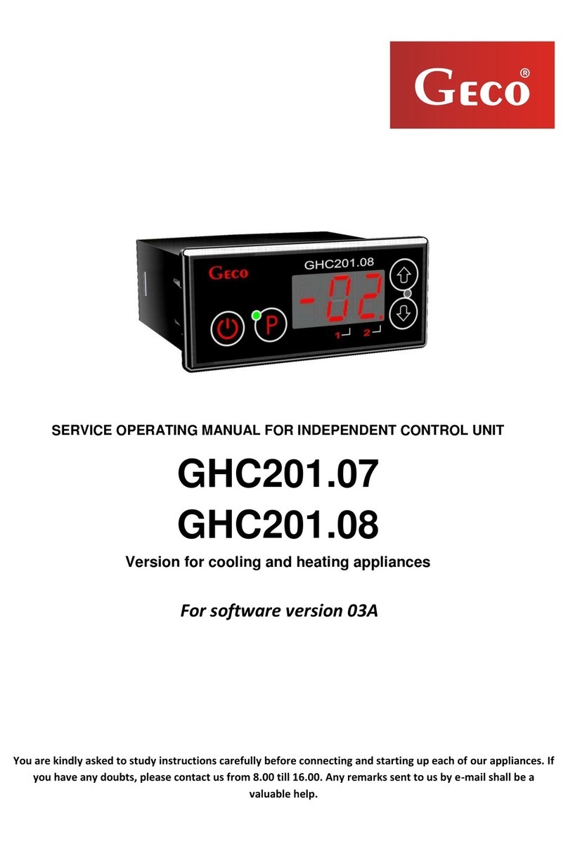
SERVICE OPERATING MANUAL FOR INDEPENDENT CONTROL UNIT
GC201
VERSION FOR COOLING APPLIANCES
For software version 02
You are kindly asked to study instructions carefully before connecting and starting up each of our
appliances. If you have any doubts, please contact us from 8.00 till 16.00. Any remarks sent to us by e-
mail shall be a valuable help.
Notice !!! At the bottom of the following pages the date of the latest updating is given and at
the end of page XVII there is information on the changes in program versions and the mode of
operation that followed.
You are asked to use always the newest version of operating manual which can be received free of
charge by mail after submission of an order.

page 2 SERVICE MANUAL FOR PRODUCERS SBR TYPE GC201
PPUH „GECO” EDITION I PRINTOUT DATE 18-04-30
Table of contents
I. GENERAL CHARACTERISTICS. ................................................................................. 3
II. METHOD OF MARKING AND TECHNICAL DATA ...................................................... 3
III. HOW TO ORDER..................................................................................................... 4
IV. INSTALLATION AND CONNECTION OF GC201 ...................................................... 5
V. INSTALLATION OF SENSORS................................................................................... 6
VI. OPERATION METHOD ......................................................................................... 6
A-GENERAL INFORMATION ................................................................................................. 6
1. Start after connection to mains.............................................................................. 6
2. Functions of buttons............................................................................................... 7
3. Programming of temperature: ............................................................................... 7
4. Signalling of compressor operation........................................................................ 7
5. Compressor protection........................................................................................... 8
6. Alarms of sensors –A1 and A2 ............................................................................... 8
7. Overheating alarm - A4.......................................................................................... 8
8. Temperature monitoring........................................................................................ 8
B-DEFROSTING ................................................................................................................ 9
C–SUPER FROST............................................................................................................... 9
D–HYSTERESIS............................................................................................................... 10
VII. PROGRAMMING OF SYSTEM PARAMETERS ...................................................... 12
VIII. PROBLEMS AND THEIR REMOVAL ..................................................................... 14
IX. RETURNS FOR REPAIR.......................................................................................... 16
X. METHOD OF CONNECTING DEVICES TO THE CONTROLLER................................... 16
XI. INFORMATION ABOUT MARKING AND COLLECTION OF USED ELECTRICAL AND
ELECTRONIC EQUIPMENT .......................................................................................... 20

SERVICE MANUAL FOR PRODUCERS SBR TYPE GC201 Page 3
PPUH „GECO” EDITION I PRINTOUT DATE 18-04-30
I. GENERAL CHARACTERISTICS.
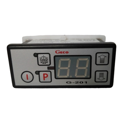
Independent Control Unit called further GC201 is a modern, comfortable and easy to operate appliance.
It was produced using microprocessor technology and automatic surface assembly.
GC201 stabilizes the temperature and controls automatic defrosting. Period of defrosting can be
adjusted to specific ambient conditions. It also has a button for manual defrosting of the evaporator or for quick
freezing of products in the refrigerator. The mode of operation of this button determines the appropriate
parameter.
GC201 has the ability to select work with one or two temperature sensors and has two relay outputs
enabling direct connection for devices operating at 230V with load capacity in accordance with Table 1.
The controller is equipped with sound signaling as standard, which activates when any button is
pressed on the keypad and when an alarm occurs.
In order to provide the user with the comfort of using the controller, capacitive (touch) buttons were
used in the keyboard.
This thermostat does not require special maintenance; the keyboard was made from a special type of foil
resistant to high temperature and most chemicals. It is not permitted to clean it with sharp objects. It is
sufficient to clean the front plate with a wet cloth from time to time.
II. METHOD OF MARKING AND TECHNICAL DATA
Model: GC201.0X
0X –number indicating the version of the controller
01 –two-relay controller with the possibility to configure the device connected to the second relay in the range:
heater / fan / valve. The controller's keypad is made without a light button.
02 - two-relay controller with the possibility to configure the device connected to the second relay in the range:
light / heater / fan / valve. It is a version dedicated to those users who want to use a second relay to control the
light. The controller's keypad keyboard is made with a light button.
03 - single-relay controller controlling the work of a larger power compressor. The controller's keypad is made
without a light button.
04 - one-relay controller controlling the operation of the compressor with a standard 16A relay. The controller's
keypad is made without a light button.
Operating Voltage
230V +10% -15%
Enviroinment Temperature
od +5oC do +40oC
Humidity
od 20% do 80% RH
Protection Level
IP65 Front side of control panel
Sensors type
NTC 2,2kΩ - range: from -400C to +600C

page 4 SERVICE MANUAL FOR PRODUCERS SBR TYPE GC201
PPUH „GECO” EDITION I PRINTOUT DATE 18-04-30
Table 1:Marking of transformers and carrying capacity of outlets
outlet
current-carrying capacity
Ia
Ib
P
version GC201.01 and GC201.02
P1 –Compressor
R16A
4A
cos φ > 0,85
1HP
750W
P2 –Universal
R8A
2A
-
450W
version GC201.03
P1 –Compressor
R30A
8A
cos φ > 0,85
2HP
1500W
version GC201.04
P1 –Compressor
16A
4A
cos φ > 0,85
1HP
750W
Ia –transformer rated current.
Ib –load rated current
P –load rated power.
Notice !!!
Total power consumed at once by appliances may not exceed 10A !!!
III. HOW TO ORDER
In the order you have to give the full name of the controller in accordance with the marking defined in item II
and the length of temperature sensors. Standard length of sensors: 2,5m and 3,0m.
The following types of thermostats are available:
GC201.01 Thermostat that controls operation of the compressor and additional device (heater, fan or valve).
GC201.02 A thermostat that controls work of a compressor and an additional device - mainly lighting or a
heater or a fan or a valve.
GC201.03 A thermostat that controls operation of a larger power compressor.
GC201.04 Thermostat that controls operation of the compressor.

SERVICE MANUAL FOR PRODUCERS SBR TYPE GC201 Page 5
PPUH „GECO” EDITION I PRINTOUT DATE 18-04-30
IV. INSTALLATION AND CONNECTION OF GC201
1. Cut a hole with dimensions 28x70 mm in the appliance in the place marked accordingly.
2. All metal elements through which GC201 or its cables are put should be filed or protected otherwise. I
is not permitted to fix GC201 in a way which allows direct contact with water (e.g. condensing water on
the lower cover of the display), touching of evaporator outlet pipe etc. and causes considerable
changes of its temperature in comparison with air temperature (e.g. fixing in direct vicinity of the
compressor and its accessories, cooling and heated elements).
3. When GC201 is fixed, power cables should be connected in accordance with the description on the
casing. In the case of versions GC201.03 and GC201.04 with one relay, the output of the other relay will
be unused - it will be marked with a cross on the label with the description - no wires should be
connected to these outputs !!!
4. Connectors have certification for permanent load 16A !!! They are provided with fine thread and special
plates preventing cutting of cables, therefore, when lightly screwed together they will have maximally
good contact and if more force is applied, it may damage the thread. In result the socket may be
melted and there might be a short circuit!!!
5. The whole unnecessary length of cables is shortened by cutting or winding and clipping together by
special plastic bands. Cable have to be well-fastened along their whole length and may not touch the
compressor and its accessories.
6. When the appliance is connected to mains, there might be voltage in light cable regardless whether it
is switched on or off with the button therefore, the starter or the fluorescent lamp may be
replaced only when the power cable is unplugged from the socket!!!
THE SAME CONDITION IS VALID FOR ANY OTHER REPAIRS!!!
7. If there are heaters, their voltage has to be chosen in such a way that if there is a breakdown of GC201 or
of an external contactor and they are switched off permanently, there will be no possibility of fire or
destruction of the appliance. If high power heaters are used, safety thermostat must be used on the
evaporator unconditionally. This thermostat should operate on a different basis, e.g. a mechanical
thermostat.

page 6 SERVICE MANUAL FOR PRODUCERS SBR TYPE GC201
PPUH „GECO” EDITION I PRINTOUT DATE 18-04-30
V. INSTALLATION OF SENSORS.
1. For every type of the cooling unit the place of fixing of chamber and evaporator sensor and setting of
system parameters GC201 should be chosen through experimentation. It is absolutely forbidden to change
the location or the method of fixing of sensors and settings of GC201 without doing new tests related to
temperature stabilisation and to the course of defrosting of the unit!!!
2. The chamber sensor must be fixed in such a way that it does not touch foods and is not exposed to damage
during cleaning of the unit. A special plastic handle can be used to fix this sensor. Such solution causes
quick (time delay on/off see VI, item 5) the reaction of the sensor and of the whole thermostat to a change
of air temperature in the unit. If it is recommended or necessary to slow down and ‘smooth out’ reaction
time of the sensor to temperature changes, it is advisable to screw it to a metal element of the unit.
3. Evaporator sensor should be fixed in the way which assures maximally good and sure contact with the
evaporator slat and in the place where ice keeps longest during defrosting. Its fixing should prevent its
pushing out by growing ice. If possible, sensors should be fixed vertically so that the cable goes out of a
sensor at its bottom.
4. Sensor cables can be shortened or lengthened in any way according to the following rules:
-Cable sensor should not be cut at a distance below 0.5 m from the shell
-It is not recommended to lengthen sensor cable above 20 m.
-SENSOR CABLES CAN BE CONNECTED TO SENSOR CLAMPS IN THE OPERATING UNIT IN ANY WAY!!!
(similarly to the method of plugging of the plug in the socket ~230V)
-cable OMY 2x0.5 mm is recommended for cable lengthening,
-if cables are lengthened their connection should be done very carefully, every pair of veins should be
soldered and heat-shrinking sheaths should be put on them. Then the place of connection should be
filled with water-resistant silicone and one more heat-shrinking sheath should be put on..
-endings of cable connected to the independent control unit should be tinned.
VI. OPERATION METHOD
A - General information
1. Start after connection to mains
When the unit is connected to mains a 3-second start procedure takes place during which two dots appear on
the display for a second, controller program version appears for another second and then two dots appear
again. At that time none of controlled units is switched on.

SERVICE MANUAL FOR PRODUCERS SBR TYPE GC201 Page 7
PPUH „GECO” EDITION I PRINTOUT DATE 18-04-30
If the unit was on when power was disconnected, at the end of start procedure it will be on and the value of
temperature in chamber sensor appears on the display.
If it was off, two horizontal lines will appear on the display.
2. Functions of buttons
- When pressed and holded for 5 sec., thermostat is switched on/ off. When you hold down the button, a
rising sound signal is generated.When it is off, two horizontal lines appear on the display.
- When pressed, light is switched on/ off. This is signalled by a green diode at the button.
Button works independently from thermostat switch - .
- It is used for manual activation of defrosting or fast freezing of products depending on the setting of
parameter c4.
- used to program settings and to end programming.
- It is used to increase the set temperature during programming and to switch on the evaporator
temperature display, if the evaporator sensor is operated r2 = 0 (to activate the preview, hold the button
longer).
- It is used to reduce the set temperature during programming and to switch on the chamber temperature
during defrost (to activate the preview, hold the button longer).
3. Programming of temperature:
After pressing programming mode is turned on, the value of a parameter appears on the display and a
diode at the button switches on.
When or are pressed, the value of a parameter changes within the range ‘d0’ – ‘d1’.
When is pressed, settings are memorised and normal operation of the controller follows.
If GC201 is switched off during programming, it will not memorise the new value of temperature.
4. Signalling of compressor operation
When the compressor is on, small red diode (dot) in the right bottom corner of temperature display is on. This
facilitates checking of possible defects of the system.
If the compressor should be switched on and it is not because one of protections has been switched on (see
item 5), the dot which signals operation of the compressor will flash. When the set time of protection ends, the
dot will be lit permanently and the compressor will be switched on.

page 8 SERVICE MANUAL FOR PRODUCERS SBR TYPE GC201
PPUH „GECO” EDITION I PRINTOUT DATE 18-04-30
5. Compressor protection
A delay in switching on of the compressor when the temperature at which it should be on is reached
(temperature set by the user minus the lower value of hysteresis) is 30 seconds. If during that time
temperature falls, condition of excess of 30 seconds is checked again. This is to protect the compressor
against unneeded switching on caused by e.g. placement of goods, drafts, etc.
From the moment when the compressor is switched off for time defined by parameter ‘c2’, GC201 will
prevent compressor from switching on.
After every break in electricity supply or voltage fall below 175V, GC201 will prevent compressor from
switching on for time defined by parameter ‘c2’. However, if ‘c2’=0min, protection will last 30 seconds.
When the unit is connected by the button there is a 5-seconds delay before the compressor is
switched on. It should be emphasised that in this way all other protections are cancelled. Thanks to that,
operation of the compressor can be checked quicker.
6. Alarms of sensors –A1 and A2
The controller is provided with alarms which inform of defects of sensors. A defect of a sensor is
signalled by appearance of a corresponding symbol on the display together with a sound signal. After pressing
any button, the alarm signal is muted.
If an A1 alarm occurs, it is displayed instead of the chamber temperature. In the event of an A2 alarm, the
message is displayed alternately with the chamber temperature. If two sensors fail at the same time, alarms A1
and A2 are displayed alternately.
A1 –damage of chamber temperature sensor. GC201 will connect the compressor in a time cycle (so called:
clock control) according to time defined in parameters ‘c8’ and ‘c9’. Defrosting will function normally.
A2 –damage of evaporator sensor. If parameter r2 = 0 and c0 ≠ -1, the evaporator sensor fault alarm will be
signaled. In this case, the operation of manual and automatic defrost is blocked !!! If we change the parameter
to r2 = 1, then the defrost of the device will be carried out in time according to the setting of the parameter
'c1'.
7. Overheating alarm - A4
If the temperature in the chamber is higher than the 'd6' parameter, an A4 alarm is displayed alternately with
the temperature, and an acoustic signal is generated. After pressing any button, this alarm is silenced.
8. Temperature monitoring
If the parameter r2 = 0, then after pressing and holding button for a longer time the display will start
blinking and show the temperature of the evaporator, after the next 5 seconds the GC201 will automatically
return to the temperature reading from the chamber. Warning!!! This function also works during defrosting
when "dF" lights up in the display. You can also see the temperature from the chamber sensor by pressing and
holding button for a while, the display will start to show (without blinking) the chamber temperature, after
a further 5 seconds GC201 will automatically return to "dF" display.

SERVICE MANUAL FOR PRODUCERS SBR TYPE GC201 Page 9
PPUH „GECO” EDITION I PRINTOUT DATE 18-04-30
B - Defrosting
1. If additional defrosting is necessary in result of difficult conditions of operation and the SF function is
switched off (c4=0), the button should be pressed. Then the green diode will light permanently on the
button and ‘dF’ will appear on the display instead of measurement of temperature. This moment the
unit will begin a defrosting cycle.
2. If defrosting take place and parameter r2=1 then time od defrosting is controlled by parameter ‘c1’. If
defrosting takes place and parameter r2=0 and temperature on evaporator is higher than temperature set in
parameter ‘d2’, after about 10 seconds the unit will begin the end phase of defrosting and after its end it will
start further operation. If defrosting take place and parameter r2=0 and temperature on evaporator is lower
than temperature set in parameter ‘d2’ than GC201 will turn on the defrost mode and after reaching the
temperature from the parameter 'd2' will enter the end of defrosting procedure (this state is signaled by
blinking green LED on the button ) consisting of one dripping phase in which the compressor remains
off for the time specified by parameter 'c3'.
If the time of entering to automatic defrosting mode (time c0) take place during the compressor operation,
the defrost mode will be delayed until the compressor is turned off.
The compressor can be switched off when the set chamber temperature is reached (according to the control
hysteresis) or after exceeding the maximum compressor operation time (for c5 ≠ 0).
If the device cannot reach the set temperature, the maximum compressor operation time in parameter c5
should be extended.
3. If defrosting takes place and temperature on evaporator is lower than temperature set in parameter ‘d2’,
GC201 will switch on defrosting and when temperature in parameter ‘d2’ is reached, the procedure of the
end of defrosting will begin (signalled by a flash of the green diode on the button ) consisting of one
dripping phase in which the compressor is off for time defined by parameter ‘c3’.
4. When ‘dF’ disappears and defrosting is finished, the display shows the temperature that was memorised just
before the beginning of defrosting for the whole time defined in parameter ‘c7’: this is to prevent
complaints because of ‘sudden changes of temperature in the unit’.
5. The unit functions in the same way during manual and automatic defrosting.
C –Super Frost
The function is used to quickly freeze products in the refrigerator. The 'c4' parameter defines the
operating time of the refrigerator in SuperFrost mode (time of continuous compressor operation). It is possible
to set the working time from 1-48h in intervals of 1h. If the parameter c4 is set to "0" then the SF function is
blocked.
If the SF function is blocked, the SF button performs the manual defrost function "dF".
After activating the SuperFrost function, the symbol "SF" appears alternately with the current
temperature preview. The dot on the right side of the display indicates the operation of the compressor.
Continuous lighting - the compressor is working. The dot flashes - waiting for the compressor to start (the
compressor has to work but the minimum compressor standstill condition has not been met). After all the

page 10 SERVICE MANUAL FOR PRODUCERS SBR TYPE GC201
PPUH „GECO” EDITION I PRINTOUT DATE 18-04-30
conditions for compressor activation have been met, the dot is permanently lighted and the compressor relay is
switched on.
Entering the SupeFrost mode:
-When the compressor is working (because it was just in the normal mode of the refrigerator), then the
compressor continues to work, the device is in SF and the dot is lighted continuously,
-If the compressor was turned off and the time of the compressor's minimum stoppage (parameter
"c2") has ended, the compressor is switched on, the device enters into SF mode and the dot is lighted
continuously,
-Otherwise, the display shows SF, the dot blinks and the compressor is not switched on.
Working in SF mode:
-SF lights up on the display, the dot is lighted continuously and the compressor is working until the time
defined by the "c4" parameter counted from pressing the button .
Exiting the SF mode:
-The compressor is switched off, the dot goes out and SF apears on the display until the temperature in
the device will increase to the value at which the compressor is turned off in the normal operating
mode ('Setpoint Temp' - (Hysteresis / 2 rounded to the whole number down 'd3'))
-damage to the chamber temperature sensor was found.
After fulfilling these assumptions, the word "SF" disappears and the display shows the current temperature or
A1 (if the chamber temp sensor has been damaged).
D –Hysteresis
During programming of the parameter ‘d0’ and ‘d1’ (minimal and maximal temperature which can be set by the
client) one should remember that the value of hysteresis ‘d3’ causes additional lowering or increasing of
temperature beyond the temperature sent by the user.
This is particularly important for units with plus temperatures, which should always operate above 0ºC.
Example:
As a producer of cooling equipment, e.g. of a refrigerated display case (plus temperatures) I demand that the
unit allow operation within the range of values given below: off –min: 2ºC, on - max: 10ºC.
symmetrical hysteresis for even
values of‘d3’
asymmetrical hysteresis for odd
values ‘d3’
example 1.
Hysteresis of ‘d3’ is set as 2ºC
For the above setting of the hysteresis the
parameter ‘d0’ should be set as 3ºC and ‘d1’ as 9ºC
example 3.
Hysteresis of ‘d3’ is set as 3ºC
For the above setting of the hysteresis the parameter
‘d0’ should be set as 3ºC and ‘d1’ as 8ºC

SERVICE MANUAL FOR PRODUCERS SBR TYPE GC201 Page 11
PPUH „GECO” EDITION I PRINTOUT DATE 18-04-30
example 2.
Hysteresis of ‘d3’ is set as 4ºC
For the above setting of the hysteresis the
parameter ‘d0’ should be set as 4ºC and ‘d1’ as 8ºC
example 4.
Hysteresis of ‘d3’ is set as 5ºC
For the above setting of the hysteresis the parameter
‘d0’ should be set as 4ºC and ‘d1’ as 7ºC
CHARTS WHICH PRESENT OPERATION OF PARTICULAR ELEMENTS OF THE UNIT
Thick line means that the unit is on and interrupted line means that the unit is off.
The square ‘stop’ means that the compressor is off and ‘operation’ that it is on because programmed
temperature has been exceeded, taking into account the value of programmed hysteresis parameter ‘d3’.
AN ERROR IN THE SETUP OF PARAMERS WILL CAUSE WRONG OPERATION OF THE UNIT!!!
1. ventilator which operates together with compressor ‘r1’=01
t=0 (c3 of no importance)
COMPRESSOR
VENTILATOR
stop operation DEFROSTING END OF DEFROSTING operation stop
2. ventilator which operates all the time ‘r1’=02,
t=0 (c3 of no importance)
COMPRESSOR
VENTILATOR
stop operation DEFROSTING END OF DEFROSTING operation stop
3. evaporator heater ‘r1’=03,
t=c3
COMPRESSOR
HEATER
stop operation DEFROSTING END OF DEFROSTING operation stop
4. tray heater ‘r1’=04,
On temperature
Temperature set
by the user
‘d3’
Off temperature
‘d3’
½‘d3’+0.5ºC
½‘d3’-0.5ºC
½‘d3’
½‘d3’

page 12 SERVICE MANUAL FOR PRODUCERS SBR TYPE GC201
PPUH „GECO” EDITION I PRINTOUT DATE 18-04-30
t=c3
COMPRESSOR
TRAY HEATER
stop operation DEFROSTING END OF DEFROSTING operation stop
5. valve ‘r1’=05,
t=c3
COMPRESSOR
VALVE
stop operation DEFROSTING END OF DEFROSTING operation stop
VII. PROGRAMMING OF SYSTEM PARAMETERS
When the unit is on and correctness of its operation has been checked (factory settings are standard settings),
setting of system parameters of GC201 begins.
In order to do that, the unit must be switched off with the button (two horizontal lines appear on the
screen). Then buttons and
must be pressed and holded. When they are being pressed, the button must be pressed (short sound
signal is activated). All three buttons must be pressed together for about 5 seconds. If any of the buttons is
released at that time, programming will be interrupted. When this activity is done, diodes on buttons and
will flash and symbol ‘c0’ will appear on the display for 1 second. Then the latest programmed value of the
parameter will appear. Now, using buttons the new values should be set; every longer pressing of the
button will cause quick winding of possible settings. Then should be pressed to accept the set data and
start programming of a new parameter.
It is possible to change some settings only if you do not want to change a given parameter, press and
GC201 will move to the next parameter.
After entering the last parameter setting and accepting it with the button , it will automatically exit the
programming mode and return to STANDBY mode (two horizontal lines on the display).
If no button is pressed within 20 seconds, the device will exit the parameter programming mode.
Notice !!!
Producer of cooling equipment can block access to some or to all parameters of the keyboard
using a computer programmer. If so, when an attempt to change settings of a blocked
parameter is made, the symbol ‘bL’ will appear on the display for about 1 second.

SERVICE MANUAL FOR PRODUCERS SBR TYPE GC201 Page 13
PPUH „GECO” EDITION I PRINTOUT DATE 18-04-30
Table 2: Significance of parameters
Para-
meter
Description
Min
Max
Step
Factory setting
c0
How often defrosting will take place
00 –there will be no automatic defrosting, only manual defrosting!!!
-01 there will be no automatic or manual defrosting!!!
-01
24
1h
6h
c1
For r2 = 0 the maximum defrosting time, if the evaporator does not
reach the set temperature (parameter d2); for r2 = 1 defrosting time
not conditioned by parameter d2; Warning!!! If this parameter is set
to "-01" there will be no time limit
-01
99
1min
30min
c2
Minimal time of compressor stoppage
0
15
1min
3min
c3
Time of evaporator dripping
0
15
1min
2min
c5
Maximal time of operation of compressor
0 –no testing (this parameter is off)
0
99
1min
40min
c6
Time of compressor stoppage after switching on of protection from
parameter ‘c5’
0
99
1min
10min
c7
Time during which after the end of defrosting (parameter ‘c3’)
temperature measured just before the beginning of defrosting will
be displayed
0
60
1min
5min
c8
Compressor operation time with damage of control sensor
1
99
1min
25min
c9
Compressor stoppage time with damage of control sensor
1
60
1min
5min
d0
Minimal temperature for a client to set
-40
20
1°C
1°C
d1
Maximal temperature for a client to set
d0+1
40
1°C
10°C
d2
Evaporator temperature at which defrosting will stop
0
40
1°C
5°C
d3
Value of hysteresis
1
10
1°C
2°C
d4
Value of rescaling of chamber sensor in comparison with actually
measured temperature
-10
10
1°C
0°C
d6
Temperature in the chamber whose exceeding makes alarm A4
switch on.
-40
40
1°C
40°C
r1
Unit connected to other transformer:
00 –lighting
01 –ventilator operating with compressor
02 –ventilator operating all the time
03 –evaporator heater
04 –tray heater
05 –valve
06 –compressor transformer with more power - ! equipment
replacement required ! ref. to GC201.03
00
04
1
00
(for version
GC201.02
and GC201.04)
01
(for version
GC201.01)
06
(for version
GC201.03) )
r2
Operation of the evaporator sensor:
0 - the sensor is supported
1 - the sensor is blocked
00
01
1
00

page 14 SERVICE MANUAL FOR PRODUCERS SBR TYPE GC201
PPUH „GECO” EDITION I PRINTOUT DATE 18-04-30
r5
Conditions of switching on of defrosting when the unit is switched
on:
00 –beginning of operation without defrosting
01 –if during defrosting power supply is disconnected, defrosting will
be switched on
02 –defrosting after every switching on of unit power supply
00
02
1
00
VIII. PROBLEMS AND THEIR REMOVAL
Table 3: Problems and method of their elimination
defect symptoms
check
1. Display is not lit
although GC201 is
connected to mains
Check:
- if there is voltage 230V on feeding clamps L and N
2. Compressor does
not switch on
although it is
signalled that it is on:
red diode
Check:
- if there is voltage 230V on clamps P1 and N –If there is voltage, check the
compressor
3. Defrosting heater
does not switch on
Check:
- if there is voltage 230V on clamps as described on the casing of the
controller
- if there is, check the heater
4. Error of
temperature
indication
Check:
- connection of sensors to connectors
- the value of parameter ‘d4’
- if the sensor is fixed correctly
- the condition of the cable of the sensor: the cable can not have any defects
- in detail the lookout of external surface of sensor shell to see whether it has
not been damaged mechanically.
5. impossible to set
the required
temperature
Check:
the value of parameters ‘d0’ and ‘d1’ (d0<d1)
6. dots on the
display flash, no
possibility to switch it
on
Check :
- the value of feeding voltage
- condition of feeding connectors
- whether feeding connectors are tightened up
7. ‘’abnormal’
‘strange’ operation of
the unit
Check:
- if there is voltage 230V on feeding clamps L and N
- condition of feeding connectors
- ‘zeroing’ of cooling unit
- condition of electric system and the number of units connected to one
phase
- if the type of thermostat is right (label with description of outlets) for the unit
- whether the thermostat was not wetted by water or other liquid
- if thermostat is not exposed to humidity or sudden changes of temperature

SERVICE MANUAL FOR PRODUCERS SBR TYPE GC201 Page 15
PPUH „GECO” EDITION I PRINTOUT DATE 18-04-30
8. Problems with
defrosting of the
appliance
Check:
- the value of parameters ‘d2’ and ‘c0’, ‘c1’
-the value of the 'c1' parameter depends on the 'r2' parameter setting. This is the
maximum defrost time of the device for r2 = 0. Regardless whether the evaporator
reached programmed temperature of the end of defrosting or not (parameter ‘d2’).
If this time is too short, the appliance will not defrost fully
For r2 = 1, the defrosting time is not conditioned by parameter 'd2'.
- correct fixing of the sensor to the evaporator slats.
IT MUST BE FIXED FIRMLY AND ADHERE TO THE SLATS!!!
- is the evaporator sensor fixed in the place where ice stays the longest? If
not, check the temperature on the sensor at the moment when last pieces
of ice fall from the evaporator. THIS TEMPERATURE SHOULD BE
DEFINED THEN AS PARAMETER ‘d2’
9. The appliance
does not reach the
set temperature and
does not cool
Check:
- what temperature was programmed by the user
- set values of particular parameters, in particular ‘c2’, ‘c5’, ‘d0’, ‘d1’
- item 8 –Problems with defrosting of the unit. If the unit does not defrost
itself fully, it won’t reach the programmed temperature!!!
- the method and place of fixing of the chamber sensor
- whether side panels were not uninstalled from the rack or whether moving
panes were not uninstalled from the display
- WHETHER THE UNIT STANDS IN A DRAFT OR IN SUNLIGHT!!!
- whether ventilators or air conditioning are installed on the ceiling or nearby
- cleanliness of the condenser
- temperature in the shop (each producer defines maximal operating
temperature of an appliance)
- the quantity of gas, ventilators, evaporator heater, hose that carries away
water from the evaporator

page 16 SERVICE MANUAL FOR PRODUCERS SBR TYPE GC201
PPUH „GECO” EDITION I PRINTOUT DATE 18-04-30
IX. RETURNS FOR REPAIR
PPUH ‘GECO’ reserves the right to refuse a free repair of the unit, if
the seals are broken !!!
P.P.U.H. ‘Geco’ Sp. z o. o. is not responsible for loses and damages resulting from
provision of information on the method of making changes in the system data of
GC201 by the producer or its service to the final client, incorrect or non-professional
assembly and for loses caused by defective operation of the appliance.
X. METHOD OF CONNECTING DEVICES TO THE CONTROLLER
Fig. 1 Diagram of connecting devices and sensors to the GC201.01 regulator model, which does not have
instructions for lighting.

SERVICE MANUAL FOR PRODUCERS SBR TYPE GC201 Page 17
PPUH „GECO” EDITION I PRINTOUT DATE 18-04-30
Fig. 2 Diagram of connecting devices and sensors to the GC201.02 regulator model, which have additional light
button.

page 18 SERVICE MANUAL FOR PRODUCERS SBR TYPE GC201
PPUH „GECO” EDITION I PRINTOUT DATE 18-04-30
Fig. 3 Diagram of connecting the device and sensors to the GC201.03 regulator model with a higher power
compressor relay that does not have a button for lighting control.

SERVICE MANUAL FOR PRODUCERS SBR TYPE GC201 Page 19
PPUH „GECO” EDITION I PRINTOUT DATE 18-04-30
Fig. 4 Diagram of connecting the device and sensors to the GC201.04 regulator model with a compressor relay
that does not have a button for lighting control.

page 20 SERVICE MANUAL FOR PRODUCERS SBR TYPE GC201
PPUH „GECO” EDITION I PRINTOUT DATE 18-04-30
XI. INFORMATION ABOUT MARKING AND COLLECTION OF USED
ELECTRICAL AND ELECTRONIC EQUIPMENT
WARNING!
The crossed-out wheelie bin symbol on your product or packaging
reminds you that all electrical and electronic products be taken to
separate collection at the end of their working life. Do not dispose
of these products as unsorted municipal waste take them for
recycling. The user is responsible for taking used device to recycling
point.
Table of contents
Other Geco Control Unit manuals
Popular Control Unit manuals by other brands

Burkert
Burkert AirLINE 8652 quick start

bolid
bolid S2000-AR8 installation manual

Emerson
Emerson AVENTICS 501 Series Installation and maintenance instructions

Nortek
Nortek tvone CM-HDBT-2OUT-1ETH quick start guide

E+E Elektronik
E+E Elektronik EE895 user manual

BYOC
BYOC Crown Jewel Hard Clipper instructions