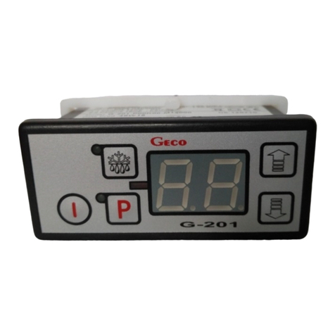
Geco G-403-P04 Operating instructions

P.P.U.H. „Geco” spółka z o.o.
30-134 Kraków ul. Zarzecze 112 A
tel. 012 6369811, 6361290
fax. 012 6362002
SERVICE & OPERATING INSTRUCTIONS
FOR AUTONOMOUS CONTROL UNIT
G-403-P04
TO CONTROL SYSTEMS
WITH SOLAR COLLECTORS
version 02
Please read these instructions very carefully before connecting and starting any of our
equipment. If in doubt, please contact our company between 8:00 a.m. - 4:00 p.m.
Note!!! The last updating of the manual is marked at the bottom of each of the following pages.
Please always use the latest version of the manual which you may obtain free of charge by mail
upon request.

PPUH „GECO” Sp. z o.o. 2ND EDITION FROM 2004-09-20

CONTENTS:
1. GENERAL CHARACTERISTICS. .......................................................................................4
2. TECHNICAL DATA ...............................................................................................................4
3. ELECTRIC INSTALLATION AND THE RULES OF CONNECTION...........................5
4. OPERATION AND THE METHOD OF CONTROL OF SBR G-403-P04 ......................5
4.1. MEASUREMENT OF TEMPERATURE........................................................................................5
4.2. DISCONNECTION OF THE FEEDING VOLTAGE .........................................................................5
5. OPERATION OF G-403-P04..................................................................................................6
5.1. ACTIVATION OF THE UNIT .....................................................................................................6
5.2. MANUAL (MASTER) OPERATION............................................................................................6
5.3. AUTOMATIC OPERATION .......................................................................................................7
5.4. TEMPERATURE VIEW.............................................................................................................7
5.5. ALARMS ...............................................................................................................................7
6. COFIGURATION OF USER PARAMETERS.....................................................................8
7. CONFIGURATION OF THE TYPE OF CONTROLLER ................................................8
8. THE CONTROLLER SYSTEM...........................................................................................10
8.1. A BASIC SYSTEM WITH ONE CONTROLLER...........................................................................10
8.2. A SYSTEM WITH ONE COLLECTOR AND OPERATION OF THE PUMP FOR THE CENTRAL HEATING
BOILER..........................................................................................................................................10
8.3. A SYSTEM WITH ONE COLLECTOR AND OPERATION OF THE PUMP FOR THE CWU................11
8.4. THE SYSTEM WITH ONE COLLECTOR AND SWIMMING POOL HEATING ..................................11
8.5. A SYSTEM WITH TWO COLLECTORS.....................................................................................12
8.6. A SYSTEM WITH ONE COLLECTOR AND A FLOOR HEATING SYSTEM .....................................13
9. TROUBLESHOOTING.........................................................................................................16

OPERATING MANUAL G-403-P04 PAGE 4
PPUH „GECO” Sp. z o.o. 2ND EDITION from 2004-09-20
1. GENERAL CHARACTERISTICS.
An autonomous control unit G-403-P04 is used to control pump operation and to stabilise
temperature in systems with solar collectors.
The G-403-P04 controller is a convenient, modern and easy to operate unit. It was made using a
microprocessor technology with automatic surface installation.
Depending on the method of installation the two-part casing allows to install the control panel
operated at safe voltage practically at any place without the necessity to mount feeding cables far
away from the controlled units.
The G-403-P04 controller is provided with:
• Three temperature sensors:
1. to measure the temperature of the solar collector,
2. to measure the temperature of the isothermal tank,
3. to measure additional temperature depending on the configuration.
It has also outlets which allow to connect units which are operated at voltage 230 V directly,
including: the PK main collector pump, an additional pump (PKT,PC,PK2) or a three-way valve
(ZT,ZP)
Adjustable parameters can be set in current operation conditions and in accordance with the
type of installation. The controller is provided with a system which protects it against the effects of
blackouts and various types of disturbances.
The controller does not require any special maintenance, the keyboard is made from special
foil which is resistant to high temperature and most chemicals. Cleaning of the keyboard with sharp
objects is not allowed; cleaning of the face of the keyboard with a wet cloth from time to time will be
sufficient.
In summer the controller should remain connected to mains, nevertheless, it should be
disconnected from mains during storms.
2. TECHNICAL DATA
operating voltage 230V +10% -15%
temperature from +5°C to +40°C
humidity from 20% to 80% RH
protection degree IP65 from the front of the control panel
CAUTION!!!
On every casing is a sticker with:
- the serial number
- a description of outlets and their load-carrying capacity
- SBR type
Total current drawn by the unit can not exceed 10A!!!
ª

OPERATING MANUAL G-403-P04 PAGE 5
PPUH „GECO” Sp. z o.o. 2ND EDITION from 2004-09-20
3. ELECTRIC INSTALLATION AND THE RULES OF
CONNECTION
1. The room in which the controller is connected should be provided with electric circuit
230V/50Hz in accordance with effective regulations.
2. The electric circuit (regardless of its type) should be ended with a plug-in socket provided
with a protective contact. Use of a socket without a protective clamp may cause an electric
shock!!!
3. The controller should be connected to a separate electric line protected with a 2-4A quick-
break fuse and an anitishock circuit-breaker with maximal activating current 30 mA.
Do not connect any other equipment to this circuit!!!
4. The clamping couplings have a permanent 16 A load certificate!!! They have a fine thread
and special plates which prevent wire cutting, therefore, light tightening of a wire results a in
a maximally good contact and use a bigger force may cause a damage of the thread.
5. Electric cables have to be well-fastened along their whole length and can not touch pipes with
glycol, the tank or pumps.
6. When the unit is connected to mains, live current can be in cables regardless whether the
button is on or off, therefore ALL REPAIRS must be done when power is
disconnected on the fuse!!!
Caution!!!
Additional equipment may be connected to the G-403-P04 controller only
by a person authorised to do electric installation works.
4. OPERATION AND THE METHOD OF CONTROL OF SBR
G-403-P04
4.1. Measurement of temperature
The controller measures temperature within the range from 0oC to 100oC. It is displayed with
a delay of 1 second. If there is a breakdown of temperature sensor or the measured temperature is out
of the range defined above (unless the unit is waiting for 60 s for stabilisation of voltage after its
disconnection) the controller informs of a breakdown of the sensor which causes that all connected
units are switched off (i.e.. the ventilator, the feeder and the pump), the unit is switched into manual
operation mode and the sign AL1 is displayed on the display if there is a breakdown of the T1
temperature sensor, AL2 is displayed on the display if there is a breakdown of the T1 temperature
sensor and AL3 is displayed on the display if there is a breakdown of the T3 temperature sensor.
Temperature of exactly 100o C will cause a display of the sign 00o.
4.2. Disconnection of the feeding voltage
After disconnection of the feeding voltage the controller begins its operation depending on
the mode in which it was set before the disconnection. The controller waits for 1 minute for
stabilisation of the electric current and returns to operation with parameter values which were
programmed before.

OPERATING MANUAL G-403-P04 PAGE 6
PPUH „GECO” Sp. z o.o. 2ND EDITION from 2004-09-20
5. OPERATION OF G-403-P04
5.1. Activation of the unit
1. Connect the unit to mains (put the plug in a socket).
First, four dots will appear on the display; then a factory program version will be seen, four
dots followed by four horizontal dashes (----) which signal that the unit is in a stand-by
position. All functions, in particular all control units connected to the controller which control
operation of the controller system, are switched off. In this position the unit does not react to
pressing of any buttons except from the button .
2. Switch on the controller using the button .
3. When the button has been pressed, the controller begins to control pump operation
automatically and reads the latest parameters programmed by the user (see item 6).
The display shows water temperature measured by the T2 sensor in the isothermal tank.
5.2. Manual (master) operation
In the automatic operation mode the user may connect the pump engine manually regardless
of the current temperature and set parameters:
1. PK collector pump:
When the button is pressed, the collector pump connected to the controller is switched
on and the upper indicator on the button is switched on permanently. When the button is
pressed again, forced operation of the pump ends and the controller controls it depending on
whether temperature conditions of its operation are met or not. If the pump is switched on
automatically, the indicator on the button flashes.
2. An additional pump (PKT,PC,PK2) or a three-way valve (ZT,ZP):
When the button is pressed, the collector pump connected to the controller is switched
on and the upper indicator on the button is switched on permanently. When the button is
pressed again, forced operation of the pump ends and the controller controls it depending on
whether temperature conditions of its operation are met or not. If the pump is switched on
automatically, the indicator on the button flashes.
The collector and the additional pump may be switched on and off independently of one another.
PUMP
EXTR
A
PUMP
MAIN

OPERATING MANUAL G-403-P04 PAGE 7
PPUH „GECO” Sp. z o.o. 2ND EDITION from 2004-09-20
5.3. Automatic operation
1. PK collector pump operation
A decision on switching on of the PK pump engine is made by the control on the basis of
information received from temperature sensors placed in the solar collector (T1)
and the isothermal tank (T2). If the difference of temperature of the solar collector and the
isothermal tank is a positive figure and bigger than the value set by the user in the ‘u0’
parameter (⇒ see: ‘Types of controller operation’) and the maximal temperature of the tank
‘u1’ has not been exceeded, the PK main collector pump is switched on and the solar
collector is the source of energy which is used to heat water in the tank.
2. Additional pump or a three-way valve operation
An additional pump or a valve are controlled depending on the chosen type of controller and
were described in item 8 (Types of controller operation).
When the button is pressed, the programming mode which does not influence automatic unit
operation is chosen.
During a normal (automatic) operation of the engine of a given pump, the diode on the
corresponding pump button is flashing and during its forced manual operation it is lit permanently.
5.4. Temperature view
The controller offers to the user a possibility to view the temperature in the solar collector. The
button should be pressed to do so. The button is used to check temperature which is
measured by an additional sensor (whose position depends on the programme of the controller).
5.5. Alarms
The controller differentiates three types of alarm. In every type of alarm the number of alarm is
displayed and an acoustic alarm outlet in the control panel is switched on. Only after pressing of the
button, alarm will end. Automatic operation of the unit can be restarted only after a removal
of the defect.
Types of alarms:
• AL1 → Damaged temperature sensor of the solar collector (T1)
• AL2 → Damaged temperature sensor of the isothermal tank (T2)
• AL3 → Damaged additional temperature sensor (T3): location depends on the programme
version and the type of installation
When temperature in the isothermal tank defined in the ‘u1’ parameter is exceeded (a standard
temperature is 90 0C) the engine of the PK collector pump is switched off unconditionally.

OPERATING MANUAL G-403-P04 PAGE 8
PPUH „GECO” Sp. z o.o. 2ND EDITION from 2004-09-20
6. COFIGURATION OF USER PARAMETERS
When the button is pressed, the controller is set in the programming mode which is signalled by
switching on of the indicator on the button . Programming does not influence current operation
of the controller.
Programming should be done carefully. It is advisable to put down the values of particular
parameters on a sheet of paper before the beginning of programming. Please, remember that a
mistake in programming may cause a defective operation or make correct operation of the system
impossible.
Caution!!
The meaning of parameters depends on the type of controller chosen by the installer!!! See:
‘Configuration of the type of controller’
1. Set the required value of parameters using the buttons , .
The permissible range of changes if a given parameter depends on the type of the controller
(type of installation).
2. Press the button again and the new value of a given parameter will be memorised.
The controller automatically moves to programming of the following parameter.
Notes:
• If the button is not pressed again, the changes will not be recorded.
• If during setting of the new temperature none of the buttons , , , is pressed
within 20 seconds, the new value will not be recorded and the controller will end the
programming mode.
This parameter is modified in an analogous way to the one defined in items 6.1 and 6.2.
When the button is pressed again, the unit will return to the situation before the beginning of
programming and the programming indicator will appear.
7. CONFIGURATION OF THE TYPE OF CONTROLLER
The type of the controller depends on the needs of installation in which it is to operate.
To change the configuration of the type of the controller, do as follows:
1. Switch off the controller with the button .
Four horizontal dashes will appear on the display.
ª

OPERATING MANUAL G-403-P04 PAGE 9
PPUH „GECO” Sp. z o.o. 2ND EDITION from 2004-09-20
2. Press the three buttons: ,
PUMP
, at the same time for about 3 seconds. The controller
moves to the programming mode which is signalled by switching on of an indicator on the
button and appearance of the ‘c0’ symbol followed by the value of that service
parameter.
3. The‘c0’ parameter means the choice of the type of controller (range: 1 – 6):
-‘1’: basic version with one collector (fig.1),
-‘2’: a version with one collector and operation of a pump for the central heating boiler. (fig.2),
-‘3’: a version with one collector and operation of a pump for the CWU tank (fig.3),
-‘4’: a version with one collector and the function of swimming pool heating through the ZT valve
(rys.4),
-‘5’: a version with two collectors (fig.5),
-‘6’- : a version with one collector and operation of floor heating through the ZP valve (rys.6),
4. Set the required value of the parameter using buttons .
When an arrow is being pressed for a longer time the value is automatically increased or
decreased depending on the chosen direction of changes. Values are interconnected so when
you reach the extreme value at one end it goes to the extreme value on the other end.
5. Press again and the new value of the parameter will be recorded.
At the same time the controller turns to reset and then to the stand-by function and the
programming indicator on the button is switched off.
6. Switch the controller on with the button .
The controller will restart its operation according to the newly recorded programme.
When the button is pressed at any moment, the controller will be switched off without
recording the modified parameter in its memory and the control indicator will be switched off.
Notes on programming of SBR:
1. THE PRODUCER IS OBLIGED TO INTRODUCE NEW PARAMETERS WHICH
ARE NECESSARY FOR NORMAL OPERATION OF THE UNIT!
2. When the unit is programmed and started up its operation and correctness of the setting of
user parameters should be checked.

OPERATING MANUAL G-403-P04 PAGE 10
PPUH „GECO” Sp. z o.o. 2ND EDITION from 2004-09-20
8. THE CONTROLLER SYSTEM
8.1. A basic system with one controller
Fig.1
Parameters available to the user
‘u0’ – (range 2-30 oC) : temperature difference which controls work of the main collector pump
‘u1’ – (range 10-90 oC): maximal temperature of the isothermal tank above which the collector pump
will be switched off
In this system the collector pump is operated in accordance with the description in item 5.3 and the
additional pump is not used. If the T3 sensor is not installed, the view of its temperature is blocked
and the AL3 alarm from that sensor is not signalled.
8.2. A system with one collector and operation of the pump for the central heating boiler.
Fig.2
Parameters available to the user
‘u0’ – (range 2-30 oC): temperature difference which controls work of the main collector pump
‘u1’ – (range 10-90 oC): maximal temperature of the isothermal tank above which the collector pump
will be switched off
‘u2’ - (range 10-90 oC): the temperature below which the PKT boiler pump will be switched on
In this system the collector pump functions in accordance with the description in item 5.3 and the
PKT boiler pump is an additional pump. It will be connected if the sensor temperature T3 is lower
than the temperature set by the user in the parameter ‘u2’.
T
collect
feed
T3
*
T
PK
T
collec
feed
T3
T
PK
PK
to boiler.

OPERATING MANUAL G-403-P04 PAGE 11
PPUH „GECO” Sp. z o.o. 2ND EDITION from 2004-09-20
8.3. A system with one collector and operation of the pump for the CWU
Fig. 3
Parameters available to the user
‘u0’ – (range 2-30 oC): temperature difference which controls work of the main collector pump
‘u1’ – (range 10-90 oC): maximal temperature of the isothermal tank above which the collector pump
will be switched off
‘u2’ – (range 10-90 oC): temperature of CWU tank above which the PC pump is switched off
‘u3’ – (range 2-30 oC): temperature difference which controls operation of the PC pump for the
CWU tank
In this system the collector pump functions in accordance with the description in item 5.3 and the PC
pump for the CWU tank is an additional pump. It is switched on if the temperature of the T3 sensor
is lower than the temperature set by the user in the parameter ‘u2’ and the difference of temperature
between the isothermal tank (T2) and the CWU tank (T3) is a positive figure, bigger than the vale set
by the user as the parameter ‘u3’.
8.4. The system with one collector and swimming pool heating
Parameters available to the user
‘u0’ : (range 2-30 oC): temperature difference which controls work of the main collector pump
‘u1’: (range 10-90 oC): maximal temperature of the isothermal tank above which the collector pump
will be switched off
‘u2’ - (range 10-90 oC): maximal temperature of the heat exchanger for the swimming pool above
which the collector pump (and the ZT valve) will be switched off
‘u3’ – (range 2-30 oC): temperature difference which controls operation of the ZT tree-way valve
‘u4’ – (range 0-10 min): duration of the break in operation of PK main pump in order to test
temperatures in relation to reheating of water in the isothermal tank (when ‘u4’=0 no test is
done)
T
collect
T
PK
P
C
T3
feed

OPERATING MANUAL G-403-P04 PAGE 12
PPUH „GECO” Sp. z o.o. 2ND EDITION from 2004-09-20
Fig. 4
In this system the collector pump functions in accordance with the description in item 5.3 and the ZT
three-way valve is an additional unit. It will be opened (heat pumping to the swimming pool) and the
PK main pump will be switched on when: - the maximal temperature of the isothermal tank set by
the user in ‘u1’parameter is exceeded and temperature difference between the collector (T1) and the
swimming pool (T3) is a positive figure and is bigger than the value set by the user in the
‘u3’parameter and the maximal temperature in the tank of swimming pool heat exchanger (T3) set
by the user in the ‘u2’ parameter has not been exceeded or
- temperature difference between the solar collector (T1) and the isothermal tank (T 2) is lower than
the value set by the user in the ‘u0’ parameter and temperature difference between the collector (T 1)
and the swimming pool (T 3) is a positive figure, bigger from the value set by the user in the ‘u3’
parameter and the maximal temperature in the tank of the swimming pool heat exchanger (T 3) set
by the user in the ‘u2’ parameter has not been exceeded.
When the heat exchanger of the swimming pool is heated, operation of the PK main pump will
be interrupted every 60 minutes to test temperature in relation to the condition of water
heating in the isothermal tank (switching of the ZT valve)! Time of the interruption is set in
user parameter ‘u4’ (where 0 means no interruptions if no testing of this condition is done).
8.5. A system with two collectors
Fig. 5
T
collect
feed
T3
T
PK
PK
heat
exchan
g
e
r
T
collect
PK
ZT
T3
feed
T
to swimming
p
ool

OPERATING MANUAL G-403-P04 PAGE 13
PPUH „GECO” Sp. z o.o. 2ND EDITION from 2004-09-20
Parameters available to the user
‘u0’: (scope 2-30 oC): temperature difference which controls operation of collector pumps
‘u1’: (scope 10-90 oC): maximal temperature of the isothermal tank above which collector pumps are
switched off
In this system the collector pump functions in accordance with the description in item 5.3 and the
PK2 collector pump is an additional pump. It is switched on if temperature difference between the
second solar collector (T3) and the isothermal tank (T2) is a positive figure and is bigger than the
value chosen by the user in the ‘u0’ parameter and the maximal temperature of the isothermal tank
defined buy the user in the ‘u1’ parameter is not exceeded.
8.6. A system with one collector and a floor heating system
Fig. 6
Parameters available to the user
‘u0’: (range 2-15 oC) temperature difference which controls work of the main collector pump
‘u1’: (range 10-90 oC) maximal temperature of the isothermal tank above which the collector pump
will be switched off
‘u2’ - (range 10-90 oC) maximal temperature of the floor heating above which the ZP valve will be
shut off
‘u3’ – (range 2-15 oC) temperature difference which controls operation of the ZT tree-way valve
In this system the collector pump functions in accordance with the description in item 5.3 and the ZP
three-way valve is an additional unit. It is opened when temperature difference between the
isothermal tank (T2) and floor heating (T3) is a positive figure and is higher than the value defined
by the user in the ‘u3’ parameter and the maximal temperature of floor heating (T3) set by the user
in the ‘u2’ parameter has not been exceeded.
ZP
T3
T
Cwu
T
PK
feed (cold water)
floor
heating
cwu central
heat. boiler

OPERATING MANUAL G-403-P04 PAGE 14
PPUH „GECO” Sp. z o.o. 2ND EDITION from 2004-09-20
PRZEDSIĘBIORSTWO
PRODUKCYJNO-USŁUGOWO-HANDLOWE
Spółka z o. o.
ul. Zarzecze 112 A, 30-134 KRAKÓW POLAND
tel.+48(12)6369811,6361290
fax.+48(12)6362002
e-mail: geco@geco.pl
http://www ge co. pl
Complaint slip no. 2
for a temperature controller
type G-403-P04
I. CONTROLLER DATA:
Controller type: .........................................................................
Production data: .........................................................................
Module series number: .........................................................................
Panel series number: .........................................................................
II. DATA OF THE COLLECTOR:
collector producer: .........................................................................
collector type (capacity): .........................................................................
PRZEDSIĘBIORSTWO
PRODUKCYJNO-USŁUGOWO-HANDLOWE
Spółka z o. o.
ul. Zarzecze 112 A, 30-134 KRAKÓW POLAND
tel.+48(12)6369811,6361290
fax.+48(12)6362002
e-mail: geco@geco.pl
http://www ge co. pl
Complaint slip no. 1
for a temperature controller
type G-403-P04
I. DATA OF THE CONTROLLER:
controller type: .........................................................................
production date: .........................................................................
module series number: .........................................................................
panel series number: .........................................................................
II. DATA OF THE COLLECTOR:
collector producer: .........................................................................
collector type (capacity): .........................................................................

OPERATING MANUAL G-403-P04 PAGE 15
PPUH „GECO” Sp. z o.o. 2ND EDITION from 2004-09-20
SBR DAMAGE DETAILS:
.................................................................................................................................................................
.................................................................................................................................................................
.................................................................................................................................................................
.................................................................................................................................................................
.................................................................................................................................................................
.................................................................................................................................................................
.................................................................................................................................................................
.................................................................................................................................................................
.................................................................................................................................................................
.................................................................................................................................................................
.................................................................................................................................................................
.................................................................................................................................................................
.................................................
Date and place of repairs
requirement reporting
..............................................
Serviceman signature
and servicing station seal

OPERATING MANUAL G-403-P04 PAGE 16
PPUH „GECO” Sp. z o.o. 2ND EDITION from 2004-09-20
9. TROUBLESHOOTING
defect symptoms check
1. The display is not lit
although the controller is
connected to mains
Check:
• whether voltage 230V is present on feeding terminals L and N
• whether the connection of the performing module with the control panel
is correct
• pull out and put back the sockets of the band
• connect another band
2. The pomp of the collector
is not switched on although
a green diode which signals
it is on
check:
• whether voltage 230V is present on feeding terminals L as described on
the upper wall of the performing module
• whether the pump is not broken
• whether the connection of the performing module with the control panel
is correct
• connect another band
3. The additional pump is not
switched on although a
green diode which signals it
is on
Check:
• whether voltage 230V is present on feeding terminals L as described on
the upper wall of the performing module
• whether the pump is not broken
• whether the connection of the performing module with the control panel
is correct
• connect another band
4. Wrong temperature
indication
Check:
• Connection of the sensor to the coupling
• whether the sensor is fixed correctly
• condition of sensor cable; the cable may not have any damages
• check in detail the outer surface of the shell of the sensor, i.e. whether it
has not been damaged mechanically
• connect another band
5. ‘abnormal’ or ‘strange’
work of the controller
Check:
• whether voltage 230V is present on feeding terminals L and N
• the condition of feeding couplings
• the condition of electric installation and the number of units connected to
one phase
• whether the control panel, the performing module or plugs of the bands
have not been wetted with water or other liquid
• whether the control panel, the performing module or plugs of the bands
are not exposed to dampness or sudden changes of temperature
• whether the connection of the performing module with the control panel
is correct
• connect another band
6. The display is flashing and
it is impossible to switch it
off
Check:
• The value of the feeding voltage
• the condition of feeding couplings
• whether feeding couplings are tightened up
• whether the connection of the performing module with the control panel
is correct
• connect another band

OPERATING MANUAL G-403-P04 PAGE 17
PPUH „GECO” Sp. z o.o. 2ND EDITION from 2004-09-20
Declaration of Conformity CE
We,
P.P.U.H. Geco sp. z o.o.
Ul. Zarzecze 112A
30-134 Kraków
declare with full responsibility that the product:
controller G-406-P…
conforms with provisions of the following directives:
73/23/EEC, 93/68/EEC
89/336/EEC, 92/31/EEC, 93/68/EEC
and with the following harmonized standards:
PN-EN 60335-1:2002
PN-EN 61000-6-1:2002, PN-EN 61000-6-3:2002
PN-EN 60730-1:2002, PN-EN 60730-2-1:2002, PN-EN 60730-2-9:2004,
Piotr Gębik, MSc, Eng.
Company President
Kraków, 30.06.2004

OPERATING MANUAL G-403-P04 PAGE 18
PPUH „GECO” Sp. z o.o. 2ND EDITION from 2004-09-20


P.P.U.H. „Geco” spółka z o.o.
ul. Zarzecze 112 A
30-134 Kraków POLAND
tel. 012 6369811, 6361290
fax. 012 6362002
Table of contents
Other Geco Control Unit manuals