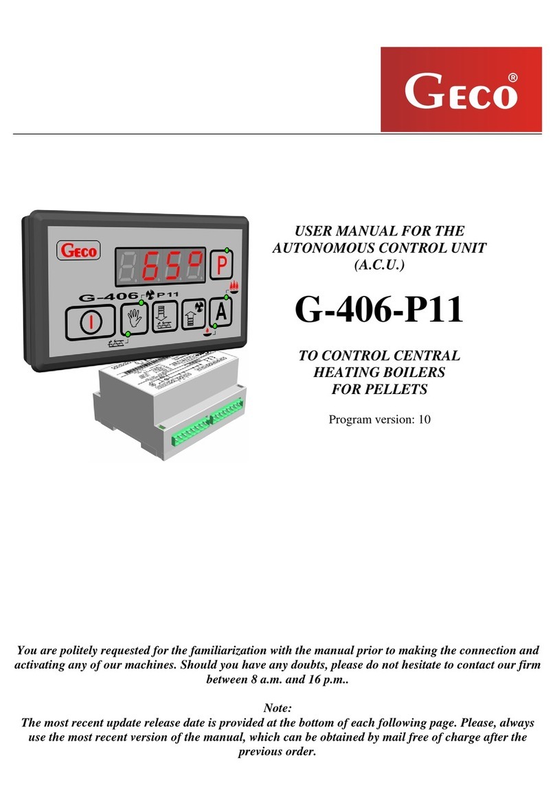
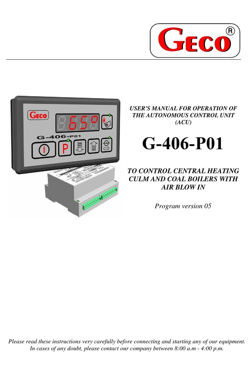
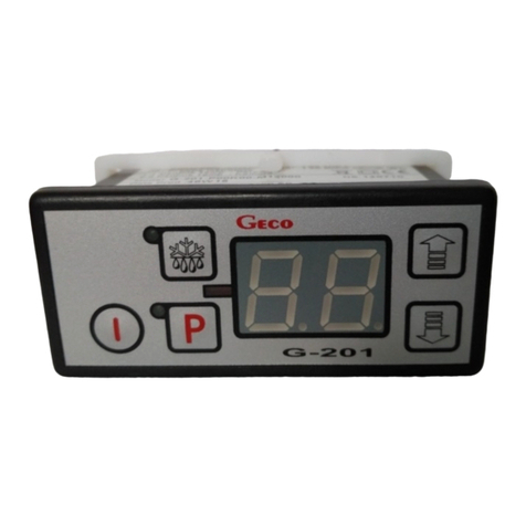
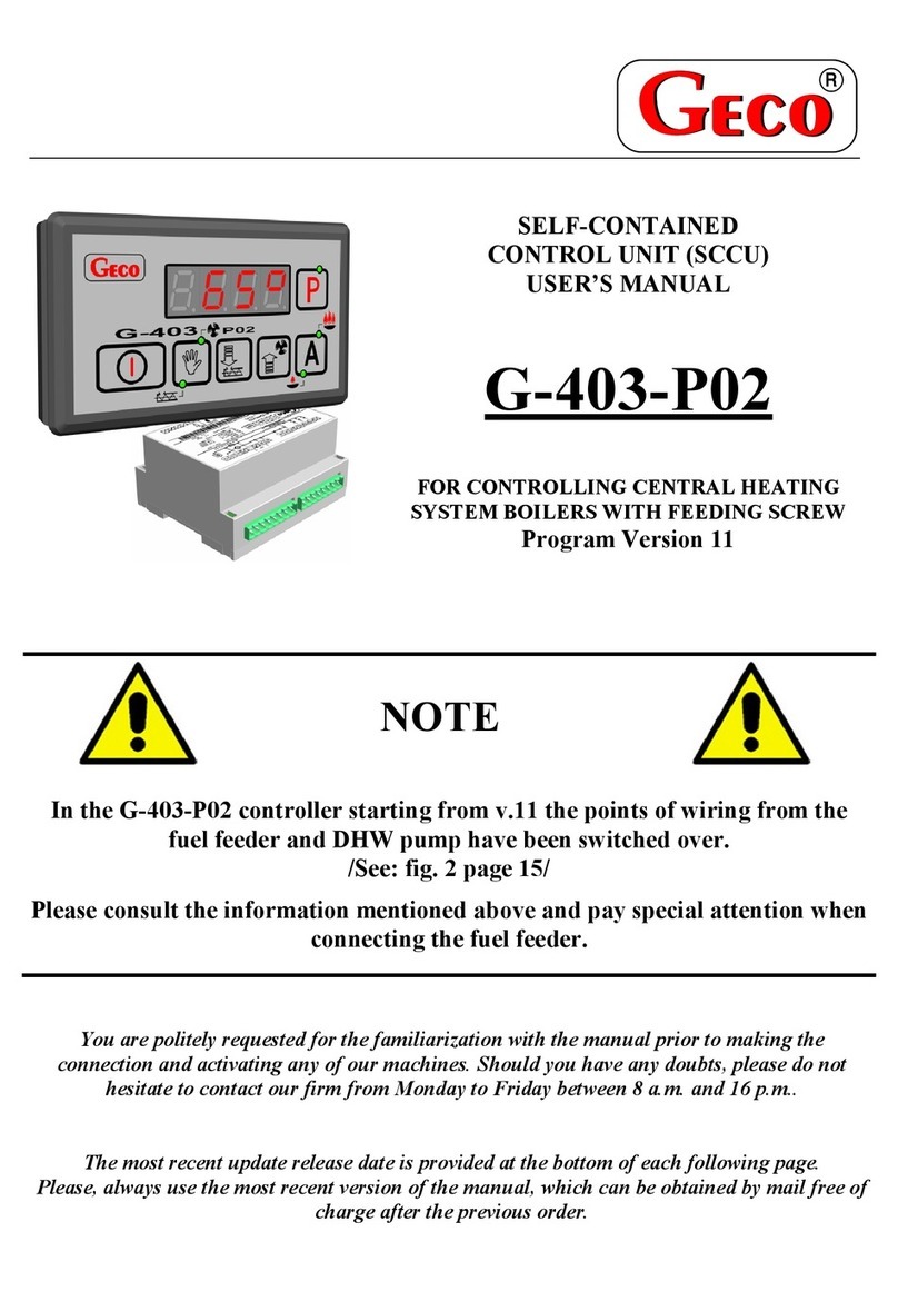
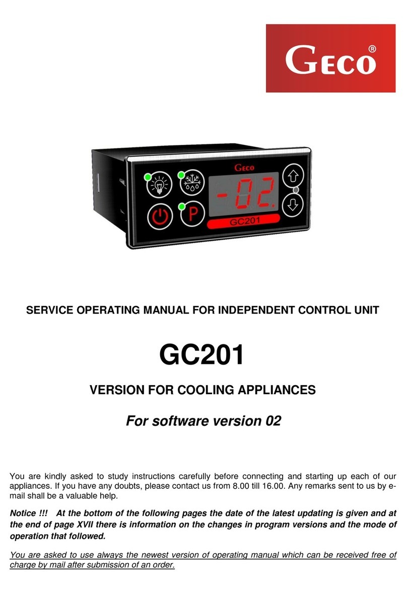
Geco GHC201.07 Parts list manual

SERVICE OPERATING MANUAL FOR INDEPENDENT CONTROL UNIT
GHC201.07
GHC201.08
Version for cooling and heating appliances
For software version 03A
You are kindly asked to study instructions carefully before connecting and starting up each of our appliances. If
you have any doubts, please contact us from 8.00 till 16.00. Any remarks sent to us by e-mail shall be a
valuable help.

strona 2 INSTRUKCJA SERWISOWA GHC201.07 i GHC201.08
PPUH „GECO” Sp. z o.o. Wydanie I OD DNIA 2018-02-22
Table of contents:
I. GENERAL CHARACTERISTICS ............................................................................ 3
II. METHOD OF MARKING AND TECHNICAL DATA ................................................ 3
III. HOW TO ORDER............................................................................................... 4
IV. INSTALLATION AND CONNECTION OF GHC201.08 ......................................... 4
V. INSTALLATION OF SENSORS............................................................................. 5
VI. OPERATION METHOD ................................................................................... 5
A–GENERAL INFORMATION......................................................................................... 5
B–FUNCTIONAL DESCRIPTION OF CONTROL BLOCKS: ......................................................... 6
C–PROGRAMMING RELAYS FUNCTIONS .......................................................................... 9
D–PROGRAMMING OF USER PARAMETERS...................................................................... 9
E–ALARMS AND EMERGENCY OPERATION ..................................................................... 10
F–TEMPERATURE DISPLAY......................................................................................... 11
VII. PPROGRAMMING OF SYSTEM PARAMETERS .............................................. 12
VIII. PROBLEMS AND THEIR REMOVAL ............................................................... 13
IX. RETURNS FOR REPAIR .................................................................................... 14
X. METHOD OF CONNECTION DEVICES TO THE CONTROLLER............................. 15
XI. INFORMATION ABOUT MARKING AND COLLECTION OF USED ELECTRICAL AND
ELECTRONIC EQUIPMENT .................................................................................... 17

INSTRUKCJA SERWISOWA GHC201.07 i GHC201.08 strona 3
PPUH „GECO” Sp. z o.o. Wydanie I OD DNIA 2018-02-22
I. GENERAL CHARACTERISTICS
WARNING!!! Since this manual applies to two controllers with the same principle of operation, but difference
in the number of relay outputs, in the following part we will refer to the name of only a more complex
regulator GHC201.08.
Independent Control Unit called further GHC201 is a modern, comfortable and easy to operate appliance.
It was produced using microprocessor technology and automatic surface assembly.
GHC201.08 has two thermostats. Each of them can used for heating or cooling or one can be used as a
universal heating-cooling thermostat.
GHC201 has the ability to select work with one or two temperature sensors and has two relay outputs
enabling direct connection for devices operating at 230V with load capacity in accordance with Table 1.
In the GHC201.08 controller there is possibility to define function of every output. Thanks to this feature the
device is very easy to suit depending on its application. The controller can be used for instance: there, where one
need to turn one heater on, as well as there, where one need to control heating and cooling independently or where
one need to control only cooling.
The controller is equipped with sound signaling as standard, which activates when any button is pressed on
the keypad and when an alarm occurs.
In order to provide the user with the comfort of using the controller, capacitive (touch) buttons were used in
the keyboard.
This thermostat does not require special maintenance; the keyboard was made from a special type of foil
resistant to high temperature and most chemicals. It is not permitted to clean it with sharp objects. It is sufficient
to clean the front plate with a wet cloth from time to time.
II. METHOD OF MARKING AND TECHNICAL DATA
Model: GHC201.0X
0X –number indicating the version of the controller
07 –one-relay version of controller
08 –two-relay version of controller
Operating Voltage
230V AC +10% -15%
Enviroinment Temperature
od +5oC do +40oC
Humidity
od 20% do 80% RH
Protection Level
IP65 Front side of control panel
Sensors type
NTC 2,2kΩ - range: from -400C to +600C

strona 4 INSTRUKCJA SERWISOWA GHC201.07 i GHC201.08
PPUH „GECO” Sp. z o.o. Wydanie I OD DNIA 2018-02-22
Tabela 1: Marking of transformers and carrying capacity of outlets
Wyjście
Obciążalność
P1 –Uniwersal
4A
750W
P2 –Uniwersal
2A
450W
Uwaga !!!
Total power consumed at once by appliances must not exceed 10A !!!
III. HOW TO ORDER
In the order you have to give the full name of the controller in accordance with the marking defined in ‘II’
For example.:
GHC201.07 one-relay thermostat
GHC201.08 two-relay thermostat
Additionally you need to give a number and a length of temperature sensors . Standard length of sensors:
2,5m and 3,0m.
IV. INSTALLATION AND CONNECTION OF GHC201.08
1. Cut a hole with dimensions 28x70 mm in the appliance in the place marked accordingly.
2. All metal elements through which GHC201 or its cables are put should be filed or protected otherwise. I is
not permitted to fix GHC201 in a way which allows direct contact with water (e.g. condensing water on
the lower cover of the display), touching of evaporator outlet pipe etc. and causes considerable changes
of its temperature in comparison with air temperature (e.g. fixing in direct vicinity of the compressor and
its accessories, cooling and heated elements).
3. When GHC201.08 is fixed, power cables should be connected in accordance with the description on the
casing. In the case of versions GHC201.07 with one relay, the output of the other relay will be unused - it
will be marked with a cross on the label with the description - no wires should be connected to these
outputs !!!
4. Connectors have certification for permanent load 16A !!! They are provided with fine thread and special
plates preventing cutting of cables, therefore, when lightly screwed together they will have maximally
good contact and if more force is applied, it may damage the thread. In result the socket may be melted
and there might be a short circuit!!!
5. The whole unnecessary length of cables is shortened by cutting or winding and clipping together by
special plastic bands. Cable have to be well-fastened along their whole length and may not touch the
compressor and its accessories.

INSTRUKCJA SERWISOWA GHC201.07 i GHC201.08 strona 5
PPUH „GECO” Sp. z o.o. Wydanie I OD DNIA 2018-02-22
6. If there are heaters, their voltage has to be chosen in such a way that if there is a breakdown of
GC201.08 or of an external contactor and they are switched off permanently, there will be no possibility
of fire or destruction of the appliance. If high power heaters are used, safety thermostat must be used
on the evaporator unconditionally. This thermostat should operate on a different basis, e.g. a
mechanical thermostat.
REPAIR OR CONNECTIONS CAN BE PERFORMED ONLY WITH DISCONNECTED POWER !!!
V. INSTALLATION OF SENSORS
1. For every type of the cooling unit the place of fixing of chamber and evaporator sensor and setting of system
parameters GHC201 should be chosen through experimentation.
1. Sensor cables can be shortened or lengthened in any way according to the following rules:
-Cable sensor should not be cut at a distance below 0.5 m from the shell
-It is not recommended to lengthen sensor cable above 20 m.
-SENSOR CABLES CAN BE CONNECTED TO SENSOR CLAMPS IN THE OPERATING UNIT IN ANY WAY!!!
(similarly to the method of plugging of the plug in the socket ~230V)
-cable OMY 2x0.5 mm is recommended for cable lengthening,
-if cables are lengthened their connection should be done very carefully, every pair of veins should be
soldered and heat-shrinking sheaths should be put on them. Then the place of connection should be
filled with water-resistant silicone and one more heat-shrinking sheath should be put on..
-endings of cable connected to the independent control unit should be tinned.
VI. OPERATION METHOD
A –General Information
1. When the unit is connected to mains a start procedure takes place after which a short signal of buzzer is
given and three dots appear for a second on the display, then version of controller’s program, and three dots
one more time. At that time none of controlled units is switched on. During a test procedure it is better not
to touch any of sensors because they are calibrated.
Touching buttons while test procedure is taken may result in incorrect work of keyboard! In this case you
need to disconnect and connect controlled again to power supply.
2. When a test procedure is finished display shows 3 horizontal dashes informing that controller is operated
under voltage - if the device has not been turned on before !!! Turning GHC201 on and off take place when
you press and hold button for 5 seconds. When you hold down the button, a rising sound signal is
generated. Temperature from one os sensors (check ‘r7’ parameter) is displayed.

strona 6 INSTRUKCJA SERWISOWA GHC201.07 i GHC201.08
PPUH „GECO” Sp. z o.o. Wydanie I OD DNIA 2018-02-22
Controller signals pressing each button by buzzer signal. When controller is switched of the buzzes signals
only pressing button.
3. Switching on the P1 relay is indicated by a dot on the z display marked with reference number 1. Switching on
the relay P2 is signaled by lighting the dot on the display with reference number 2.
B –Functional description of control blocks:
Block 1 controls the devices based on measurements from the sensor 1. There are two types of regulation
selected using the 'r5' parameter.
If the parameter 'r5' has been set to 1, the controller controls the heating and cooling of block 1 separately.
The adjustment method is shown in Figure 1:
Fig 1. Principle of controlling the relays by the control block in "cooling and heating given separately" - thick line
means switching the relay on
‘Heating set temperature’ is set by the user as parameter ‘u1’, in range of ‘d0’ - ‘d1-1’ (factory setting u1=2).
‘Heating activation temperature’ is calculated as ‘u1’ – value of heating hysteresis ‘d2’.
‘Heating off temperature’ is calculated as ‘u1’ + value of heating hysteresis ‘d2’.
temperature
Cooling set temperature
Heating set temperature
Cooling hysteresis
Heating hysteresis
Cooling activation temperature
Cooling off temperature
Heating off temperature
Heating activation temperature
Parameter ‘d8’
Parameter ‘d8’
Temperature of overcooling alarm activation
Temperature of overheating alarm activation
time
cooling
heating
overheating
overcooling
alarm

INSTRUKCJA SERWISOWA GHC201.07 i GHC201.08 strona 7
PPUH „GECO” Sp. z o.o. Wydanie I OD DNIA 2018-02-22
‘Cooling set temperature’ is set by the user as parameter ‘u2’ in range of ‘u1+1’- ‘d1’ (factory setting u2=4).
‘Cooling activation temperature’ is calculated as ‘u2’+ value of cooling hysteresis ‘d3’.
‘Cooling off temperature’ is calculated as ‘u2’ - value of cooling hysteresis ‘d3’.
If the parameter 'r5' has been set to 2, the controller controls heating and cooling (in the same range) of
block 1. The adjustment method is shown in figure 2:
Fig 2. Principle of controlling the relays by the control block in "cooling and heating in the same range" - thick line
means switching the relay on
‘Set temperature’is given by user as ‘u1’parameter, in range of ‘d0’ - ‘d1-1’ (factory setting: u1=2).
‘Heating activation temperature / cooling off temp.’is calculated as‘u1’ –value of hysteresis ‘d2’.
‘Heating off temperature / cooling activation temp.’ is calculated as ‘u1’ + value of hysteresis ‘d2’.
The cooling relay is switched on when the following conditions are met:
• 'temperature 1' is equal to or greater than the 'cooling activation temperature'.
• after the time 'c2' has elapsed since the last cooling shutdown.
• The heating relay is turned off
• after the time 'c2' has elapsed since the power was turned on. *
• after the time 'c6' has elapsed - if the 'c5' parameter has been protected - the maximum working time*
*After turning on the controller with button, cooling activation time is reduced to:
- 5 seconds, while ‘c2’ is different than zero,
- 0, when ‘c2’ is zero,
It is made to enable service technicians to quickly switch on the cooling.
temperature
Set temperature
Hysteresis
Heating off temperature / cooling activation temp.
Heating activation temperature / cooling off temp.
Parameter ‘d8’
Parameter ‘d8’
Temperature of overcooling alarm activation
Temperature of overheating alarm activation
time
cooling
heating
overheating
overcooling
alarm

strona 8 INSTRUKCJA SERWISOWA GHC201.07 i GHC201.08
PPUH „GECO” Sp. z o.o. Wydanie I OD DNIA 2018-02-22
The heating relay is switched on when the following conditions are met:
‘temperature 1’ is equal or smaller than the ‘heating activation temperature’.
Cooling relay is switched off.
Block 2 is the same as block 1 but it can be turned off (‘r6’=0).
Analogous to the description of block 1, if 'r6' = 1 (cooling and heating controlled separately):
The adjustment method is shown in figure 1.
‘Heating set temperature’ is set by the user by ‘u3’ parameter, in range of
‘d0’ - ‘d1-1’ (factory setting: u3=2).
‘Heating activation temperature’ is calculated as ‘u3’ – value of heating hysteresis ‘d5’.
‘Heating off temperature’ is calculated as ‘u3’ + value of heating hysteresis grzania ‘d5’.
‘Cooling activation temperature’ is set by the user by ‘u4’ parameter, in range of ‘u3+1’- ‘d1’ (factory setting:
u4=4).
‘Cooling activation temperature’ is calculated as ‘u4’ + value of cooling hysteresis ‘d6’.
‘Cooling off temperature’ is calculated as ‘u4’ - value of cooling hysteresis ‘d6’.
If 'r6' = 2 (cooling and heating control in the same range):
The adjustment method is shown in figure 2.
‘Set temperature’ is set by the user as a ‘u3’ parameter, in range of ‘d0’ - ‘d1-1’ (factory setting: u3=2).
‘Heating activation temperature / cooling off temp.’is calculated as ‘u3’ – value of hysteresis ‘d5’.
‘Heating off temperature / cooling activation temp.’ is calculated as ‘u3’ + value of hysteresis ‘d5’.
The cooling relay is switched on when the following conditions are met:
'temperature 2' is equal to or greater than the 'heating activation temperature'.
after the time 'c2' has elapsed since the last cooling shutdown.
The heating relay is turned off
after the time 'c2' has elapsed since the power was turned on. *
after the time 'c6' has elapsed - if the 'c5' parameter has been protected - the maximum working time*
*After turning on the controller with button, cooling activation time is reduced to:
- 5 seconds, while ‘c2’ is different than zero,
- 0, when ‘c2’ is zero,
It is made to enable service technicians to quickly switch on the cooling.
The heating relay is switched on when the following conditions are met:
‘temperature 2’ is equal or smaller than the ‘heating activation temperature’.
Cooling relay is switched off.

INSTRUKCJA SERWISOWA GHC201.07 i GHC201.08 strona 9
PPUH „GECO” Sp. z o.o. Wydanie I OD DNIA 2018-02-22
C –Programming relays functions
1. Controller has two relays, each of them can be configured independently.
2. Each relay has own parameter which decide about its application.
3. It is not allowed to assign the same function for two relays because only one is supported at the
same time.
4. Relay P1 was assigned with r2 parameter.
5. Relay P2 was assigned with r1 parameter.
6. Relays can be assigned with following functions:
0- Unused
1- Block 1 cooling
2- Block 1 heating
3- Overheating alarm for block 1
4- Overcooling alarm for block 1
5- Block alarm (any block)
6- Block 2 cooling
7- Block 2 heating
8- Overheating alarm for block 2
9- Overcooling alarm for block 2
10- any alarm –block 2
Each relay can be controlled by block 1 or block 2.
7. Function programming is available from the Service Parameters Programming level.
8. Relays should be (look at point 1).
9. There is a possibility not to connect any relay to block –the block serves as a thermometer then.
D –Programming of user parameters
1. To switch on parameters programming mode button has to be pressed. After that a diode
on a button is lighted, it means programming mode is active. For a second name of
parameter ‘u1’ will appear on the display and then the value of this parameter. This value could be
changed by using or buttons, in range:
U1: ‘d0’ – ‘d1 - 1’;
U2: ‘u1+ 1’ – ‘d1’;
U3: ‘d0’ – ‘d1 - 1’;
U4: ‘u3+ 1’–‘d1’;
2. By pressing button again you save the parameter ‘u1’ value and switch to programming
the next parameter.
3. Depending on the programming of parameters r5 and r6 the list of user parameters may change.
4. If ‘r5’=1 parameters ‘u1’ o ‘u2’ can be programmed; If ‘r5’=2 only parameter ‘u1’ can be
programmed.

strona 10 INSTRUKCJA SERWISOWA GHC201.07 i GHC201.08
PPUH „GECO” Sp. z o.o. Wydanie I OD DNIA 2018-02-22
5. If ‘r6’=1 parameters ‘u3’ o ‘u4’ can be programmed; If ‘r6’=2 only parameter ‘u3’ can be
programmed; If ‘r6’=0 we cannot program parameter ‘u3’ or ‘u4’
6. After the last parameter is programmed a led diode on the button is switched off.
E –Alarms and emergency operation
In case of ‘sensor 1’ failure it occurs:
Heating and cooling relays (for block 1) are controlled in time cycle (clock control)
For ‘c8’ time heating relay is switched off and cooling relay is on
For ‘c9’ time heating relay is switched on and cooling relay is off
Switching on all block 1 alarm relays
Alarm code AL1 is displayed
In case of ‘sensor 2’ failure it occurs
Heating and cooling relays (for block 2) are controlled in time cycle (clock control)
For ‘c8’ time heating relay is switched off and cooling relay is on
For ‘c9’ time heating relay is switched on and cooling relay is off
Switching on all block 2 alarm relays
Alarm code AL2 is displayed
If two sensors fail at the same time, alarms AL1 and AL2 are displayed alternately.
The controller can report temperature exceeding alarms.
If ‘temperature 1’ is higher than ‘cooling activation temperature for the block 1’ + ‘d8’ overheating
alarm relay is switched on and the block 1 alarm relay is switched on to.
If ‘temperature 1’ is lower or equal to ‘heating activation temperature for the block 1’ - ‘d8’ overcooling
alarm relay is switched on and the block 1 alarm relay is switched on.
If ‘temperature 2’ is higher than ‘cooling activation temperature for the block 2’ + ‘d8’ overheating
alarm relay is switched on and the block 2 alarm relay is switched on to.
If ‘temperature 2’ is lower or equal to ‘heating activation temperature for the block 2’ - ‘d8’ overcooling
alarm relay is switched on and the block 2 alarm relay is switched on.
Example 1:
Parameters are set: r5=1 i r6=1
entering the programming mode, u1 is displayed and next a value of this parameter
change the u1 parameter value in range of ‘d0’ – ‘d1 - 1’
memorizing u1 value, u2 is displayed and a value of this parameter

INSTRUKCJA SERWISOWA GHC201.07 i GHC201.08 strona 11
PPUH „GECO” Sp. z o.o. Wydanie I OD DNIA 2018-02-22
change the u2 parameter value in range of ‘u1 + 1’ – ‘d1’
memorizing u2 value, u3 is displayed and a value of this parameter
change the u3 parameter value in range ‘d0’ – ‘d1 - 1’
memorizing u3 value, u4 is displayed and a value of this parameter
change the u4 parameter value in range ‘u3 + 1’–‘d1’
memorizing u4 value and exiting a programming mode
Example 2:
Parameters are set: r5=2 i r6=2
entering the programming mode, u1 is displayed and next a value of this parameter
change the u1 parameter value in range of ‘d0’ – ‘d1 - 1’
memorizing u1 value, u3 is displayed and a value of this parameter
change the u3 parameter value in range ‘d0’ – ‘d1 - 1’
memorizing u3 value and exiting a programming mode
Example 3:
Parameters are set: r5=1 i r6=0
entering the programming mode, u1 is displayed and next a value of this paramete
change the u1 parameter value in range of ‘d0’ – ‘d1 - 1’
memorizing u1 value, u2 is displayed and a value of this parameter
change the u2 parameter value in range of ‘u1+1’ – ‘d1’
memorizing u2 value and exiting a programming mode
F –Temperature display
1. The controller display temperature from block 1 as a standard
2. If the ‘r6’ parameter is different than 0 and ‘r7’=1, temperature from block 2 is displayed
3. After pressing button, the second temperature which is measured is displayed ( it blinks ),
after 5 second has passed controller will automatically return to the display of dominant block
temperature

strona 12 INSTRUKCJA SERWISOWA GHC201.07 i GHC201.08
PPUH „GECO” Sp. z o.o. Wydanie I OD DNIA 2018-02-22
VII. PPROGRAMMING OF SYSTEM PARAMETERS
When the unit is switched on and correctness of its operation has been checked (factory settings are
standard settings) setting of system parameters of GHC201.08 begins.
In order to do that, the unit must be switched off with the button (three horizontal lines appear on the
screen). Then buttons and must be pressed and holded. When they are being pressed, the button
must be pressed too (short sound signal is activated). All three buttons must be pressed together for about
5 seconds. If any of the buttons is released at that time, programming will be interrupted. When this activity is
done, diode on button will flash and symbol ‘c2’ will appear on the display for 1 second. Then the latest
programmed value of the parameter will appear. Now, using buttons the new values should be set;
every longer pressing of the button will cause quick winding of possible settings. Then should be pressed to
accept the set data and start programming of a new parameter.
It is possible to change some settings only if you do not want to change a given parameter, press and
GHC201.08 will move to the next parameter.
After entering the last parameter setting and accepting it with the button , it will automatically exit the
programming mode and return to STANDBY mode (two horizontal lines on the display).
If no button is pressed within 20 seconds, the device will exit the parameter programming mode.
Notice !!!
Incorrect set of parameters settings may cause a faulty operation!!!
Table 2: Significance of parameters
Para-
metr
Opis
Min
Max
Krok
Nastawa
fabryczna
c2
Minimal time of compressor stoppage
0
15
1min
3 min
c5
Maximal time of operation of compressor
0 –no testing (this parameter is off)
0
99
1min
40 min
c6
Time of compressor stoppage after switching on of protection from
parameter ‘c5’
1
99
1min
10 min
c8
Compressor operation time / heater stoppage time if the control
sensor is damaged
1
99
1min
25 min
c9
Compressor stoppage time / heater operation time if the control
sensor is damaged
1
40
1min
5 min
d0
Minimal temperature for a client to set
-40
119
1°C
1 °C
d1
Maximal temperature for a client to set
d0+1
120
1°C
10 °C
d2
Heating hysteresis for block 1 or hysteresis when r5=2
1
10
1°C
2 °C
d3
Cooling hysteresis for block 1
1
10
1°C
2 °C

INSTRUKCJA SERWISOWA GHC201.07 i GHC201.08 strona 13
PPUH „GECO” Sp. z o.o. Wydanie I OD DNIA 2018-02-22
d4
Temperature offset for temperature sensor 1
-10
10
1°C
0°C
d5
Heating hysteresis for block 2 or hysteresis when r5=2
1
10
1°C
2 °C
d6
Cooling hysteresis for block 2
1
10
1°C
2 °C
d7
Temperature offset for temperature sensor 2
-10
10
1°C
0°C
d8
Temperature deviation out of adjustment range
0
10
1°C
3°C
r1
Settings for P2 relay:
00- not used
01- block 1 cooling
02- block 1 heating
03- overheating alarm for block 1
04- overcooling alarm for block 1
05- any alarm for block 1
06- block 2 cooling
07- block 2 heating
08- overheating alarm for block 2
09- overcooling alarm for block 2
10- any alarm for block 2
00
10
1
01
r2
Settings for P1 relay - Values as shown above in r1
00
10
1
02
r5
Type of regulating block 1 (always switched on)
01- cooling and heating given separately
02- cooling and heating in the same range
01
02
1
01
r6
Type of regulating block 2
00- not used (there is no alarm from the temperature sensor)
01- cooling and heating given separately
02- cooling and heating in the same range
00
02
1
01
r7
The dominant regulatory block (from which temperature is
displayed)
00- block 1
01- block 2
00
01
1
00
VIII. PROBLEMS AND THEIR REMOVAL
defect symptoms
check
1. Display is not lit
although GC201.08 is
connected to mains
Check:
- if there is voltage 230V on feeding clamps L and N
2. Error of temperature
indication
Check:
- connection of sensors to connectors
- the value of parameter ‘d4’
- if the sensor is fixed correctly
- the condition of the cable of the sensor: the cable cannot have any
defects
- in detail the lookout of external surface of sensor shell to see whether it
has not been damaged mechanically.
3. impossible to set
Check:

strona 14 INSTRUKCJA SERWISOWA GHC201.07 i GHC201.08
PPUH „GECO” Sp. z o.o. Wydanie I OD DNIA 2018-02-22
the required
temperature
the value of parameters ‘d0’ and ‘d1’ (d0<d1)
4. Compressor does
not switch on although
it is connected
Check:
- if there is voltage 230V on clamps P1 or P2
- value of parameters ‘r1’ or ‘r2’
5. Heater does not
switch on although it is
connected
Check:
- if there is voltage 230V on clamps P1 or P2
- value of parameters ‘r1’ or ‘r2’
6. Buzzer does not
switch on although it is
connected
Check:
- if there is voltage 230V on clamps P1 or P2
- value of parameters ‘r1’ or ‘r2’
- value of ‘d8’ parameter
7. Dots on the display
flash, no possibility to
switch it on
Check :
- the value of feeding voltage
- condition of feeding connectors
- whether feeding connectors are tightened up
8. ‘’abnormal’
‘strange’ operation of
the unit
Check:
- if there is voltage 230V on feeding clamps L and N
- condition of feeding connectors
- ‘zeroing’ of cooling unit
- condition of electric system and the number of units connected to one
phase (sticker on a case)
- weather GHC201.08 was not wetted by water or other liquid
- if GHC201.08 is not exposed to humidity or sudden changes of
temperature
9. The appliance does
not reach the set
temperature and does
not cool
Check:
- what temperature was programmed by the user
- set values of particular parameters, in particular ‘c2’, ‘c5’, ‘d0’, ‘d1’
- the method and place of fixing of the temperature sensor
- WHETHER THE UNIT STANDS IN A DRAFT OR IN SUNLIGHT!!!
- whether ventilators or air conditioning are installed on the ceiling or
nearby
IX. RETURNS FOR REPAIR
PPUH ‘GECO’ reserves the right to refuse a free repair of the unit, if
the seals are broken !!!
P.P.U.H. ‘Geco’ Sp. z o. o. is not responsible for loses and damages resulting from
provision of information on the method of making changes in the system data of
GHC201.07 or GHC201.08 by the producer or its service to the final client, incorrect or
non-professional assembly and for loses caused by defective operation of the
appliance.

INSTRUKCJA SERWISOWA GHC201.07 i GHC201.08 strona 15
PPUH „GECO” Sp. z o.o. Wydanie I OD DNIA 2018-02-22
X. METHOD OF CONNECTION DEVICES TO THE CONTROLLER
Fig. 1. Diagram of connecting devices and sensors for the GHC201.07 controller.

strona 16 INSTRUKCJA SERWISOWA GHC201.07 i GHC201.08
PPUH „GECO” Sp. z o.o. Wydanie I OD DNIA 2018-02-22
Fig 2. Diagram of connecting devices and sensors for the GHC201.08 controller.

INSTRUKCJA SERWISOWA GHC201.07 i GHC201.08 strona 17
PPUH „GECO” Sp. z o.o. Wydanie I OD DNIA 2018-02-22
XI. INFORMATION ABOUT MARKING AND COLLECTION OF USED
ELECTRICAL AND ELECTRONIC EQUIPMENT
WARNING!
The crossed-out wheelie bin symbol on your product or packaging reminds
you that all electrical and electronic products be taken to separate collection
at the end of their working life. Do not dispose of these products as
unsorted municipal waste take them for recycling. The user is responsible
for taking used device to recycling point.
.

P.P.U.H. „Geco” Sp. z o. o.
Cholerzyn 376, 32-060 Liszki
tel. 012 6369811, 6361290
fax. 012 6362002
http://www.geco.pl
This manual suits for next models
1
Table of contents
Other Geco Control Unit manuals
Popular Control Unit manuals by other brands

HID
HID Lumidigm M Series Mechanical Integration Guide

Microtips Technology
Microtips Technology DEPG0750RWU790F30 user manual

Vag
Vag TOP-STOP Operation and maintenance instructions

ABB
ABB FSE-31 user manual

Honeywell
Honeywell NetAXS user guide

Grundfos
Grundfos PLV Series Installation and operating instructions