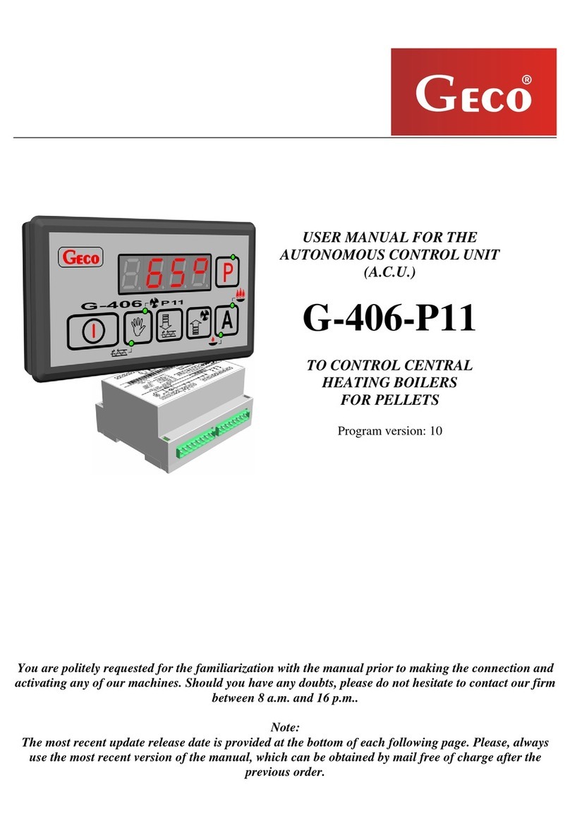
Geco G-406-P01 User manual

USER'S MANUAL FOR OPERATION OF
THE AUTONOMOUS CONTROL UNIT
(ACU)
G-406-P01
TO CONTROL CENTRAL HEATING
CULM AND COAL BOILERS WITH
AIR BLOW IN
Program version 05
Please read these instructions very carefully before connecting and starting any of our equipment.
In cases of any doubt, please contact our company between 8:00 a.m - 4:00 p.m.

CONTENTS:
1. GENERAL ...................................................................................................................................3
2. TECHNICAL DATA ...................................................................................................................3
3. ELECTRICAL SYSTEM AND CONNECTING RULES ..........................................................3
4. OPERATION AND ADJUSTMENTS OF THE G-406-P01.......................................................4
5. USING G-406-P01.......................................................................................................................5
5.1. Operating states of the unit:.................................................................................................5
5.2. Starting the unit ...................................................................................................................5
5.3. Lighting up the boiler ..........................................................................................................5
5.4. Manual and automatic control of c.h. pump........................................................................6
5.5. Viewing the stack temperature ............................................................................................6
5.6. Indication of fan operation ..................................................................................................7
5.7. Alarm states .........................................................................................................................7
5.8. Supply voltage loss..............................................................................................................8
6. Configuration of User's parameters..............................................................................................8
6.1. Preset temperature of outlet water (u0) ...............................................................................8
6.2. Preset temperature of boiler water (u1)...............................................................................9
7. USING THE D.H.W. TANK .......................................................................................................9
7.1. Installation and connection..................................................................................................9
7.2. Parameter configuration ....................................................................................................11
8. CONNECTING THE UNIT TO CONTROLLER G-406-P01:.................................................12
9. TROUBLESHOOTING .............................................................................................................15

USER'S MANUAL G-406-P01 PAGE 3
PPUH „GECO” Sp. z o.o. G-406-P01-U-v05a-w01 2005-09-20
1. GENERAL
Autonomous Control Unit (ACU) referred to hereinafter as G-406-P01 is a state-of-the-art,
convenient and easy to use system. It's design combines microprocessor-based technology and
surface assembly. The controller is made up of a keyboard with LED display connected with a
ribbon to the actuator in a plastic bus housing. Sensor/actuation unit cables are connected to the
actuator using connectors according to the description on the housing label. G-406-P01 has been
equipped with three sensors indicating the temperature of outlet water, exhaust gases in the stack
and water temperature in the boiler (option) and three outputs allowing direct hookup of C.H. pump
DHW pump and supply fan of 230V power supply with current consumption as per table 1. The
signal lamp on the module informs of the power and fuse status. G-406-P01 does not require special
maintenance. The console is made of special foil resistant to high temperatures and most chemical
agents. Do not use sharp objects for cleaning the console.
2. TECHNICAL DATA
1. Operating Voltage ⎯30V +10% -15%
2. Temperature ⎯from +5°C to +40°C
3. Humidity ⎯from 20% to 80% RH
Table 1 Output load-carrying capacity
Output designation standard version
C.H. pump 1,5A 1/3HP 250W
Additional d.h.w. pump/alarm/ 1,5A 1/3HP 250W
Fan 1,5A 1/3HP 250W
NOTE !!!
A label affixed to each housing indicates:
- serial number
- output description and output load-carrying capacity
- ACU type
3. ELECTRICAL SYSTEM AND CONNECTING RULES
1. Boiler room should be provided with 230V/50Hz electrical system in accordance with the
applicable law.
2. Electrical system (regardless of its type) should be terminated with a plug-in socket
equipped with a protective contact. Using the socket without the connected protective
terminal can result in electric shock!!!
3. The controller should be connected to a separately run feeding line protected with quick-
blow fuse 2-4A and current-differential circuit breaker (electric shock protection) with a
maximum tripping current of 20 mA. Do not connect to this line any equipment!!!
4. The applied connectors are certified for continuous load of 16A!!! They incorporate fine
thread and special lamellae, which prevent the wires from being cut, therefore only light
tightening ensures maximum good contact and the use of greater force may lead to
stripping out of the thread.
ª

USER'S MANUAL G-406-P01 PAGE 4
PPUH „GECO” Sp. z o.o. G-406-P01-U-v05a-w01 2005-09-20
5. The power cables must be firmly secured on its entire length and must not get in contact
with the water jacket or outlet to the stack.
6. After connecting the unit to the power source there can be voltage across the cables
regardless of switching on or off the unit with the button therefore ANY REPAIRS
must be done only with the power supply cut with the fuse!!!
4. OPERATION AND ADJUSTMENTS OF THE G-406-P01
1. The controller incorporates protection from:
A. Increase of temperature in the stack above the following levels:
•During lighting up above 350C
•After lighting up during normal operation 250C
B. Drop of temperature in the stack below specific minimal temperatures ranging from
112C to 60C
2. The temperature controller in the stack protecting from increase above the preset temperature is
a proportional controller and the gain parameter is fixed. Gain factors for protection from
increase above the preset values in the stack are set permanently
3. Minimum stack temperature maintained by G-406-P01 depends on by how many C the water
in the boiler exceeds the water temperature set by the user (preset {Tset}) . In other words, the
more the temperature of the water in the boiler exceeds {Tset} the more the stabilized stack
temperature is lower. If the water temperature in the boiler increases by such that the stack
controller decreases the temperature to 64C, G-406-P01 will stop controlling stack
temperature and will switch only to blow-downs programmed with proper parameters.
4. This situation can take place in the case of:
•Oversized boiler or operation at low load
•Damage of C.H. pump
5. The stack temperature controller protecting from the drop below the preset temperature
thresholds is a proportional controller with the gain adjusted by means of service parameter
value, preset by the boiler manufacturer. This parameter is used to set the "sensitivity" of the
fan for stabilization at minimal stack temperatures.
6. This protects the boiler from affecting its operation caused by exceeding these values.
•Exceeding the first parameter value (1.A) will result in excessive fuel consumption,
deterioration of exhaust gases cleanness and slower reaction to changes of temperature
drops and load.
•Exceeding the second parameter (1.B) may result in water condensation along with
aggressive components and eventually leading to shorter boiler life.
7. After the end of the lighting up process the temperature is controlled by modified PID type
controller and adaptive controller. Operation of these controllers depends on the boiler
dynamics (service parameter preset by the boiler manufacturer).

USER'S MANUAL G-406-P01 PAGE 5
PPUH „GECO” Sp. z o.o. G-406-P01-U-v05a-w01 2005-09-20
5. USING G-406-P01
5.1. Operating states of the unit:
Off – in this state four horizontal bars indicating power-on status are displayed. In this state
you can turn on/off the c.h. pump by pressing button .
Preview – this state is reached by activating the controller with button . In this state
the controller measures all temperatures, automatically controls the c.h. pump or the pump can be
started by pressing .
In the preview mode the controller does not control the operation of: the fan and d.h.w.
pump – i.e. does not perform any adjustment. This mode is for previewing temperatures and
performing tests.
Operation – you can switch to this mode when you press the light-up button . The
controller starts adjustment and control activities. The characteristic thing about this mode is
displaying small circle symbol prior to temperature measurement informing of standstill or
operation of the fan. Fan standstill is indicated by continuous lighting of the circle and fan operation
by circle blinking.
5.2. Starting the unit
The unit is turned on and off using button:
5.3. Lighting up the boiler
1. Turn on the controller using button . On the display only outlet water temperature will
appear.
2. Clean the boiler and charge it with fuel.
3. Light up the fuel and close the door.
4. Press the light-up button .
The light-up process is indicated by lighting up (continuous lighting) the green indicator on this
button. At the same time the fan should start and on the display prior to taking measurement of
the temperature small circle will start blinking indicating fan operation.
Notes:
•If the flame goes off when lighting up the boiler the message "AL4" will be displayed. This
alarm is activated and the lighting up process will be stopped, if after 30 minutes following
light-up start the outlet water temperature does not reach 36°C:
•When flame off alarm is activated during lighting up turn off and turn on again the
controller using button then repeat the procedures from step 3 to 4.
•Within the time from pressing the light-up button until fuel burns down in the boiler the
controller does not require any attendance.
ª

USER'S MANUAL G-406-P01 PAGE 6
PPUH „GECO” Sp. z o.o. G-406-P01-U-v05a-w01 2005-09-20
•Lighting up is automatically stopped before (by as many °C as being programmed with
service parameter (preset by the boiler manufacturer) reaching the temperature set by the
user {Tset}).
•The end of lighting up process and exiting this mode is indicated by the blinking green
indicator on button . After approx. 120 sec. the indicator stops blinking and goes off.
When exiting the light-up mode the fan is not working.
•If the outlet water temperature is too high pressing the light-up button will only initiate
blinking of the indicator on button for 120 sec., afterwards the indicator goes off and
the boiler starts normal operation.
When fuels other than standard ones need to be lit up, it is absolutely necessary to
remove the exhaust gases temperature sensor (item 10 on Fig. 1) from the flue (the
sensor can be damaged)!!!
5.4. Manual and automatic control of c.h. pump
The command to start (manually) C.H. pump is effected by pressing button .
C.H. pump start is indicated by lighting of a dot in the right bottom corner of the display.
Commands sent to the c.h. pump by the controller override the manual commands.
5. The pump can be switched on and off manually to (service parameter "c6") temperature.
•Manual start is indicated by continuous lighting of the indicator on the pump ON button.
•If the pump is not started manually the indicator will not light on the button.
6. If the outlet water temperature exceeds the temperature set by service parameter "c6" the c.h.
pump will be started automatically. This condition overrides other conditions – the indicator on
the pump button is blinking and the pump cannot be turned off manually. The pump starting
hysteresis is 20C, i.e. after the temperature drops down to ("c6" - 20C) the pump will stop
working if it was turned off before.
C.H. pump operation is to some extent dependent on the rest of the equipment and therefore it can
be turned on or off regardless of the controller being activated or not with button .
5.5. Viewing the stack temperature
The stack temperature can be seen after pressing button . The preview time is approx. 5
secs. During this time the stack temperature is displayed continuously with three digits.
Temperatures below 100°C are indicated with zeros in the front e.g. 008°C. The stack temperature
is shown in 2°C increment. After preview time is over the display automatically returns to
indication of outlet water temperature. If the stack sensor gets broken message AL3 is displayed for
3 seconds every 15 seconds and stack temperature preview is inhibited.

USER'S MANUAL G-406-P01 PAGE 7
PPUH „GECO” Sp. z o.o. G-406-P01-U-v05a-w01 2005-09-20
5.6. Indication of fan operation
1. Turn on the controller by pressing
2. Press the light-up button
The circle on the display will start blinking and the fan should start with the lowest
speed. Then, the fan will keep increasing the speed every 30 seconds – the circle on the
display is blinking. After approx. 2 minutes from pressing the light-up button the fan
should reach its maximum speed.
Operation of the fan is indicated by the small circle blinking on the display before the
indicated temperature.
If the fan was stopped the circle will light continuously. This is also an information that the
controller is in control mode.
5.7. Alarm states
The controller distinguishes 6 alarm states. In each state the corresponding number appears
on the display:
•AL1 →Failure of the water temperature sensor in the DHW tank
•AL2 →Failure of the outlet water temperature sensor
•AL3 →Failure of the stack exhaust gases temperature sensor
•AL4 →Flame gone out during lighting up
•AL5 →Outlet water reached the temperature higher than 95 °C
•AL6 →Fuel burnt out
If ’AL1’ and ’AL2’ alarm is initiated the controller will be turned off. 'AL3' message
indicates that the flue sensor is damaged (or removed). This alarm status is only visible when the
stack temperature preview button is pressed (Please see: sec. 5.5).
If the flame goes off when lighting up the boiler the message "AL4" will be displayed. This
alarm is activated and the lighting up process will be stopped, if after 30 minutes following light-up
start the outlet water temperature does not reach 36°C: CdTOUTLET 0
64−<
Outlet water reaching the temperature higher than 95 °C is indicated by ‘AL5’ alarm.
Fuel burnt out is indicated with ‘AL6’ symbol. This alarm appears, when outlet water
temperature is lower than 40°C for the time set by the manufacturer.
Alarms are reset by pressing button and restarting. If the message shows again after
connecting the controller to the network you must start checking the controller and the sensors.
When supply voltage loss is encountered while the controller is displaying alarm status then
after turning on the power the controller will remain off!!
If additional DHW pump is not used an alarm bell can be connected to the auxiliary output.
This output is turned on for 2 seconds, and then turned off for 2 seconds, and so on...

USER'S MANUAL G-406-P01 PAGE 8
PPUH „GECO” Sp. z o.o. G-406-P01-U-v05a-w01 2005-09-20
Caution!!!
The controller is equipped with auxiliary supply fan switch. Switch tripping is not indicated
directly.
Indirectly the information on this state is achieved by possible occurrence of 'AL5' alarm together
with mechanical switch tripping. However if the electronic sensor or the electronics is damaged this
alarm will not appear on the controller display.
5.8. Supply voltage loss
After power supply loss the controller will continue to operate depending on its state before
power loss i.e.:
•If it was turned off, then it would remain off
•If it was in preview mode, then it would return to the preview mode,
•If it was in the light-up state, then after power restoring lighting up would restart,
•If the controller was in the automatic operation mode, then it would return to automatic
mode with the programmed parameters.
•If it was in the alarm mode, then it would return to the preview mode without remembering
the last alarm.
6. Configuration of User's parameters
6.1. Preset temperature of outlet water (u0)
The value of the preset temperature {Tset} can be changed as follows:
1. Press the key .
LED lighting on the button indicates starting of temperature setting. The display shows the
temperature set so far.
2. Set the desired temperature using buttons .
Maximum allowable temperature range of the boiler that can be set is: 45°C to 90°C.
3. Press again and the new temperature value will be saved.
At the same time the green indicator on the button will go off, and the display will show the
currently measured outlet water temperature.
Notes:
•If button is not pressed again then changes will not be saved.
•If no button is pressed when setting the new temperature for 15 seconds then
the new temperature will not be saved and the controller will exit the programming mode.
ª
ª

USER'S MANUAL G-406-P01 PAGE 9
PPUH „GECO” Sp. z o.o. G-406-P01-U-v05a-w01 2005-09-20
6.2. Preset temperature of boiler water (u1)
This parameter is available for the user only if the user uses the option domestic hot water (DHW)
heating and has configured the auxiliary pump by setting the parameter "P 01" (See: sec.7.2).
The value of the preset boiler temperature can be changed as follows:
1. Press the key . The controller will display the value of parameter u0.
2. Press again button . The controller will remember the value of parameter u0 and will move
to parameter u1.
3. Set the desired boiler water temperature using buttons .
Maximum allowable temperature range that can be set is 350C÷550C.
4. Press again and the new temperature value for the boiler will be saved.
Note:
The set temperature is remembered until the next change.
7. USING THE D.H.W. TANK
G-406-P01 controller allows connecting the auxiliary pump (see: Table 1) to control heating
of domestic hot water (DHW) in the boiler.
7.1. Installation and connection
If you want to use the domestic hot water (DHW) heating option, you must proceed as
follows:
1. connect the boiler according to the diagram shown on Fig.1.
2. place the d.h.w. temperature sensor(*) inside the boiler.
We recommend installation of d.h.w. temperature sensor in measurement chambers made by
"GECO" Sp. z o.o. Installing the temperature sensors in chambers with oil or other liquids
is absolutely not allowed!!!
3. connect the d.h.w. temperature sensor(**) to the controller using terminals as shown on fig. 2.
4. set the corresponding parameters in the controller G-406-P01 (See: p.7.2)
ª

USER'S MANUAL G-406-P01 PAGE 10
PPUH „GECO” Sp. z o.o. Edition I FROM 2005-09-27
Fig. 1 Block diagram of c.h. installation in the configuration with the circulation pump and D.H.W. tank charging
pump
Notes:
(*) D.h.w. temperature sensor is an additional sensor (option), not supplied with the controller G-406-P01. The
sensor mentioned above can be purchased for additional fee from the manufacturer i.e. "GECO" Sp. z o.o.
(**) Sensor cables can be shortened or extended in any way, however with respect to the following rules:
-do not cut the sensor cable at a section smaller than 0.5 m from the case
-it is not recommended to extend the sensor cable to more than 10 m.
-for cable extension we recommend using OMY 2x0.5 mm type conductor
-connect the extended cables with great care, by soldering each pair of cores separately and put thermally
shrinkable jackets on them. Then apply water-proof silicone on the joint and clamp one more thermally
shrinkable jacket on it.
ª

USER'S MANUAL G-406-P01 PAGE 11
PPUH „GECO” Sp. z o.o. Edition I FROM 2005-09-27
7.2. Parameter configuration
In order to configure the controller for operation with auxiliary DHW pump:
1. Turn off the controller using button , on the display „----” .
1. Then press programming button for approx. 5 secs.
The controller will enter into auxiliary pump configuration mode and will display the
auxiliary pump operation status:
- "P 00" – pump not connected – no operation
- „P 01" – pump connected – the controller controls pump operation
2. Change the status using buttons
3. Save the selected settings by pressing again the programming button .
Quitting this mode using button does not save the changes.
When operating the DHW pump the additional User's parameter [u1] indicates what boiler
temperature you want.
The pump is started when the outlet water temperature is higher than 40 degrees and higher
than the water temperature in the boiler (so as not to cool down the DHW tank) and the boiler
temperature is lower than the one set by the user with parameter [u1] (See: sec.6.2).
Pump operation is indicated by a dot near the fan symbol on the display.
When configuring the boiler plant as per fig.1 the boiler controller does not have alarm ringer
output, but allows preview of the DHW tank temperature using button .

USER'S MANUAL G-406-P01 PAGE 12
PPUH „GECO” Sp. z o.o. Edition I FROM 2005-09-27
8. CONNECTING THE UNIT TO CONTROLLER G-406-P01:
Fig. 2 Diagram of connection of the units and sensors to controller G-406-P01.
Caution!!!
Extra units can be connected to controller G-406-P01 only by a person with
applicable qualifications.
ª

USER'S MANUAL G-406-P01 PAGE 13
PPUH „GECO” Sp. z o.o. G-406-P01-U-v05a-w01 2005-09-20
PRZEDSIĘBIORSTWO
PRODUKCYJNO-USŁUGOWO-HANDLOWE
Spółka z o. o.
ul. Zarzecze 112 A, 30-134 KRAKÓW POLAND
tel.+48(12)6369811,6361290
fax.+48(12)6362002
e-mail: geco@geco.pl
http://web geco.pl
Claim coupon no. 2
for temperature controller
type G-406-P01
I. CONTROLLER SPECIFICATION:
Controller type: .........................................................................
Date of manufacture: .........................................................................
Serial number of the module: .........................................................................
Serial number of the panel: .........................................................................
II. BOILER SPECIFICATION:
Boiler manufacturer: .........................................................................
Type and capacity of the boiler: .........................................................................
PRZEDSIĘBIORSTWO
PRODUKCYJNO-USŁUGOWO-HANDLOWE
Spółka z o. o.
ul. Zarzecze 112 A, 30-134 KRAKÓW POLAND
tel.+48(12)6369811,6361290
fax.+48(12)6362002
e-mail: geco@geco.pl
http://www geco.pl
Claim coupon no. 1
for temperature controller
type G-406-P01
I. CONTROLLER SPECIFICATION:
Controller type: .........................................................................
Date of manufacture: .........................................................................
Serial number of the module: .........................................................................
Serial number of the panel: .........................................................................
II. BOILER SPECIFICATION:
Boiler manufacturer: .........................................................................
Type and capacity of the boiler: .........................................................................

USER'S MANUAL G-406-P01 PAGE 14
PPUH „GECO” Sp. z o.o. G-406-P01-U-v05a-w01 2005-09-20
.................................................
Date and place of repair claim
..............................................
Signature of the servicing engineer
and stamp of the service
DETAILED DESCRIPTION OF ACU DAMAGE:
.................................................................................................................................................................
.................................................................................................................................................................
.................................................................................................................................................................
.................................................................................................................................................................
.................................................................................................................................................................
.................................................................................................................................................................
.................................................................................................................................................................
.................................................................................................................................................................
.................................................................................................................................................................
.................................................................................................................................................................
.................................................................................................................................................................
.................................................................................................................................................................

USER'S MANUAL G-406-P01 PAGE 15
PPUH „GECO” Sp. z o.o. G-406-P01-U-v05a-w01 2005-09-20
9. TROUBLESHOOTING
Failure symptoms Check
1. – The display is off
even if G-406-P01 is
connected to the power
supply
Check:
-if 220V is present across the power supply terminals.
-fuse in the power supply circuit.
-correct connection of the wires to the connection block on PCB.
-correct connection of the ribbon to the display panel.
2. – Despite turning on
the power the fan won't
work – the display is on
and is showing the
temperature. The circle
is blinking before the
temperature.
Check:
-correct connection of the fan wires to the connection block on PCB.
-if mechanical temperature limiter of outlet water temperature indication has
tripped. If sensor or electronics is damaged and the indications are incorrect
this may be the cause of fan not working.
-correct connection of the cables to the fan and if fan starting capacitor (if any)
has not been damaged.
-if fan impeller is not seized and rotates freely.
3. – Despite turning on
the controller the signal
lamp won't light
Check:
-if 220V is present across the power supply terminals.
-fuse in the power supply circuit.
-correct connection of the wires to the connection block on PCB.
4. – The mechanical
temperature limiter has
shut off the fan and
"AL5" alarm has been
activated
-wait until the temperature in the boiler drops
-unscrew the black nut of the temperature limiter located on the left-hand side
of the keypad outside the metal housing
-press the red button
-replace the nut.
5. – Wrong temperature
indications
Check:
-correct fastening of the sensor.
-sensor cable condition. The cable must not show any damages.
-carefully the appearance of the external surface of the sensor case for any
signs of mechanical damages.
-correct connection of the wires to the connection block on actuator.
6. – ‘Abnormal’,
‘strange’ behavior of
the unit. Blinking of
horizontal bars, the unit
cannot be turned on
Check:
-supply voltage value.
-220V voltage presence on power cords.
-condition of the power supply connectors.
-tightening of the power supply connectors.
-grounding.
-condition of the electrical installation and number of the units connected to
one phase.
7. - Boiler does not
reach the preset
temperature
Check:
-the temperature programmed by the user.
-correctness, way and location of installation of the temperature sensor in the
stack.
-boiler and c.h. installation cleanness.

P.P.U.H. "Geco" spółka z o.o.
30-134 Kraków ul. Zarzecze 112 A
tel. 012 6369811, 6361290
fax. 012 6362002
http://www.geco.pl
Table of contents
Other Geco Control Unit manuals