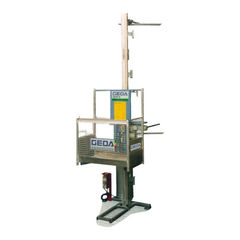
GEDA 1500 Z/ZP User manual

Page 1 of 114 Rev.: 004
BL 076 GB Translation of the original operating manual 2011 / 03
Operating Manual
Construction hoist / transport platform
For persons and loads

GEDA®1500 Z / ZP
Page 2 of 114 Rev.: 004
BL 076 GB Translation of the original operating manual 2011 / 03

GEDA®1500 Z / ZP
Page 3 of 114 Rev.: 004
BL 076 GB Translation of the original operating manual 2011 / 03
EC Declaration of Conformity
1GUIDE..........................................................................................................................7
1.1 IMAGES .............................................................................................................................................. 7
1.2 WARNINGS......................................................................................................................................... 7
1.3 OVERVIEW OF WARNINGS IN THE MANUAL............................................................................................. 8
1.3.1 Electric shock............................................................................................................................... 8
1.3.2 Crushing by car............................................................................................................................ 8
1.3.3 Do not use the hoist if there is a fire ............................................................................................ 8
1.3.4 Reaching into the travel path during operation............................................................................ 8
1.3.5 Secure machine against being switched on ................................................................................ 9
1.3.6 Falling tools/parts......................................................................................................................... 9
1.3.7 Fall and trip hazard...................................................................................................................... 9
1.3.8 Suspended loads......................................................................................................................... 9
1.3.9 Prevent access for unauthorised persons ................................................................................... 9
1.3.10 Wear safety clothing.............................................................................................................. 10
1.4 ABBREVIATIONS................................................................................................................................11
1.5 IMPRINT ........................................................................................................................................... 11
2IDENTIFICATION DATA............................................................................................12
2.1 MACHINE.......................................................................................................................................... 12
2.2 MANUFACTURER............................................................................................................................... 12
2.3 GEDA REPRESENTATIVES ................................................................................................................ 13
2.4 ORDERING SPARE PARTS .................................................................................................................. 13
3TECHNICAL DATA....................................................................................................14
3.1 SPEEDS ........................................................................................................................................... 14
3.2 DRIVES ............................................................................................................................................ 14
3.3 ASSEMBLY HEIGHT............................................................................................................................ 14
3.4 EMISSIONS ....................................................................................................................................... 14
3.5 DIMENSIONS AND WEIGHT ................................................................................................................. 15
3.5.1 Base unit:................................................................................................................................... 15
3.5.2 Platform A .................................................................................................................................. 15
3.5.3 Platform B .................................................................................................................................. 15
3.5.4 Platform BL ................................................................................................................................ 16
3.5.5 Platform BS................................................................................................................................ 16
3.5.6 Platform BLL .............................................................................................................................. 16
3.5.7 Platform C.................................................................................................................................. 17
3.5.8 Platform D.................................................................................................................................. 17
3.5.9 Platform E .................................................................................................................................. 17
3.5.10 Platform F.............................................................................................................................. 18
3.5.11 Platform G.............................................................................................................................. 18
3.5.12 Platform H.............................................................................................................................. 18
3.5.13 Platform I ............................................................................................................................... 19
3.5.14 Mast....................................................................................................................................... 19
3.5.15 Inclination of mast.................................................................................................................. 19
3.6 LANDING LEVEL SAFETY GATES.......................................................................................................... 19
3.7 TIGHTENING TORQUES ...................................................................................................................... 20
3.7.1 Mechanical fittings without tightening-torque control................................................................. 20
3.7.2 Mechanical screw connections with torque control ................................................................... 20
3.7.3 Electrical screw connections (metal screw connections)........................................................... 20
3.8 SAFETY DISTANCE TO LIVE WIRES ...................................................................................................... 20
3.9 TECHNICAL INFORMATION FOR ASSEMBLY .......................................................................................... 21
3.9.1 Foundation................................................................................................................................. 21
3.9.2 Ground pressure........................................................................................................................ 21
3.9.3 European wind regions.............................................................................................................. 22
3.9.4 Assembly geometry ................................................................................................................... 23
3.9.5 Anchoring forces........................................................................................................................ 25
3.9.6 Reinforcing tubes....................................................................................................................... 28
3.9.7 Operating materials.................................................................................................................... 29
3.9.8 Electrics...................................................................................................................................... 29
3.9.9 Tests .......................................................................................................................................... 30

GEDA®1500 Z / ZP
Page 4 of 114 Rev.: 004
BL 076 GB Translation of the original operating manual 2011 / 03
3.9.10 Operating and environmental conditions............................................................................... 30
4SAFETY INFORMATION...........................................................................................31
4.1 PROPER USE.................................................................................................................................... 31
4.2 MACHINE LIMITS ............................................................................................................................... 31
4.3 CONVERSIONS/ALTERATIONS............................................................................................................. 31
4.4 LINKING TO OTHER MACHINERY.......................................................................................................... 32
4.5 PROHIBITION OF CERTAIN ACTIVITIES ................................................................................................. 32
4.6 MACHINE OPERATION........................................................................................................................ 32
4.7 FORESEEABLE MISUSE...................................................................................................................... 32
4.8 MACHINE HAZARDS........................................................................................................................... 33
4.9 HAZARD SOURCES/RESIDUAL HAZARDS.............................................................................................. 33
4.9.1 Mobile, rotating, pointed and sharp-edged parts....................................................................... 33
4.9.2 Power sources/energy............................................................................................................... 33
4.9.3 Operating materials.................................................................................................................... 33
4.9.4 Emergency................................................................................................................................. 33
4.10 OTHER APPLICABLE DOCUMENTS....................................................................................................... 34
4.11 EXPORT LICENCE.............................................................................................................................. 34
4.12 WARRANTY ...................................................................................................................................... 34
4.13 GEDA TRAINING SESSIONS............................................................................................................... 34
5OBLIGATIONS OF THE OPERATING COMPANY...................................................35
5.1 DUTY TO INSTRUCT/PROVIDE QUALIFICATIONS.................................................................................... 35
5.2 ACCESSIBILITY TO NECESSARY INFORMATION..................................................................................... 36
5.3 INSPECTING CORRECT AND PROPER CONDITION AND USE.................................................................... 36
5.4 ESTABLISHING HAZARDS AT THE PLACE OF USE .................................................................................. 36
5.5 MACHINES/INSTALLATIONS THAT ARE SUBJECT TO REGISTRATION........................................................ 36
5.6 RECURRING INSPECTIONS................................................................................................................. 36
5.7 TRANSPORTING SUSPENDED LOADS OVER THE MACHINE..................................................................... 37
5.8 PREPARING AN EMERGENCY/EVACUATION PLAN ................................................................................. 37
5.9 INSTRUCTING ASSEMBLY ENGINEERS FROM OTHER COMPANIES........................................................... 37
5.10 FOLLOW THE INSTRUCTIONS OF GEDA ASSEMBLY ENGINEERS............................................................ 37
5.11 PROVISION OF PERSONAL PROTECTIVE GEAR ..................................................................................... 37
6FOR USE BY AUTHORISED PEOPLE......................................................................38
6.1 OPERATOR....................................................................................................................................... 38
6.2 SUPERVISOR.................................................................................................................................... 38
6.3 SPECIALISTS FOR MAINTENANCE/SERVICING....................................................................................... 38
6.4 PROTECTION OF PARTICULAR GROUPS............................................................................................... 38
6.4.1 Young people, pregnant women, disabled people .................................................................... 38
6.4.2 People with pacemakers and metal implants ............................................................................ 38
7OBLIGATORY SAFETY INSTRUCTIONS.................................................................39
7.1 BASIC CONDUCT WHILE WORKING WITH THE MACHINE ......................................................................... 39
7.2 SUPPLEMENTARY SAFETY INSTRUCTIONS -TRANSPORTING THE MACHINE/DISPOSING OF THE MACHINE.. 40
7.3 SUPPLEMENTARY SAFETY INSTRUCTIONS -SET UP AND CONNECTION/INSTALLATION............................. 41
7.4 SUPPLEMENTARY SAFETY INSTRUCTIONS -FIRST COMMISSIONING/DAILY COMMISSIONING .................... 42
7.5 SUPPLEMENTARY SAFETY INSTRUCTIONS –TRANSPORTING PERSONS ................................................. 43
7.6 SUPPLEMENTARY SAFETY INSTRUCTIONS -TRANSPORTING MATERIALS................................................ 44
7.7 SUPPLEMENTARY SAFETY INSTRUCTIONS SERVICING/REPAIRS/MAINTENANCE...................................... 45
7.8 SAFETY INSTRUCTIONS FOR CLEANING............................................................................................... 46
7.9 SAFE CONDUCT IN AN EMERGENCY .................................................................................................... 47
7.9.1 Hazard area can be left.............................................................................................................. 47
7.9.2 Hazard area cannot be left......................................................................................................... 47
7.10 SUPPLEMENTARY SAFETY INSTRUCTIONS -COMPONENTS FROM OTHER MANUFACTURERS.................... 47
7.11 EXTREME WEATHER CONDITIONS....................................................................................................... 48
8BRIEF DESCRIPTION OF THE MACHINE................................................................50
9OPERATING AND CONTROL ELEMENTS ..............................................................53
9.1 MAIN SWITCH ................................................................................................................................... 53
9.2 PLATFORM CONTROL ........................................................................................................................ 53
9.3 MANUAL CONTROL............................................................................................................................ 54
9.4 CONTROL LIGHT,OVERLOAD AND ELECTRIC SOCKET........................................................................... 54
9.5 PLATFORM ACCESS GROUND STATION............................................................................................... 55
9.6 DROP TEST CONTROL ....................................................................................................................... 57
GEDA®1500 Z / ZP
Page 5 of 114 Rev.: 004
BL 076 GB Translation of the original operating manual 2011 / 03
10 SAFETY AND EMERGENCY EQUIPMENT ..............................................................58
10.1 EMERGENCY STOP...................................................................................................................... 59
10.2 TRIGGERING AN EMERGENCY STOP/SHUTTING DOWN THE MACHINE IN AN EMERGENCY................... 59
10.3 FINISHING THE EMERGENCY STOP SITUATION............................................................................... 59
10.4 DEFECT AFTER AN EMERGENCY STOP SITUATION ......................................................................... 59
10.5 LOCATION OF THE EMERGENCY STOP BUTTONS ........................................................................... 60
10.6 SAFETY STOP ................................................................................................................................... 61
10.7 SAFETY GEAR................................................................................................................................... 61
10.8 EMERGENCY LIMIT SWITCHES........................................................................................................ 61
10.9 LOCKS TO PREVENT UNAUTHORISED USE ........................................................................................... 61
10.10 EMERGENCY LOWER ................................................................................................................ 62
11 COUNTRY-SPECIFIC EQUIPMENT VARIANTS/ACCESSORIES............................63
11.1 COLLISION GRILLE ............................................................................................................................ 63
11.2 ROOF............................................................................................................................................... 63
11.3 ENCLOSURE WITH BARRIER ............................................................................................................... 64
11.4 COLD PACKAGE ................................................................................................................................65
11.5 OPERATING TIME INDICATOR ............................................................................................................. 65
12 OPERATION ..............................................................................................................66
12.1 DAILY INSPECTIONS BEFORE STARTING WORK .................................................................................... 66
12.1.1 Visual inspections.................................................................................................................. 66
12.1.2 Function tests ........................................................................................................................ 67
12.1.3 Test run by platform operator/person authorised to carry out tests and inspections............ 67
12.2 OPERATION OF THE PLATFORM ACCESS POINTS AND THE LANDING LEVEL SAFETY DOORS..................... 68
12.2.1 Base enclosure barrier (optional) .......................................................................................... 68
12.2.2 Platform access Ground station ............................................................................................ 68
12.2.3 Barrier with unloading ramp................................................................................................... 69
12.2.4 Landing gate.......................................................................................................................... 69
12.2.5 Operating as a material hoist................................................................................................. 70
12.2.6 Operating as transport platform............................................................................................. 74
13 RECOVERY OF PEOPLE LOCKED INSIDE.............................................................76
13.1 BASIC CONDUCT IN THE EVENT OF A RESCUE/MALFUNCTION................................................................ 76
13.2 RESCUE MEASURES PLAN.................................................................................................................. 77
13.3 RESCUING PEOPLE FROM THE PLATFORM........................................................................................... 77
14 CLEANING.................................................................................................................78
14.1 INTERNAL/EXTERNAL CLEANING OF THE MACHINE................................................................................ 78
14.2 CLEANING THE AREA AROUND THE MACHINE....................................................................................... 78
15 ASSEMBLY................................................................................................................79
15.1 TRANSPORT TO ASSEMBLY SITE......................................................................................................... 81
15.1.1 Unloading / loading the base unit using a forklift................................................................... 81
15.1.2 Unloading / loading the base unit using a crane ................................................................... 81
15.2 ASSEMBLY PLAN............................................................................................................................... 82
15.3 ASSEMBLING THE BASE UNIT.............................................................................................................. 83
15.4 ASSEMBLE CABLE BIN AND TRAILING CABLE BRACKET.......................................................................... 84
15.5 ASSEMBLY /ANCHORING THE MAST.................................................................................................... 85
15.5.1 Assemble mast bracket......................................................................................................... 86
15.5.2 Use of the assembly bridge................................................................................................... 89
15.5.3 Assemble trailing cable guide................................................................................................ 89
15.5.4 Assemble EMERGENCY limit switch bar.............................................................................. 90
15.5.5 Safeguarding loading and unloading points.......................................................................... 91
15.5.6 Assembly of landing level, limit switch bar............................................................................ 91
15.5.7 Tests after assembly / tests before initial commissioning..................................................... 91
16 DISMANTLING...........................................................................................................92
17 DISPOSAL OF THE MACHINE .................................................................................92
18 MAINTENANCE.........................................................................................................93
18.1 WARNINGS AND SAFETY INSTRUCTIONS TO BE COMPLIED WITH DURING SERVICING/REPAIRS................. 93
18.2 MAINTENANCE SCHEDULE ................................................................................................................. 95
18.3 TESTS.............................................................................................................................................. 96
18.4 REPLENISHMENT AND INSPECTION TASKS........................................................................................... 98
18.4.1 Lubrication device.................................................................................................................. 98
18.5 CHECKING FOR WEAR ....................................................................................................................... 99

GEDA®1500 Z / ZP
Page 6 of 114 Rev.: 004
BL 076 GB Translation of the original operating manual 2011 / 03
18.5.1 Drive pinion............................................................................................................................ 99
18.5.2 Gear rack............................................................................................................................... 99
18.5.3 Tracks rollers....................................................................................................................... 100
18.5.4 Drive brake .......................................................................................................................... 101
18.6 FUNCTION CHECKS ......................................................................................................................... 102
18.6.1 Safety gear .......................................................................................................................... 102
18.6.2 Drop test successful ............................................................................................................103
18.6.3 Drop test not successful ...................................................................................................... 103
18.6.4 Check the safety gear for damage ...................................................................................... 104
18.6.5 Safety gear replacement ..................................................................................................... 104
18.7 FAULT TABLE.................................................................................................................................. 105
19 DOCUMENTING THE TESTS..................................................................................107

GEDA®1500 Z / ZP
Page 7 of 114 Rev.: 004
BL 076 GB Translation of the original operating manual 2011 / 03
1 Guide
You will come across a series of illustrations and symbols while reading
this manual which are intended to help you navigate through and
understand this manual. The different meanings are explained below.
Textual notations
Meaning
Bold Emphasises particularly important
words/passages
List 1 Designates lists
oList 2 Designates lists
(brackets) Item numbers
Practical instructions Practical instructions for personnel. Always
given in chronological order
The masculine form of address is used in this manual to make reading
easier. It goes without saying that both genders are always implied and
addressed.
1.1 Images
The images used refer to a specific machine type. They may only be
a schematic representation of other machine types. The fundamental
function and operation is not affected by this.
1.2 Warnings
Activities with specific hazards (to life and limb or potential damage to the
machine) are designated by warnings. You must observe the instructions
given in the warnings.
Warning level Consequence Probability
Death/serious injury is immediately pending
Serious injury possible
Slight injury possible
Material damage possible
HAZARD
W
ARNING
CAUTION
CAUTION

GEDA®1500 Z / ZP
Page 8 of 114 Rev.: 004
BL 076 GB Translation of the original operating manual 2011 / 03
1.3 Overview of warnings in the manual
1.3.1 Electric shock
1.3.2 Crushing by car
HAZARD
Life-threatening hazard
through crushing.
Never stand underneath the car (platform) / in
the hazard area during operation.
Turn the master switch off and secure against
being switched back on while working in the
hazard area.
1.3.3 Do not use the hoist if there is a fire
1.3.4 Reaching into the travel path during operation
HAZARD
Electric shock
Parts remain live even after pressing the
EMERGENCY STOP or after turning off the
machine at the main switch.
This applies to all work on electrical parts.
Disconnect mains supply upstream from the
main switch.
HAZARD
Life-threatening hazard
Do not use the hoist if there is a fire.
HAZARD
Life-threatening hazard
Crushing or amputation of limbs.
Never reach into the travel path of the machine
during operation.

GEDA®1500 Z / ZP
Page 9 of 114 Rev.: 004
BL 076 GB Translation of the original operating manual 2011 / 03
1.3.5 Secure machine against being switched on
1.3.6 Falling tools/parts
1.3.7 Fall and trip hazard
1.3.8 Suspended loads
1.3.9 Prevent access for unauthorised persons
HAZARD
Life-threatening hazard
Due to the machine being switched on during
servicing/repair work or when there is a defect.
Secure the main switch with a padlock to
prevent it being switched on.
HAZARD
Life-threatening hazard
Falling tools/parts
Secure tools / parts against falling
Use the platform.
WARNING
Fall and trip hazard
Look out for steps and objects on the ground
when entering/exiting the platform.
WARNING
Life-threatening hazard
Raised load.
Do not stand under a suspended load.
Do not stand on a suspended load.
Only raise the load at the sling points.
Only use suitable hoisting gear.
WARNING
Life-threatening hazard
Access only for authorised persons.
Access prohibited for unauthorised persons.

GEDA®1500 Z / ZP
Page 10 of 114 Rev.: 004
BL 076 GB Translation of the original operating manual 2011 / 03
1.3.10 Wear safety clothing
HAZARD
Life-threatening hazard
Risk of fire and explosion due to the use of
combustible cleaning agents.
Only use suitable, non-combustible cleaning
agents.
Do not use steam-jet equipment/high-pressure
cleaners. Electrical components can be damaged.
Do not touch sockets, cables or electrical
components with wet or damp hands.
Cleaning work on live components may only be
carried out by qualified electrical personnel.
Wear personal protective gear.

GEDA®1500 Z / ZP
Page 11 of 114 Rev.: 004
BL 076 GB Translation of the original operating manual 2011 / 03
1.4 Abbreviations
The following abbreviations may be used in the manual.
max. maximum
min. minimum
Min. Minutes
etc. et cetera
poss. possible/possibly
e.g. for example
ml Millilitre
mm Millimetre
°C degrees Celsius
°F degrees Fahrenheit
ft. feet
ft/m Feet per minute
m/min Metres per minute
inch inch
etc. et cetera
lbs. pounds
lbf.-ft Pounds per feet
Kg Kilogram
L Litre
gal. gallons
Kip. kilopound
Nm Newton metre
km/h kilometres per hour
mph Miles per hour
incl. including
if nec. if necessary
i.e. id est (that is)
reg. regarding
r. h. relative humidity
approx. approximately
Ø Diameter
® registered trademark
© Copyright
TM Trademark
% percent
‰ Promille parts per
thousand
dB (A) Sound pressure level
LWA Noise capacity level
> greater than
< less than
± plus/minus
1.5 Imprint
GEDA Dechentreiter GmbH & Co. KG
Copyright ©
All rights reserved. No part may be reproduced in any form or processed,
duplicated or disseminated using electronic media without the written
permission of the manufacturer. Observe the copyright and user conditions
of any software products/user documentation from other manufacturers
that may be included in the scope of delivery.

GEDA®1500 Z / ZP
Page 12 of 114 Rev.: 004
BL 076 GB Translation of the original operating manual 2011 / 03
2 Identification data
2.1 Machine
Machine type GEDA 1500 Z/ZP
Year of
manufacture
Refer to rating plate
2.2 Manufacturer
GEDA Dechentreiter GmbH & Co. KG
Road/street: Mertinger Strasse 60
Town/city: D-86663 Asbach-Bäumenheim
Country: Germany
Tel.: ++ 49 (0)9 06 / 98 09-0
Fax: ++ 49 (0)9 06 / 98 09-50
E-Mail: [email protected]
Website: www.geda.de

GEDA®1500 Z / ZP
Page 13 of 114 Rev.: 004
BL 076 GB Translation of the original operating manual 2011 / 03
2.3 GEDA representatives
Northwest branch East branch
GEDA Dechentreiter GmbH & Co. KG
Marie-Curie-Strasse 11
D-59192 Bergkamen-Rünthe
Tel. +49(0)2389 9874-32
Fax +49(0)2389 9874-33
GEDA Dechentreiter GmbH & Co. KG
Ernst-M.-Jahr Strasse 5
D-07552 Gera
Tel. +49(0)365 55280-0
Fax +49(0)365 55280-29
GEDA USA, LLC GEDA RUSSIA
P.O. BOX 752086
USA 77275 Houston, Texas
Tel. +1(713) 621 7272
Fax +1(713) 621 7279
Yaroslavskoe shosse 42
129337 Moscow
Tel. +7 (495) 663 24 48
Fax + 7(495) 663 24 49
2.4 Ordering spare parts
Spare parts are ordered exclusively through the
manufacturer/representative.
Only original GEDA spare parts may be used! Only original GEDA spare
parts guarantee full function as well as safety and reliability. The use of
unapproved spare parts releases us from any liability for damage arising
as a consequence of such use.
Please supply the following with each spare parts' order:
Machine type
Year of manufacture
Serial No.
Name of the component
Item No.
Order quantity
Operating voltage (if applicable)

GEDA®1500 Z / ZP
Page 14 of 114 Rev.: 004
BL 076 GB Translation of the original operating manual 2011 / 03
3 Technical data
3.1 Speeds
Hoisting speed
Construction hoist 24 m / min.
(External control)
Transport platform / Assembly 12 m / min.
(Platform control)
In the safety area
(0 – 2 m above the ground) 12 m / min.
Safety gear
Trigger speed 40 m / min.
3.2 Drives
400 V
Output 2 x 3 / 6.1 kW (6.0 / 12.2 KW)
Power consumption 2 x 7.5/13.8 A (15 / 27.6 A)
Start up current (max.) 95/ 60 A
3.3 Assembly height
max. 100 m
3.4 Emissions
LWA noise capacity level:

GEDA®1500 Z / ZP
Page 15 of 114 Rev.: 004
BL 076 GB Translation of the original operating manual 2011 / 03
3.5 Dimensions and weight
NOTE
Due to the attachment of auxiliary equipment (such as e.g. roof, assembly
web etc.) the tare weight is increased. Hereby, the payload is accordingly
reduced.
3.5.1 Base unit:
Weight (without platform) 970 kg
3.5.2 Platform A
Payload (max.)
Construction Hoist 2,000 kg
Transport platform 2,000 kg
(max. 7 people)
1,900 kg + 1
1,800 kg + 2
1,700 kg + 3
1,600 kg + 4
1,500 kg + 5
1,400 kg + 6
1,300 kg + 7
Assembly 1,000 kg
Dimensions 1.45 x 1.65 x 1.1/1.8 m
Weight (with base unit) 1,370 kg
Number of entrances 1 x load; 1x unload
3.5.3 Platform B
Payload (max.)
Construction Hoist 1,500 kg
Transport platform 1,500 kg
(max. 7 people)
1,400 kg + 1
1,300 kg + 2
1,200 kg + 3
1,100 kg + 4
1,000 kg + 5
900 kg + 6
800 kg + 7
Assembly 500 kg
Dimensions 1.45 x 3.35 x 1.1/1.8 m
Weight (with base unit) 1,580 kg
Number of entrances 1 x load; 1x unload

GEDA®1500 Z / ZP
Page 16 of 114 Rev.: 004
BL 076 GB Translation of the original operating manual 2011 / 03
3.5.4 Platform BL
Payload (max.)
Construction Hoist 1,200 kg
Transport platform 1,200 kg
(max. 7 people)
1,100 kg + 1
1,000 kg + 2
900 kg + 3
800 kg + 4
700 kg + 5
600 kg + 6
500 kg + 7
Assembly 500 kg
Dimensions 1.45 x 4.15 x 1.1/1.8 m
Weight (with base unit) 1,670 kg
Number of entrances 1 x load; 1x unload
3.5.5 Platform BS
Payload (max.)
Construction Hoist 2,000 kg
Transport platform 2,000 kg
(max. 7 people)
1900 kg + 1
1,800 kg + 2
1,700 kg + 3
1,600 kg + 4
1,500 kg + 5
1,400 kg + 6
1,300 kg + 7
Assembly 500 kg
Dimensions 1.45 x 3.35 x 1.1/1.8 m
Weight (with base unit) 1,580 kg
Number of entrances 1 x load; 1x unload
3.5.6 Platform BLL
Payload (max.)
Construction Hoist 850 kg
Transport platform 850 kg
(max. 7 people)
750 kg + 1
650 kg + 2
550 kg + 3
450 kg + 4
350 kg + 5
250 kg + 6
150 kg + 7
Assembly 500 kg
Dimensions 1.45 x 4.95 x 1.1/1.8 m
Weight (with base unit) 1,840 kg
Number of entrances 1 x load; 1x unload

GEDA®1500 Z / ZP
Page 17 of 114 Rev.: 004
BL 076 GB Translation of the original operating manual 2011 / 03
3.5.7 Platform C
Payload (max.)
Construction Hoist 2,000 kg
Transport platform 2,000 kg
(max. 7 people)
1,900 kg + 1
1,800 kg + 2
1,700 kg + 3
1,600 kg + 4
1,500 kg + 5
1,400 kg + 6
1,300 kg + 7
Assembly 1,000 kg
Dimensions 2.9 x 1.65 x 1.1/1.8 m
Weight (with base unit) 1,560 kg
Number of entrances 2 x load; 1x unload
3.5.8 Platform D
Payload (max.)
Construction Hoist 2,000 kg
Transport platform 2,000 kg
(max. 7 people)
1,900 kg + 1
1,800 kg + 2
1,700 kg + 3
1,600 kg + 4
1,500 kg + 5
1,400 kg + 6
1,300 kg + 7
Assembly 1,000 kg
Dimensions 2.9 x 1.65 x 1.1/1.8 m
Weight (with base unit) 1,560 kg
Number of entrances 2 x load; 1x unload
3.5.9 Platform E
Payload (max.)
Construction Hoist 2,000 kg
Transport platform 1,500 kg
(max. 7 people)
1,400 kg + 1
1,300 kg + 2
1,200 kg + 3
1,100 kg + 4
1,000 kg + 5
900 kg + 6
800 kg + 7
Assembly 1,000 kg
Dimensions 2.9 x 1.65 x 1.1/1.8 m
Weight (with base unit) 1,635 kg
Number of entrances 2 x load; 2x unload

GEDA®1500 Z / ZP
Page 18 of 114 Rev.: 004
BL 076 GB Translation of the original operating manual 2011 / 03
3.5.10 Platform F
Payload (max.)
Construction Hoist 2,000 kg
Transport platform 1,500 kg
(max. 7 people)
1,400 kg + 1
1,300 kg + 2
1,200 kg + 3
1,100 kg + 4
1,000 kg + 5
900 kg + 6
800 kg + 7
Assembly 1,000 kg
Dimensions 4.35 x 1.65 x 1.1/1.8 m
Weight (with base unit) 1,785 kg
Number of entrances 2 x load; 1x unload
3.5.11 Platform G
Payload (max.)
Construction Hoist 2,000 kg
Transport platform 1,500 kg
(max. 7 people)
1,400 kg + 1
1,300 kg + 2
1,200 kg + 3
1,100 kg + 4
1,000 kg + 5
900 kg + 6
800 kg + 7
Assembly 1,000 kg
Dimensions 4.35 x 1.65 x 1.1/1.8 m
Weight (with base unit) 1,785 kg
Number of entrances 2 x load; 1x unload
3.5.12 Platform H
Payload (max.)
Construction Hoist 2,000 kg
Transport platform 1,500 kg
(max. 7 people)
1,400 kg + 1
1,300 kg + 2
1,200 kg + 3
1,100 kg + 4
1,000 kg + 5
900 kg + 6
800 kg + 7
Assembly 1,000 kg
Dimensions 4.35 x 1.65 x 1.1/1.8 m
Weight (with base unit) 1,840 kg
Number of entrances 2 x load; 2x unload

GEDA®1500 Z / ZP
Page 19 of 114 Rev.: 004
BL 076 GB Translation of the original operating manual 2011 / 03
3.5.13 Platform I
Payload (max.)
Construction Hoist 2,000 kg
Transport platform 1,500 kg
(max. 7 people)
1,400 kg + 1
1,300 kg + 2
1,200 kg + 3
1,100 kg + 4
1,000 kg + 5
900 kg + 6
800 kg + 7
Assembly 1,000 kg
Dimensions 4.35 x 1.65 x 1.1/1.8 m
Weight (with base unit) 1,785 kg
Number of entrances 2 x load; 1x unload
3.5.14 Mast
Length 1.5 m
Weight 44 kg
Tightening torque, bolts 150 Nm
First mast anchoring max. 6 m
Vertical distance mast anchorings max. 10 m
Vertical distance trailing cable guide max. 6 m
Projecting mast length max. 6 m (platform A, C-I)
Projecting mast length max. 2 m
(platform B, BS, BL, BLL)
3.5.15 Inclination of mast
Vertical inclination of the mast max. 0.5°. Check inclination during and
following installation using appropriate means.
3.6 Landing level safety gates
The hoist GEDA 1500 Z/ZP has been type-tested together with the GEDA
landing-level safety gates:
GEDA COMFORT Item No. 01212
GEDA STANDARD Item No. 01217
GEDA STANDARD Basic Item No. 01268
and fulfils the requirements for safe transfer between landing level and
platform. GEDA lifts with type test certification must also only be used in
combination with tested GEDA landing-level gates. For assembly of the
landing-level safety gates, refer to the corresponding manual.

GEDA®1500 Z / ZP
Page 20 of 114 Rev.: 004
BL 076 GB Translation of the original operating manual 2011 / 03
3.7 Tightening torques
3.7.1 Mechanical fittings without tightening-torque control
All information refers to bolts in strength class 8.8
Tightening
torque
Tightening torque
M 8 25 Nm M 16 210 Nm
M 10 49 Nm M 18 300 Nm
M 12 86 Nm M 20 425 Nm
M 14 135 Nm M 24 710 Nm
3.7.2 Mechanical screw connections with torque control
Mast elements to one another
150 Nm Tightening torque
Mast tubes
50 Nm Tightening torque
3.7.3 Electrical screw connections (metal screw connections)
Tightening
torque
Tightening torque
M 4 1.2 Nm M 12 15.5 Nm
M 5 2 Nm M 16 30 Nm
M 6 3 Nm M 20 52 Nm
M 8 6 Nm M 24 52 Nm
M 10 10 Nm M 30 52 Nm
3.8 Safety distance to live wires
The table below shows the minimum safety distances between each
machine component and live, non-insulated wires. Observe the country
specific regulations.
Voltage Minimum distance
0 – 300 V Avoid contact
> 300 V to 50 kV 3.0 m
> 50 kV to 200 kV 4.5 m
> 200 V to 350 kV 6.0 m
> 350 V to 500 kV 8.0 m
> 500 V to 750 kV 11.0 m
> 750 V to 1000 kV 14.0 m
Table of contents
Other GEDA Lifting System manuals

GEDA
GEDA STAR 200 STANDARD User instructions

GEDA
GEDA AB 450 User manual

GEDA
GEDA MAXI 120 S User instructions

GEDA
GEDA AB 450 User instructions

GEDA
GEDA 3700 Z User manual

GEDA
GEDA PH 650 Installation instructions

GEDA
GEDA 300 Z User manual

GEDA
GEDA COMBILIFT 250 Z User manual

GEDA
GEDA 300 Z User instructions