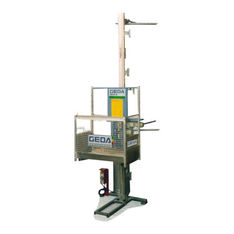
GEDA 3700 Z User manual

Assembly instruction
Assembly Instructions
Construction Hoist / Transport Platform
For persons and loads


GEDA®3700 Z/ZP Guide
ML034 GB 2017 / 11 Page 3 of 60 Assembly Instructions
Table of Contents
1GUIDE............................................................................................................................................................... 5
2IDENTIFICATION DATA .................................................................................................................................. 6
2.1 MACHINE ................................................................................................................................................... 6
3FOR PERSONS AUTHORISED TO CARRY OUT ASSEMBLY TASKS ........................................................ 7
3.1 ASSEMBLY,SERVICING /MAINTENANCE SPECIALIST ....................................................................................... 7
3.2 OBLIGATORY SAFETY INSTRUCTIONS WHILST WORKING WITH THE MACHINE..................................................... 7
3.3 TRANSPORTATION OF THE MACHINE ............................................................................................................. 7
3.4 SET UP AND CONNECTION/ASSEMBLY ........................................................................................................... 8
3.5 INITIAL OPERATION/DAILY OPERATION........................................................................................................... 8
4TRANSPORT / STORAGE............................................................................................................................... 9
4.1 CHECKS UPON RECEIPT OF THE TRANSPORT PLATFORM............................................................................... 10
4.2 TRANSPORT DIMENSIONS /TRANSPORT WEIGHTS ....................................................................................... 10
4.3 LOADING AND UNLOADING THE MACHINE ..................................................................................................... 11
4.3.1 Lifting with a forklift truck................................................................................................................... 12
4.3.2 Lifting with a crane ............................................................................................................................ 12
4.4 ASSEMBLY BEFORE AND AFTER TRANSPORTATION BY LORRY........................................................................ 13
5ELECTRICAL CONNECTED LOADS............................................................................................................ 16
6ASSEMBLY .................................................................................................................................................... 18
6.1 ASSEMBLY DRAWINGS............................................................................................................................... 18
6.2 FOUNDATION /SUBSTRUCTURE ................................................................................................................. 18
6.3 OPERATION FOR ASSEMBLY....................................................................................................................... 20
6.4 ASSEMBLY PLANK ..................................................................................................................................... 22
6.5 ASSEMBLY CAR ........................................................................................................................................ 24
6.6 ASSEMBLY PROCEDURE ............................................................................................................................ 25
6.7 ASSEMBLING THE BASE UNIT...................................................................................................................... 26
6.7.1 Base enclosure with barriers (optional)............................................................................................. 27
6.7.2 Roof for all platforms ......................................................................................................................... 28
6.7.3 Connecting / switching on the electrical components........................................................................ 33
6.7.4 Assembling the mast assembly aid ................................................................................................... 36
6.8 ASSEMBLY /ANCHORING THE MAST ............................................................................................................ 38
6.8.1 Assembling mast sections................................................................................................................. 39
6.8.2 Travelling cable guides...................................................................................................................... 42
6.8.3 Tie forces........................................................................................................................................... 44
6.8.4 Installing the mast tie......................................................................................................................... 48
6.9 ASSEMBLING THE CABLE CARRIAGE AND CENTRAL FEEDER (OPTIONAL) ......................................................... 49
6.9.1 Installing the cable carriage............................................................................................................... 49
6.9.2 Installing the central feeder and travelling cable ............................................................................... 50
6.10 LIMIT SWITCH APPROACH BAR.................................................................................................................... 54
6.10.1 Landing limit switch, approach bar ............................................................................................... 54
6.10.2 EMERGENCY limit switch approach bar ...................................................................................... 55
6.11 LANDING LEVEL SAFETY GATES .................................................................................................................. 56
6.11.1 Assembly of the electric modules ................................................................................................. 57
6.12 CHECK AFTER ASSEMBLY AND BEFORE EACH OPERATION............................................................................. 58
6.12.1 Train authorized personnel ........................................................................................................... 58
7DISMANTLING (DISASSEMBLY).................................................................................................................. 59

Guide GEDA®3700 Z/ZP
Assembly Instructions Page 4 of 60 ML034 GB 2017 / 11

GEDA®3700 Z/ZP Guide
ML034 GB 2017 / 11 Page 5 of 60 Assembly Instructions
1 Guide
You will see a series of illustrations and symbols whilst reading this
manual which are intended to help you navigate through and understand
it. The different meanings are explained below.
Text display
Meaning
Bold type
Emphasises particularly important
words/passages
•List 1
Denotes lists
oList 2
Denotes lists
(brackets)
Position numbers
Handling instruction
Instruction to personnel. Always given in
chronological order
For an easier reading style, we mostly use the masculine form in this
manual. It goes without saying that both genders are always implied and
addressed.
Images
The illustrations used refer to a specific machine type. They may only
constitute a schematic representation with other machine types. The
fundamental function and operation are not affected by this.
Warnings
Activities associated with specific hazards (to life and limb or potential
damage to the machine) are indicated by warnings. The instructions given
in the warnings must be observed.
Warning level
Consequence
Probability
DANGER Death/serious injury is imminent
WARNING Serious injury possible
CAUTION Minor injury possible
CAUTION
Tangible damage possible
Attention information
This is found at points where special information or rules and prohibitions
regarding damage prevention are given in order to prevent damage to the
machine.
Note
This is found at points where information is given about using the machine
economically or instructions are given regarding correct working
procedures.

Identification data GEDA®3700 Z/ZP
Assembly Instructions Page 6 of 60 ML034 GB 2017 / 11
Abbreviations
The following abbreviations may be used in the manual.
max. maximum
min. minimum
mins minutes
etc. et cetera
poss. possible/possibly
e.g. for example
ml millilitres
mm millimetres
°C degrees Celsius
°F degrees
Fahrenheit
ft. feet
ft/m feet per minute
m/min metres per minute
in. inches
etc. et cetera
lbs. pounds
lbf.-ft pounds per feet
kg kilogram
l litre
gal. gallons
kip. kilopound
Nm Newton metre
km/h kilometres per hour
mph miles per hour
incl. including
if nec. if necessary
i.e. id est (that is)
reg. regarding
RH relative humidity
approx. approximately
Ø diameter
® registered trademark
© copyright
TM trademark (trade name)
% per cent
‰ per thousand
dB (A) sound pressure level
LWA sound power level
> greater than
< less than
± plus or minus
NN Sea level
2 Identification data
2.1 Machine
Machine model GEDA 3700 Z/ZP
Works number:
32T0101 –
31T0101
Year of construction: Refer to identification plate
Documentation version: 11/2017

GEDA®3700 Z/ZP For persons authorised to carry out assembly tasks
ML034 GB 2017 / 11 Page 7 of 60 Assembly Instructions
3 For persons authorised to carry out assembly tasks
3.1 Assembly, servicing / maintenance specialist
A person who, due to qualified professional education, training and
experience, is able to recognise risks and potential hazards during
work/assembly/maintenance/repair work on the machine or
subcomponents and can rectify these by introducing appropriate
measures.
3.2 Obligatory safety instructions whilst working with the machine
•Also observe the safety notes in the instruction manual.
•The machine must not be used as steps or a climbing aid. Only use
tested and stable steps/climbing aids. Keep steps/climbing aids free of
dirt and soiling.
•At the end of work or if work is interrupted, the machine must be turned
off at the main switch and secured against unauthorised switch-on
(e.g. with a padlock).
3.3 Transportation of the machine
•No persons must remain in the area below or on the raised
machine/parts of the machine.
•Only lift the machine using the necessary parts and at the specified
mooring points.
•The machine must only be transported/installed on foundations with a
sufficient load capacity.
•Ensure that stable balance is maintained when transporting with forklift
trucks.

For persons authorised to carry out assembly tasks GEDA®3700 Z/ZP
Assembly Instructions Page 8 of 60 ML034 GB 2017 / 11
3.4 Set up and connection/assembly
•Precautionary measures stipulated by the company for avoiding fires,
explosions, dust, gas, steam and smoke (during welding, burning and
grinding work) must be observed.
•Personnel must be acquainted with the on-site working environment,
e.g. obstacles in the work and traffic areas, ground load bearing
capacity and necessary barriers between the construction site and
public areas.
•Appropriate lifting gear must be used when working with heavy parts.
•Adhere to the minimum requirements for thoroughfares, paths and
emergency exits.
•Provide sufficient space to open gates and covers.
•Welding, burning and grinding work on the machine must only be
carried out following consultation with and approval from GEDA.
•Make sure that the masonry is capable of absorbing the tie forces.
A construction expert must check to ensure the house front is suitable
for tie forces of this kind. The inspection results will determine whether
plugs/dowels or through bolts must be used.
•In the event of wind speeds ≥ 45 km/h, bring the car down to the ground
and cease operation.
3.5 Initial operation/daily operation
Ensure that:
•All safety covers and safety equipment are present and functioning.
•All connections are correctly connected.
•All parts are correctly installed.
•No tools or other parts are inside or on the machine.
•No tools or other parts are located in the path of travel of the machine.
•All warning signs and instructions on the machine are present and
complete, clearly visible and undamaged.
•Illegible or missing warning signs and instructions must be replaced
immediately.
•Before operation, carry out the checks stipulated in the national
regulations.

GEDA®3700 Z/ZP Transport / storage
ML034 GB 2017 / 11 Page 9 of 60 Assembly Instructions
4 Transport / storage
The transport platform should be transported by experienced and
competent persons.
•During transportation, the platform must be empty.
•Only carefully load and transport equipment that has been
disassembled, packaged and lashed.
Observe the national requirements for securing loads
•Always ensure that the machine is transported without being knocked
or jolted. Make sure that the machine is stable during transportation.
Support the platform before lashing down for transportation.
•Always secure transported loads against falling or tipping over!
Storage:
Temperature range: minimum -20 °C
maximum +40 °C
Air humidity (relative): 80 % RH.
•Store in dry rooms.
•No jolts or vibrations.
•No abrasive, corrosive substances.
•The machine must be protected against pest damage (insects, rodents,
etc.).
•Before transportation/storage, the machine must be cleaned and
checked for signs of damage.

Transport / storage GEDA®3700 Z/ZP
Assembly Instructions Page 10 of 60 ML034 GB 2017 / 11
4.1 Checks upon receipt of the transport platform
•Check the shipment for transport damage and for completeness
according to the purchase order.
•Dispose of packaging/protective coverings according to legal
requirements or keep them for later transport.
•Immediately notify the freight carrier (haulage company) and dealer of
any transport damage.
4.2 Transport dimensions / Transport weights
GEDA 3700 Z/ZP with
Length
Width
Height
Weight
(max.)
Platform “A”
Base unit with platform and
cable bin (100 m)
2.43 m
4.75 m
2.70 m
1)2.55 m
3870 kg
Platform “B”
Base unit with platform and
cable bin (100 m)
3.38 m
4.75 m
4080 kg
Platform “C”
Base unit with platform and
cable bin (100 m)
4.33 m
4.75 m
4290 kg
Platform “D”
Base unit with platform and
cable bin (100 m)
5.28 m
4.75 m
4500 kg
Travelling cable, 25 m
each
+ 41 kg
Mast section (1.5 m)
1.5 m
88 kg
•1) = Height for loading on a container (base unit lowered by 15 cm)
•Height (container) = 2.59 m
•

GEDA®3700 Z/ZP Transport / storage
ML034 GB 2017 / 11 Page 11 of 60 Assembly Instructions
4.3 Loading and unloading the machine
The machine sections/components are loaded and unloaded using a
forklift truck or a crane.
WARNING
Danger to life
Raised load!
Do not stand under suspended loads.
Do not stand on a suspended load.
Only lift loads at the slinging points.
Only use suitable lifting gear.
•During the loading tasks, wear a safety helmet, safety shoes and
safety gloves!
•Only use appropriate, standardised and tested lifting gear (forklift
trucks) and slinging gear (round slings, lifting straps, sling ropes,
chains) for transport at the assembly site.
•When selecting lifting equipment, always take into account the
maximum suspended loads!
Only lift the base unit when the platform is empty.
•For the dimensions and weights, refer to Chapter 3.2 (Technical Data).
Weight of the heaviest part of the machine (base unit with platform
“D”) approx. 4500 kg)

Transport / storage GEDA®3700 Z/ZP
Assembly Instructions Page 12 of 60 ML034 GB 2017 / 11
4.3.1 Lifting with a forklift truck
There are forklift take-up
points (1) under the
bearing profile of the
platform (below the
platform accesses).
Forklift tines must be at least 2.10 m long.
4.3.2 Lifting with a crane
For machines up to works no. 32T00100, lifting with a crane is not
intended.
1

GEDA®3700 Z/ZP Transport / storage
ML034 GB 2017 / 11 Page 13 of 60 Assembly Instructions
4.4 Assembly before and after transportation by lorry
When transporting by lorry, the platform extensions are dismantled on
platforms “B”, “C” and “D”.
Assembly
Undo and remove the connecting screws
from the platform extension (1+2).
Lift the platform extension and remove the
transport brackets (3) on both sides.
Retain the transport brackets for
subsequent transport.
3
2
1

Transport / storage GEDA®3700 Z/ZP
Assembly Instructions Page 14 of 60 ML034 GB 2017 / 11
Lift the platform extension on the base unit and secure using the
connecting screws.
Tightening torque bolts M20 = 400 Nm
When delivered, access doors and barriers are already fitted with
loading ramps. These may need to be moved when retrofitting
platform extensions.

GEDA®3700 Z/ZP Transport / storage
ML034 GB 2017 / 11 Page 15 of 60 Assembly Instructions
Route the end-switch cables from
the protection grid underneath
the hoist car to the distributor box
(4) below the base unit, and
connect them.
Route the couplings (-8EB33 + -
8EB34) to the access doors and
connect to the door lock plugs.
Route the couplings (-8EB31 + -8EB32) to the barriers with loading
ramp and connect to the ramp end switch plugs.
4

Electrical connected loads GEDA®3700 Z/ZP
Assembly Instructions Page 16 of 60 ML034 GB 2017 / 11
5 Electrical connected loads
Mains connection (refer to the
nameplate)
400 V / 50 Hz / 3 Ph/PE
480 V / 60 Hz / 3 Ph/PE
Mains fuse
3 x 63 A slow-to-blow
Protection class
IP 54 (NEMA 3)
Connection to the building site distributor in accordance with
IEC 60439-4:2005
The cables provided by the customer must be designed so that:
•They correspond to the connected load of the machine.
•No interference voltages or interference frequencies occur.
•The response behaviour of the safety equipment meets the relevant
legal requirements.
The necessary cable cross-section must be determined while taking into
account the requisite installation type according to DIN VDE 0298
Section 4 and DIN VDE 0100 Section 430. Country-specific rules must be
observed.
WARNING
The equipotential bonding for the transport platform must be
connected to the primary equipotential bonding of the building!
The machine must be integrated into the lightning protection concept
of the building.

GEDA®3700 Z/ZP Electrical connected loads
ML034 GB 2017 / 11 Page 17 of 60 Assembly Instructions
Note for machines with frequency converter
This product can cause a direct current in the protective earthing
conductor. At those places where a residual current device (RCD) or a
residual current monitor (RCM) is used for protection in the event of direct
or indirect contact, then only an RCD or RCM of Type B is permitted on
the power supply end of this product.
If the installation guidelines include a “residual current device” (residual
current circuit breaker), then you must use a “Type B” residual current
circuit breaker (all-current sensitive) for three-phase frequency converters.
Select a residual current circuit breaker with the following features:
•Filtering of high-frequency currents.
•A delay that prevents triggering caused by interference capacities which
may be charged at switch-on.
This delay is not possible on 30 mA residual current circuit breakers. In
this case, select a residual current circuit breaker that is resistant to
accidental triggering, for example a residual current circuit breaker with
enhanced immunity to interference (super-immune).
If several machines with frequency converters are operated from a mains
connection, then one residual current device (residual current circuit
breaker) must be used for each machine with a frequency converter.
WARNING
Electric shock
The frequency converter can prevent correct function or lead to
malfunctions in the “type A” residual current device.
In the event of defects e.g. in the wiring, this can lead to electric
shocks.

Assembly GEDA®3700 Z/ZP
Assembly Instructions Page 18 of 60 ML034 GB 2017 / 11
6 Assembly
6.1 Assembly drawings
If installation conditions vary, specific installation drawings can be
prepared by GEDA.
Assembly drawings supplied and released must be kept until disassembly
of the platform.
6.2 Foundation / Substructure
The foundation and load-distribution substratum(substrata) must safely
transfer any existing loads into the subsoil. Therefore, before beginning
installation task, determine the following points.
•Verification of the payload of the foundation / load-distributing
substratum (substrata).
•Verification of the load-bearing capacity of the subsoil
Since the load-bearing capacity of the subsoil is often very difficult to
estimate, a specialist subsoil investigator should be called on if there is
even the slightest doubt, in particular for high/complicated superstructures.
The following points must be taken into account when assessing the
subsoil:
•Maximum permissible soil pressure
•Predicted settlement
•Predicted groundwater levels
•Predicted thawing and frost processes
•Construction activities expected in direct proximity to the installation site
Wooden planks or steel plates can be used as load-distributing base
supports. The foundation must be horizontal to erect the mast.
The total weight (refer to table) of the transport platform and mast sections
is transferred through the foot section support under the mast in the
foundation.
The ground pressure of the different platform models is the same,
since the load bearing capacity of the platforms differ.
Load capacity (max.)
3700 kg
Mass per mast
88 kg
Length per mast
1.5 m
Height of base unit
2.7 m
Empty weight of the compl. base unit
(max.)
4500 kg
Base area without base support
(2 x 0.6 m x 1.0 m)
2 x 0.6 m²

GEDA®3700 Z/ZP Assembly
ML034 GB 2017 / 11 Page 19 of 60 Assembly Instructions
Ground pressure per mast
Assembly height in m 10 20 30 40 50 60 70 80 90 100
Total weight [kg] 6270 6830 7480 8120 8680 9310 9960 10510 11150 11790
Ground pressure [kN/m
2
] 105 114 125 136 145 156 166 176 186 197
Assembly height in m 110 120 130 140 150 160 170 180 190 200
Total weight [kg] 12350 13000 13640 14200 14480 15480 16040 16700 17350 17900
Ground pressure [kN/m2]
206
217
228
237
248
258
268
278
289
298

Assembly GEDA®3700 Z/ZP
Assembly Instructions Page 20 of 60 ML034 GB 2017 / 11
6.3 Operation for assembly
For installation, it is only possible to operate from the platform in dead
man’s control with two hands. The platform only moves for as long as the
operating buttons are pressed.
Loading doors, barriers with unloading ramp and assembly plank must be
closed and engaged. The assembly guard must be properly hung up.
The main switch (on the ground station switch box) must be
switched on (Position “I” [ON]).
1 = EMERGENCY STOP button
Put key into the key switch (5) and turn to
the right.
Only the platform control is activated for
installing the lift.
The lifting speed of the platform is approx. 12 m/min. or 24 m/min.
respectively.
Ascent
Press and hold the UP button (3).
Also press the button (2) to release the ascent.
The platform only moves while the UP (3) button and button (2) are
pressed.
Descent
1
5
3
2
4
5
This manual suits for next models
1
Table of contents
Other GEDA Lifting System manuals

GEDA
GEDA MAXI 120 S User instructions

GEDA
GEDA PH 650 Installation instructions

GEDA
GEDA 300 Z User instructions

GEDA
GEDA AB 450 User manual

GEDA
GEDA 300 Z User manual

GEDA
GEDA AB 450 User instructions

GEDA
GEDA COMBILIFT 250 Z User manual

GEDA
GEDA 1500 Z/ZP User manual

GEDA
GEDA STAR 200 STANDARD User instructions
Popular Lifting System manuals by other brands

Bike-Lift
Bike-Lift LEVANTE-50 Use and maintenance manual

QUALITY LIFTS
QUALITY LIFTS Q4P07 Installation, operation & maintenance manual

Maxon
Maxon TE-15 Operation manual

Lukas
Lukas LX LIFT operating instructions

Joerns Healthcare
Joerns Healthcare Oxford Advance User instruction manual & warranty

Post
Post PR19.150.2 Operator's manual