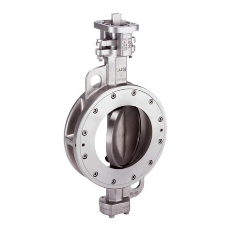
Gefa DG1 User manual

DG1
ARMATURENTECHNIK
Original instructions
Germaniastraße 28 • D-44379 Dortmund
Tel.: +49 (0)231 / 61 00 9-0 • Fax: +49 (0)231 / 61 00 9-80
Internet: www.gefa.com • E-Mail: [email protected]
Version 0 • DocID 104070923

DG1
Table of contents
1 Imprint ............................................................................................................................................................. 4
2 Safety instruction ........................................................................................................................................... 5
2.1 Used information and warning signs ........................................................................................................ 5
2.2 Intended Use............................................................................................................................................ 6
2.3 User.......................................................................................................................................................... 6
2.4 Improper use ............................................................................................................................................ 6
2.5 Due diligence of the operator ................................................................................................................... 6
2.6 Product safety .......................................................................................................................................... 7
2.7 Product-specific dangers.......................................................................................................................... 7
2.8 Outflowing media ..................................................................................................................................... 7
2.9 Failure of actuator operating power ......................................................................................................... 7
2.10 Mounting of actuators...............................................................................................................................7
3 Scope of supply.............................................................................................................................................. 8
3.1 Exploded view drawing DN8-50 ............................................................................................................... 8
3.2 Components ............................................................................................................................................. 8
3.3 Exploded view drawing DN65-100 ........................................................................................................... 9
3.4 Components ............................................................................................................................................. 9
4 Transport and storage ................................................................................................................................. 10
5 Assembly and commissioning.................................................................................................................... 11
5.1 Installation conditions.............................................................................................................................12
5.2 Installation position................................................................................................................................. 12
5.3 Initial operation.......................................................................................................................................13
5.4 Mounting instructions ............................................................................................................................. 14
5.5 Impermissible operation ......................................................................................................................... 14
6 Operation ...................................................................................................................................................... 15
7 Maintenance and repair ............................................................................................................................... 16
7.1 Maintenance........................................................................................................................................... 16
7.2 Tightening/replacing the stuffing box packing ........................................................................................ 17
7.3 Replacing the seat ................................................................................................................................. 18
8 Decommissioning and disposal ................................................................................................................. 19
8.1 Decommissioning ................................................................................................................................... 19
8.2 Removing of the valve............................................................................................................................ 19
8.3 Disposal ................................................................................................................................................. 19
9 Technical data and materials ..................................................................................................................... 20
9.1 Dimension sheet DN8-50 - full bore - threaded end and butt weld end, short ....................................... 20
9.2 Dimension sheet DN65-100 - full bore - threaded end and short butt weld end .................................... 21
9.3 Dimension sheet DN15-65 - reduced bore - threaded end and short butt weld end.............................. 22
9.4 Dimension sheet DN80-150 - reduced bore - threaded end and short butt weld end............................ 23
9.5 Dimension sheet DN8-100 - full and red. Bore - threaded end and short butt weld end with AP series
actuator .................................................................................................................................................. 24
9.6 Dimension sheet DN8-50 - full bore - long butt weld end....................................................................... 25
9.7 Dimension sheet DN8-50 - full bore - orbital end ................................................................................... 26
9.8 Dimension sheet DN65-100 - full bore - orbital end ............................................................................... 27
9.9 Dimension sheet DN10-50 - full bore - V-flange PN10-40 ..................................................................... 28
9.10 Dimension sheet DN65-100 - full bore - V-flange PN10-40 ................................................................... 29
9.11 Dimension sheet DN8-50 full / DN15-65 reduced bore with T-hand lever ............................................. 30
9.12 Dimension sheet, actuator connection DIN 3337 / ISO 5211................................................................. 31
2 / 39 Version 0 • DocID. 104070923

DG1
9.13 Materials DN8-50 full bore / DN15-65 reduced bore.............................................................................. 32
9.14 Materials DN65-100 full bore / DN80-150 reduced bore........................................................................ 33
9.15 Pressure-temperature diagram DN8-100............................................................................................... 34
9.15.1 Pressure-temperature diagram DN8-25...................................................................................... 34
9.15.2 Pressure-temperature diagram DN32-50.................................................................................... 35
9.15.3 Pressure-temperature diagram DN65-100.................................................................................. 36
10 How to proceed in case of malfunctions ...................................................................................................37
11 Annex ............................................................................................................................................................ 38
11.1 Structure of control elements ................................................................................................................. 38
11.1.1 Structure of the hand lever.......................................................................................................... 39
3 / 39
Version 0 • DocID104070923

DG1
4 / 39 Version 0 • DocID104070923
Internet: www.gefa.com • E-Mail: [email protected]
1 Imprint
Read the operating instructions thoroughly before installing your valve. Failure to follow these instructions or the
warning and safety labels could result in serious injury or property damage. These operating instructions must
be available to all users at all times. GEFA Processtechnik GmbH is not liable for unauthorized changes of the
device or for improper use.
All rights reserved GEFA Processtechnik GmbH
GEFA Processtechnik GmbH
Germaniastraße 28
44379 Dortmund, Germany
Tel: +49(0)231-61009-0
Fax: +49(0)231-61009-80
E-Mail: [email protected]

DG1
2 Safety instruction
This chapter contains basic instructions for the safe handling of this valve.
Observe all instructions for transport, storage, installation, commissioning, maintenance and decommissioning
as well as disposal. In explosive arenas, the relevant standards, the specifications of the manufacturer and the
risk assessment must be observed
Failure to observe safety instructions may result in personal injury and / or property damage.
The safety instructions in this documentation are uniform and marked with an icon on the left side of the note. A
signal word above the text indicates the hazard level. The color of the hazard word additionally signals the haz-
ard level.
The warning notice also includes:
>Nature and origin of danger.
>Possible consequences of the danger.
>Measures to avoid the danger.
If more than one hazard level occurs, the safety notice for the highest level is used.
Nature and origin of danger.
Possible consequences of the danger.
Measures to avoid the danger.
Signal words for warnings
The signal word identifies the severity of the hazard that occurs if it is not avoided.
DANGER means: Serious personal injury threatens immediately.
WARNING means: Serious personal injury may be imminent.
CAUTION means: Light / medium personal injury threatens immediately.
NOTICE means: property damage threatens directly or possibly.
2.1 Used information and warning signs
The warning sign represents a source of danger. Warning signs are located
>At the device near the source of danger.
>In the operating instructions before the activity is described, which can be a hazard.
The following information and warning signs are used in this operating manual:
Safety Notice General
Wear safety gloves
Wear safety shoes
Observe and obey all local safety regulations, safety precautions and operating instructions. These apply in ad-
dition to or in addition to the safety instructions stated and shown in this manual. If contradictory identifications
occur, speak with the responsible authority. All PPE (personal protective equipment) must be provided by the
user of the valve.
5 / 39
Version 0 • DocID 104070923
Internet: www.gefa.com • E-Mail: [email protected]

DG1
6 / 39 Version 0 • DocID104070923
Internet: www.gefa.com • E-Mail: [email protected]
2.2 Intended Use
The valve is used exclusively for shutting off, throttling and regulating media flows under the Consideration of
the data given on the valve and technical details given in this manual Data, diagrams, applications described
and only in connection with the components, which are recommended by GEFA Processtechnik GmbH, ap-
proved and mentioned in this documentation. The faultless and safe operation of the device requires proper
transport, proper storage and installation as well as careful operation and maintenance. This documentation is
part of the device and must be available at all times. Observe all safety regulations which are listed in this docu-
mentation. The valve may only be operated in such a way that no fatigue stress occurs. Max. 500 load changes
at Δp = PS or max. 500 / (Δp / PS) ³ permissible partial load changes (see DIN EN 13445-3 section 5.4.2). The
valve may only be operated in this way within the scope of the DGRL. The suitability of the product wetted parts
used and their chemical resistance must be clarified before commissioning the system. The usual flow rates for
this valve must not be exceeded. Changes or modifications to the device are not permitted. The improper use
leads to the exclusion of any liability claims.
2.3 User
All work on the unit may only be performed by qualified personnel and together with this documentation. Quali-
fied persons within the meaning of this documentation are those who are authorized to assemble, commission
and mark devices, systems and connections in accordance with the standards of safety technology.
2.4 Improper use
Do not mount the valve if:
>Parts are obviously damaged.
>There is not enough free space to ensure easy operation of the hand levers, handwheels and manual emer-
gency shifts.
or the fitting as:
>Support member of the pipe guide is used.
>Riser is used.
>This includes the actuators such as hand levers, gear operator, actuator, feedback and control systems.
2.5 Due diligence of the operator
It is the duty of care of the operator to plan and control all actions that ensure safety in the workplace.
In particular, the operator must ensure that:
>the valve is only used as intended.
>the valve is only operated in a perfect, fully functional condition.
>the safety regulations relevant to the installation site and generally applicable technical rules for the installa-
tion location must be observed.
>the permissible materials of the wetted parts are suitable for the media, pressures and temperatures used.
The operator must also ensure that the responsible personnel:
>has the necessary qualifications to work with the valve.
>has read and understood the operation instructions before working with the valve and follows the described
instructions.
>can clearly identify all safety signs required for the work.
>All necessary protective equipment is provided and must be worn.

DG1
2.6 Product safety
The valves of GEFA Processtechnik GmbH correspond to the state of the art and the prescribed safety rules,
but nervertheless hazards can occur in connection with valves. The valve may only be operated in proper condi-
tion, in the intended area and under consideration of all associated documentation. Any change to the valve
may only be made after approval by the manufacturer. The basic requirement for trouble-free operation is
proper connection of the electrical, hydraulic and pneumatic lines.
WARNING Improper use / excessive stress of the valve
The use of material incompatible media or operating outside the approved specification, exceeding
the manufacturer's approved pressure and temperature limits, the use of the valve as a climbing
aid, including all actuators (hand lever, gearbox, drive, feedback and control systems), and from
the outside acting loads and shear forces due to additional stresses can lead to failure of the pres-
sure-bearing parts and bursting of the valve.
2.7 Product-specific dangers
WARNING Dangers relating to a valve
The flow medium, the control pressure, the temperature and moving parts can potentially pose a
hazard. These potential hazards must be prevented by appropriate activities by the operator.
It is not permissible to reach into the valve at any time. In general, there is a risk of injury to moving
parts.
2.8 Outflowing media
WARNING Outflowing media
If harmful or environmentally hazardous media leak out (e.g. leaks or disassembly of the valve),
they must be collected in such a way that there are no hazards to persons or the environment. Ob-
serve all applicable local regulations that apply to the disposal of the respective medium and the
valve.
2.9 Failure of actuator operating power
WARNING Failure of actuator operating power
In case of failure of actuator operating power, the valve could go into a state of insecurity for its in-
tended use.
Choose your valve in such a way that if the actuator operating power fails, the valve can change
into a safe operating state for its intended use.
2.10 Mounting of actuators
Observe the following notes for mounting of a valve actuator.
CAUTION Ventilation of pneumatic components
a) During venting operations on pneumatic components, increased noise may occur.
ðPrevent this by suitable measures (silencer).
NOTICE Mounting of actuators
Actuators must be installed in alignment with the valve stem. Tensions can lead to increased wear
or leakage of the stem seal.
The weight of a built-up actuator must not load the stem of the valve on one side. Therefore actuat-
ors must be intercepted if necessary - without fixation.
Pneumatic or hydraulic actuators must be operated at the agreed design pressure. Pay attention to
the maximum permissible operating pressure.
7 / 39
Version 0 • DocID 104070923
Internet: www.gefa.com • E-Mail: [email protected]

DG1
8 / 39 Version 0 • DocID104070923
Internet: www.gefa.com • E-Mail: [email protected]
3 Scope of supply
3.1 Exploded view drawing DN8-50
3.2 Components
Pos. Designation
1 Ball valve
1.1 Center section
1.1.1 Body
1.1.2 Ball
1.1.3 Seat
1.1.4 Stem
1.1.5 Body seal
1.1.6 Stem seal
1.1.6.1 Disc spring washer
1.1.6.2 Washer
1.1.6.3 Gland
1.1.6.4 (1) Thrust washer
1.1.6.4 (2) Thrust washer
1.1.6.5 Stem packing
1.1.6.6 Primary sealing
1.1.7 Flat hexagon nut
1.1.8 Safety cap
1.1.9 Locking clip
1.2 End cap
1.3 Hexagon screw
1.4 Hexagon nut
2 Hand lever
2.1 Hand lever
2.2 Cylinder screw
2.3 Cylinder screw
2.4 Hexagon screw
2.5 Washer
2.6 Hexagon nut

DG1
3.3 Exploded view drawing DN65-100
3.4 Components
Pos. Designation
1 Ball valve
1.1 Center section
1.1.1 Body
1.1.2 Ball
1.1.3 Seat
1.1.4 Stem
1.1.5 Body seal
1.1.6 Stem seal
1.1.6.1 Disc spring washer
1.1.6.2 Washer
1.1.6.3 Gland
1.1.6.4 Washer
1.1.6.5 Stem packing
1.1.6.6 Primary sealing
1.1.6.7 Washer
1.1.7 Centering ring
1.1.8 Packing gland
1.1.9 Hexagon screw
1.2 End cap
1.3 Hexagon screw
1.4 Hexagon nut
2 Hand lever
2.1 T-piece
2.2 Stop plate
2.3 Pipe
2.4 Cylinder screw
2.5 Cylinder screw
2.6 Hexagon screw
9 / 39
Version 0 • DocID 104070923
Internet: www.gefa.com • E-Mail: [email protected]

DG1
10 / 39 Version 0 • DocID104070923
Internet: www.gefa.com • E-Mail: [email protected]
4 Transport and storage
WARNING Transport of the valve
Failure to comply with the transport instructions can result in significant personal injury(even death)
and property damage.
NOTICE Transport
The transport may only be carried out by qualified and authorized personnel with suitable protect-
ive equipment.
In order to guarantee a faultless function, pay attention to the following during transport and storage:
>The valve must be transported and stored dry and clean.
>During transport and intermediate storage the high performance butterfly valve should not be outside a tem-
perature range of -15°C and +30°C.
>In humid rooms, a drying material or heating must be used to avoid condensation
>If the valves are painted (coated) on the outside, this coating must remain without damage, otherwise the
faulty spots must be repaired immediately!
>The factory-adjusted basic setting (position of the disc at delivery) must not be changed.
The transport packaging protects the valve against soiling and damage, therefore it is important:
>do not remove the packaging until the valve is going to be installed.
To prevent damage and life-threatening injuries when transporting the valve:
>Impact and vibrations must be avoided.
>Only use suitable and approved load handling equipment and slings.
>When selecting the load suspension and slinging equipment, take the weight of the valve into account.
>The transportation routes must be blocked and marked, that no unauthorized person can enter the danger
zone.
>Do not suspend large valve on the gearbox or flange! Protect the shut-off element and flange sealing sur-
faces against any damage!
>For valves that are delivered without actuation, the shut-off element is not secured against adjustment. It
must be transported in such a way that it can not be opened from the closed position by external influences
(eg vibration).

DG1
5 Assembly and commissioning
Before installing and initial operation of the valve, the customer is obliged to check the completeness and cor-
rectness of the scope of delivery. In particular, the suitability of the materials and the operating parameters such
as nominal diameter, pressure rating, medium, operating temperatures and, if applicable, control characteristics
should be verified with the intended operating conditions and the ambient conditions (piping system). If you
have ordered additional parts or a customized valve, please check the details carefully.
WARNING damaged / incomplete valve
Damaged or incomplete valves no longer meet the safety requirements and must not be installed.
WARNING Hazardous media
Work on parts in contact with hazardous media may only be carried out with appropriate protective
equipment.
WARNING Rotating ball
Risk of injury from the rotating ball.
CAUTION Earthing the valve
If the valve is supplied with anti-static device and used in potentially explosive zones, the body of
the valve must be connected effectively at site with the potential compensation cable before the
valve is put into operation.
NOTICE Avoid vibration
Vibrations, water hammer and cavitation as well as abrasive media components lead to damage to
the valve and impair the service life.
NOTICE Pressure flow direction and installation position
The flow direction and installation position of the ball valve can be freely selected. For ball valves
with pressure relief bore, the flow direction is marked on the ball valve.
Failure of the pressure relief bore is not to be expected. Used only with liquid media that do not
clog the bore.
NOTICE Approach end position „open”!
The end position is always approached from the open position. This is the only way to ensure that
any clearance from the drive (eg gearbox) that is possibly present has no influence on the end pos-
ition. If the exact end position is exceeded, bring the valve back into the open or partly open posi-
tion. Then approach the end position again from the open position.
NOTICE Mounting of actuators
Before mounting the actuator, the stuffing box nut must be secured against loosening with the ap-
propriate safety cap and a securing ring.
NOTICE Mounting of actuators
For operating temperatures up to max. 160°C, actuators can be mounted directly. For higher tem-
peratures, a mounting kit between actuator and valve should serve as thermal insulation.
11 / 39
Version 0 • DocID 104070923
Internet: www.gefa.com • E-Mail: [email protected]

DG1
12 / 39 Version 0 • DocID104070923
Internet: www.gefa.com • E-Mail: [email protected]
5.1 Installation conditions
In order to ensure trouble-free functioning of the valve, pay attention in the provided range of the fitting:
▪that the piping system must be routed, that damaging shear and bending stresses can not affect the valve
body.
▪that there is enough free space available, that the operation of the hand lever, the hand wheel and the emer-
gency and switching devices is easily possible.
5.2 Installation position
The valve can basically be installed in any position (see Chapter 5.1 Installation conditions).
If the valve is to be installed in an environment with frequently changing pressure direction, please consult the
manufacturer.
The flow direction and installation position of the ball valve can be freely selected. For ball valves with pressure
relief bore, the flow direction is marked on the ball valve.

DG1
5.3 Initial operation
Factory-provided the valve was tested for leaks with air or water. Remains of the test medium may still be
present at the contact surfaces of the valve. Pay attention to any reactions with the operating medium. Before
installing the valve, flush the pipeline and remove any general impurities, welding residues, etc. Remove the
transport packaging shortly before fitting the valve to avoid damage during transport.
Before putting the valve into operation:
▪check that all necessary connections (e.g. compressed air connections) are connected and secure.
▪flush the pipeline with the valve completly open to remove any impurities (such as welding residues) that may
have occurred during installation.
▪check the function of the valve. If there is any doubt about the function, replace the valve.
During a system pressure test the following pressures must not be exceeded:
>1,5 x PS with shut-off element in open position
>1.1 x ∆Pmax (maximum allowable differential pressure) or 1.1 x PS (maximum allowable pressure) with the
shut-off element closed, the lower value must be used.
NOTICE Flushing process
The valve must not be switched during the flushing process.
NOTICE Retightening the body screws and nuts.
After longer interim storage and/or in case of leakage between the ball valve center section and the
connections, the body screws and the nuts must be retightened (see Tightening torques table).
Tightening torques of body screws
Max. torques must not be significantly exceeded.
DN (F) 8/10 15 20 25 32 40 50 65 80 100
DN (R) 15 20 25 32 40 50 65 80 100 150
Thread M6 M8 M8 M8 M10 M10 M12 M14 M14 M16
Tighten-
ing
torque
[Nm]
7 15 15 15 35 35 60 80 80 125
(F) = full bore
(R) = reduced bore
NOTICE
After prolonged interim storage and/or in case of leakage at the stem packing, the packing must be
retensioned.
Tightening torques of the spindle or stuffing box nuts
DN (F) 8/10 15 20 25 32 40 50 65 80 100
DN (R) 15 20 25 32 40 50 65 80 100 150
Spindle nut DIN439 M8 M10 M10 M10 M12 M12 M14 Gland
M8
Gland
M8
Stuffing
box
M8
Applicable torque
[Nm] 3 6 6 6 8 8 11 7 7 7
Tightening torque with
graphite packing [Nm] 10 14 14 14 18 18 25 10 10 10
(F) = full bore
(R) = reduced bore
13 / 39
Version 0 • DocID 104070923
Internet: www.gefa.com • E-Mail: [email protected]

DG1
14 / 39 Version 0 • DocID104070923
Internet: www.gefa.com • E-Mail: [email protected]
5.4 Mounting instructions
>Prior to the mounting of the valve, flush the pipeline to remove all traces of soiling, welding residues, etc.
>Remove the transport packaging and check whether the flange connections are without damage and clean.
Installation for threaded connections
>After sealing the threads using suitable sealing materials such as hemp, PTFE, etc., the wrench or pipe
wrench should only be applied to the end of the thread to tighten the ball valve to the pipeline.
>Tightening via the valve or the hand lever can lead to damage or breakage.
Installation with short welding ends DN8-50 full bore
>ATTENTION: Short butt weld ends (DN8-50) are only pre-assembled. The body screws must be tightened
to the specified torque after installation (see “Tightening torques” table).
>Move the ball valve to the open position and tack it into the pipeline.
>Swing out the center section of the ball valve (1.1.1). To do this, loosen all body screws (1.3) and remove
the body screw opposite the screw guided in the body eye.
>Secure the seats (1.1.3) against falling out (e.g. by means of adhesive tape).
>After completion of the weld, swing the center section (1.1.1) back in.
>Reinsert the body screw removed for swinging out.
>Make sure that the ball valve is exactly in the “OPEN” position.
>Tighten the body screws (see “Tightening torques” table).
>ATTENTION: To avoid possible damage to the seats, do not operate the ball valve again before the flushing
process. Leave in open position!
Installation with Fire-safe ball valves, long butt weld ends, end cap for orbital welding or butt weld ends
DN65-100 full bore.
>Tack and weld ball valve into pipeline in open position without disassembling center section. When disas-
sembling Fire-safe ball valves, replace graphite seals.
>ATTENTION: To avoid possible damage to the seats, do not operate the ball valve again before the flushing
process. Leave in open position!
5.5 Impermissible operation
In order to operate the valve as efficiently as possible and to avoid malfunctions:
>Valves must not be used to support the pipeline nor as a step-up. This includes the differ-ent kinds of opera-
tion like hand levers, gear operators, actuators, feedback and control sys-tems.
>Do not exceed the pressure and temperature range specified on the valve or specified in the technical data
(PS / TS).
The corresponding pressure-temperature range diagram can be found in chapter “technical data” under pres-
sure-temperature range diagram.
>Avoid all foreign particles on the sealing surfaces.
>Do not operate the valve in the cavitation area.
The throttling and control range in an intermediate position is not permissible.

DG1
6 Operation
CAUTION Pipelines are under pressure
a) Before removing the valve make sure that the pipe section is depressurised and evacuated.
ðIn case of toxic, caustic and other outgasing media the pipe section must also be ventilated.
DANGER There is an acute danger to life when opening a pressurized valve!
Opening of screw connenctions, limit switches, manual overrides or auxiliary equipment when the
valve is under pressure may result in eruption of the fluid and damage to the valve.
NOTICE Opening a (pressurized) valve
Since the operator of the valve is responsible for a safety rating, it is important to observe and
comply with all local and company safety regulations. In addition, in order to ensure safe working
on a valve, at least all safety precautions listed below must be taken:
a) Make sure that the pipe section into which the valve has been integrated is depressurised and
drained.
b) Let the valve and the flow medium cool down. If dangerous substances have flowed through
the relevant pipe section, it must be additionally rinsed and aerated.
c) Remove attached actuators before removing the valve or secure them against unauthorized
use and accidental operation.
WARNING Hazardous media
Work on parts in contact with hazardous media may only be carried out with appropriate protective
equipment.
NOTICE Inspection
In the case of dangerous fluids, the tightness must be checked regularly, especially against the at-
mosphere. If there are signs of leakage, these must be remedied immediately by resealing.
NOTICE Usability of the valve
Valves that regularly remain in one position must be operated at regular intervals to ensure their
mobility.
The valve may only be operated by trained persons who know the operating instructions, understand them and
can work in accordance with.
15 / 39
Version 0 • DocID 104070923
Internet: www.gefa.com • E-Mail: [email protected]

DG1
16 / 39 Version 0 • DocID104070923
Internet: www.gefa.com • E-Mail: [email protected]
7 Maintenance and repair
WARNING Hazardous media
Work on parts in contact with hazardous media may only be carried out with appropriate protective
equipment.
CAUTION Pipelines are under pressure
a) Before removing the valve make sure that the pipe section is depressurised and evacuated.
ðIn case of toxic, caustic and other outgasing media the pipe section must also be ventilated.
NOTICE Qualified persons
Work on the valve may only be carried out by qualified and authorised persons.
7.1 Maintenance
DANGER There is an acute danger to life when opening a pressurized valve!
Opening of screw connenctions, limit switches, manual overrides or auxiliary equipment when the
valve is under pressure may result in eruption of the fluid and damage to the valve.
The valves of GEFA Processtechnik GmbH are as far as possible maintenance-free. However, for operational
safety reasons, all valves should nevertheless be checked regularly, for example by assessing the external con-
dition and their accessories. Valves should generally be operated regularly in order not to impair the proper op-
eration of all moving parts due to excessive downtimes. Maintenance intervals are to be determined by the op-
erator according to the conditions of use.
A routine maintenance or lubrication of the valve is not necessary.

DG1
7.2 Tightening/replacing the stuffing box packing
In the event of a leakage at the stem bushing, this can be remedied by retightening the stuffing box nut/screws
(1.1.7 / 1.1.9). Usually, a retightening of 30 to 60° is sufficient to eliminate the leakage.
If the leak cannot be repaired, the stuffing box packing must be replaced. The valve does not have to be re-
moved from the pipeline for this purpose. Follow the steps below to safely replace the stuffing box packing.
Check whether the pipeline is depressurized and drained.
DN8-50:
>Move the ball valve to the open position.
>Loosen the cylinder screw (2.2) and hexagon nut (2.6) of the horizontal fixation of the hand lever.
>Loosen the hexagon screw (2.4) and washer (2.5) of the vertical fixation of the hand lever.
>Loosen stop screw (2.3) and hexagon nut (2.6).
>Remove safety washer (1.1.9) and safety cap (1.1.8) and loosen stuffing box nut (1.1.7).
>Remove disc springs (1.1.6.1), disc (1.1.6.2), gland (1.1.6.3) and thrust washer (1.1.6.4).
>Switch ball (1.1.2) to “CLOSED” position, swing out ball valve center section (1.1.1) and remove ball. To
swing out the center section, loosen all body screws (1.3) and remove the body screw opposite the screw
guided in the body eye. Make sure that the ball is not damaged in the process.
>Carefully press the stem (1.1.4) into the inside of the center section (1.1.1).
>Remove the thrust washer (1.1.6.4), primary sealing (1.1.6.6) from the stem.
>Carefully press out the stem packing (1.1.6.5).
>Clean the parts, especially the sealing surfaces.
>Replace the necessary components.
DN65-100:
>Move the ball valve to the open position.
>Loosen the hand lever screw (2.4).
>Remove T-piece (2.1) with pipe (2.3) and stop plate (2.2).
>Loosen hexagon screws (1.1.9) and remove packing gland (1.1.8).
>Remove disk springs (1.1.6.1), disc (1.1.6.2), gland (1.1.6.3), thrust washer (1.1.6.4) and stem packing
(1.1.6.5).
>Switch ball (1.1.2) to “CLOSED” position, dismount ball valve center section (1.1.1) and remove ball. Make
sure that the ball is not damaged in the process.
>Carefully press the stem (1.1.4) into the inside of the center section (1.1.1).
>Remove the thrust washer (1.1.6.4), primary sealing (1.1.6.6) from the stem.
>Clean the parts, especially the sealing surfaces.
>Replace the necessary components.
Reassembly is performed in the reverse order of the disassembly process.
Spindle tightening torques are listed in Chapter 5.3 Initial commissioning.
17 / 39
Version 0 • DocID 104070923
Internet: www.gefa.com • E-Mail: [email protected]

DG1
18 / 39 Version 0 • DocID104070923
Internet: www.gefa.com • E-Mail: [email protected]
7.3 Replacing the seat
To change the seat, the center section of the ball valve must be removed from the pipeline.
Check whether the pipeline is depressurized and drained.
DN8-50:
>Move the ball valve to the open position and swing out the center section of the ball valve (1.1.1). To swing
out the center section, loosen all body screws (1.3) and remove the body screw opposite the screw guided
in the body eye.
>Switch ball (1.1.2) to “CLOSED” position, remove seats (1.1.3) and ball (1.1.2). Make sure that the ball is not
damaged in the process.
>Remove body rings (1.1.5).
>Clean the parts, especially the sealing surfaces.
>Replace the necessary components.
DN65-100:
>Move the ball valve to the open position and dismount the center section of the ball valve (1.1.1).
>Switch ball (1.1.2) to “CLOSED” position, remove centering rings (1.1.7), seats (1.1.3) and ball (1.1.2). Make
sure that the ball is not damaged in the process.
>Remove body rings (1.1.5).
>Clean the parts, especially the sealing surfaces.
>Replace the necessary components.
Reassembly is performed in the reverse order of the disassembly process.
>Insert ball (1.1.2), centering ring (DN 65-100/ 1.1.7), seats (1.1.3) and body sealing rings (1.1.5).
>Switch the ball to the “CLOSED” position and then tighten the body screws (1.3). Body screws tightening
torques are listed in Chapter 5.3 Initial commissioning.
>Perform test shifting over the full shifting path.
>ATTENTION: Risk of injury from the rotating ball.

DG1
8 Decommissioning and disposal
CAUTION Pipelines are under pressure
a) Before removing the valve make sure that the pipe section is depressurised and evacuated.
ðIn case of toxic, caustic and other outgasing media the pipe section must also be ventilated.
WARNING Hazardous media
Work on parts in contact with hazardous media may only be carried out with appropriate protective
equipment.
8.1 Decommissioning
To enable safe maintenance or removal of the valve, at least all safety precautions listed here must be taken:
>Make sure that the pipe section in which the valve is located is depressurized and drained.
>If toxic, corrosive or other outgassing substances have flowed through the pipe section concerned, it must
be additionally ventilated.
>Before removing the valve, dismantle the mounted actuators or secure them against external switching and
inadvertent operation.
Since the operator of the valve is responsible for a safety classification, it is essential to observe and comply
with all local and company standard safety precautions.
8.2 Removing of the valve
WARNING Opening of pneumatic valves / cylinders
The opening of pneumatic actuators or pneumatic cylinders, which are equipped with a closing or
opening spring, is associated with increased risk. It is essential to follow the maintenance and re-
pair instructions. Maintenance and repair instructions can be found on www.gefa.com or request
them directly from us.
NOTICE Removing of the valve
Since the operator of the valve is responsible for a safety classification, it is important to observe
and comply with all local and company-standard safety precautions. In addition, in order to ensure
safe working on a valve, at least all safety precautions listed below must be taken:
a) Before carrying out maintenance and repair work, make sure that all parts of the valve that may
come into contact with the unit have cooled down to room temperature.
b) Check if the pipeline is depressurised and exhausted.
c) Check if pneumatic and hydraulic operating controls are depressurised.
d) Check the piping system and the pneumatic or hydraulic operating controls for residual energy
(e.g. pressure pad).
e) Automatic or remotely operated valves are to be decoupled from the automatic mode or the re-
mote control for the duration of the maintenance and repair work.
f) Work on parts in contact with hazardous media may only be carried out with suitable protective
equipment.
g) Only original spare parts may be used.
To ensure safe removal of the valve, it is essential that you adhere to all safety precautions listed in this docu-
mentation.
To be able to remove the center section of the valve, loosen the body screws and make sure that the valve
flanges are sufficiently spread.
8.3 Disposal
All valve parts must be disposed of in accordance with the disposal regulations / environmental protection regu-
lations. Pay attention to residual adhesion and outgassing of the flow media.
19 / 39
Version 0 • DocID 104070923
Internet: www.gefa.com • E-Mail: [email protected]

DG1
20 / 39 Version 0 • DocID104070923
Internet: www.gefa.com • E-Mail: [email protected]
9 Technical data and materials
9.1 Dimension sheet DN8-50 - full bore - threaded end and butt weld end, short
Actuator connection: DIN 3337 / ISO 5211 - see “Actuator connection” data sheet
Threaded end
DN NPS A B C ØD1 ØD2** E ØK L1 ØM2 ØR1 R2* kg
8 1/4“ 35 55 120 8 1/4“ 21.5 12.7 70 4xM6 14 21 0.5
10 3/8“ 35 55 120 13 3/8“ 21.5 12.7 70 4xM6 18 24 0.5
15 1/2“ 43 90 160 17 1/2“ 26 16 75 4xM8 22 29 0.8
20 3/4“ 46 93 160 22.3 3/4“ 30.5 20 90 4xM8 28 35 1.0
25 1“ 50 97 160 28 1“ 38 25 100 4xM8 34 42 1.4
32 11/4“ 61 113 175 37 11/4“ 44 31.8 110 4xM10 43 52 2.1
40 11/2“ 66 118 175 42.8 11/2“ 52 38 125 4xM10 49 57 2.9
50 2“ 83 139 220 54.2 2“ 65 50.7 150 4xM12 61 71 5.0
Weight including hand lever
*R2 Octagon
** Pipe thread DIN 2999-Rp, ISO 228/1-G
Subject to changes
Table of contents
Other Gefa Control Unit manuals