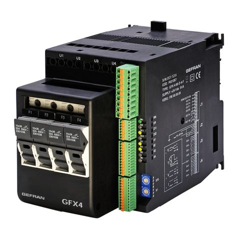
gefran GEFLEX Product manual

GEFLEX Valves
MODULAR POWER CONTROLLER FOR MOTORIZED VALVES
Code 80346B / Edition 0.3 -07/09
OPERATING INSTRUCTIONS
AND WARNINGS
TABLE OF CONTENTS
Page
Graphic symbols used 1
1 Preliminary instructions 2
General description 2
2 Installation and Connection 3
2.1 Overall dimensions and mounting dimensions 4
2.2 Description of base 5
2.3 Installation examples 6
3 Electrical connections 7
3.1 Wire terminal table 7
3.2 Funzionamento relè Geflex “Master” 7
3.3 Connessioni di potenza 7
3.4 Input / Output / Power supply connections 8
3.5 Serial connections 9
3.6 Connection of
Master+Slave modules 10
4 Installation of “MODBUS” serial network 10
4.1 “AUTOBAUD”sequence 11
4.2 “AUTONODE”sequence 11
4.3 “CHANGE”sequence 12
4.4 Software on/off 12
5 Adjustment with motorized valve 13
5.1 Characteristic parameters
for valves control 13
6 Valve control modes 14
7 Automatic calibration of
connected potentiometer 14
8 Manual calibration of valve 14
9 Technical specifications 15
10 Technical-Commercial information 16
10.1 Accessories 17
To distinguish between the type and importance of the
information provided in these instructions for use, graphic
symbols have been used as a reference to make interpreting
the information clearer.
Indicates the contents of the various manual sections, the general
warnings, notes, and other points to which the reader's attention
should be drawn
Indicates a particularly delicate situation that could affect
the safety and correct working operation of the controller,
or a rule that must be strictly observed to avoid dangerous
situations
Indicates a condition of risk for the safety of the user, due to the
presence of dangerous voltages at the points shown
Indicates a suggestion based on the experience of the
GEFRAN Technical Staff, which could prove
especially useful under given circumstances
Indicates a reference to Detailed Technical
Documents available on the GEFRAN web site
www.gefran.com
GRAPHIC SYMBOLS USED
1
80346B_MHW_GFX-VALVOLE_0709_ENG

1 •PRELIMINARY INSTRUCTIONS
This section contains information and warnings
of a general nature which should be read before
proceeding with controller installation,
configuration and use..
General description
Modular controllers GEFRAN series GEFLEX Multifunction
have been designed for temperature control in any applications
involving heating or cooling processes.
They represent an exclusive combination of
performance, reliability and applicational flexibility.
In particular, this new line of Gefran temperature
controllers is the ideal solution for application in sectors where
performance and service continuity are important, including:
extrusion lines
•injection molding for plastic materials
•thermoformers
•presses for rubber
•wrapping and packaging machines
•processing plant for the food industry
•cooling switchboards
•climatic chambers and test benches
•ovens
•paint plants
•etc.
The GEFLEX Multifunction series controllers are made on an
extremely versatile hardware and software platform, that allows
the most suitable I/O composition for the plant to be chosen
from a series of options.
Attention: the programming and configuration
parameters are described in the "Programming and
Configuration" manual enclosed with the Geflex
Master and downloadable from www.gefran.com
Preliminary Warnings
The following preliminary warnings should be read
before installing and using the series GEFLEX
Multifunction controller. This will allow the controller
to be put into service more quickly and will avoid
certain problems which may mistakenly be
interpreted as malfunctions or limitations of the
controller.
•Immediately after unpacking the controller, make a
note of the order code and the other identification
data given on the label affixed to the outside of the
container and copy them to the table below.
These details must always be kept close at hand and
referred to the personnel involved in the event of help
from Gefran Customer Service Assistance.
•Check also that the controller is complete and has
not been damaged at all during transit, and that the
package contains not only the controller and these
Instructions for Use, as well as for the GEFLEX
Multifunction Master model, the "Programming and
Configuration manual”.
Any inconsistencies, omissions or evident signs of
damage should be reported immediately to your
Gefran sales agent.
•Check that the order code corresponds with the
configuration requested for the application the controller is
needed for, referring to Section:
“Technical - Commercial Information”.
Example: GFX-S2 - V/0-0 - D - RR - P - P0
Slave model
Functional module
Rated voltage
Cooling output
Auxiliary outputs
Digital input
Diagnostics
•Before installing the GEFLEX Multifunction temperature
controller in the machine control panel or host system, read
paragraph 2.1 "Overall dimensions and mounting
dimensions”.
•If the instrument is to be configured by PC, make sure you
have the WINSTRUM Kit.
For the order code refer to Section "Technical-Commercial
Information”.
Users and/or system integrators who wish to know
more about the concepts of serial communication
between standard PC and/or Gefran Industrial PC and
Gefran Programmable Instruments, can access the
various technical reference Documents in Adobe
Acrobat format available in the Download section of
the Gefran Web Site www.gefran.com including:
•Serial Communication
•MODBus Protocol
In the event of presumed instrument malfunction, before
contacting Gefran Technical Service Assistance, refer to the
Troubleshooting Guide given in Section 6 "Maintenance", and
if necessary refer to the F.A.Q. Section (Frequently Asked
Questions) on the Gefran Web Site www.gefran.com
SN............................... (Serial Number)
CODE......................... (Product code)
TYPE........................... (Order code)
SUPPLY...................... (Type of electrical power supply)
VERS. ......................... (Firmware Version)
280346B_MHW_GFX-VALVOLE_0709_ENG

This section contains the instructions necessary for
correct installation of the GEFLEX Multifunction
controllers into the machine control panel or the host
system and for correct connection of the controller
power supply, inputs, outputs and interfaces.
Before proceeding with installation read the
following warnings carefully!
Remember that lack of observation of these
warnings could lead to problems of electrical
safety and electromagnetic compatibility, as well
as invalidating the warranty.
Electrical power supply
•the controller is NOT equipped with an On/Off switch:
the user must provide a two-phase disconnecting switch that
conforms to the required safety standards (CE marking), to
cut off the power supply upstream of the controller.
The switch must be located in the immediate vicinity of the
controller and must be within easy reach of the operator.
One switch may control more than one controller.
•if the controller is connected to NOT isolated electrical
equipment (e.g. thermocouples), the earth connection must
be made with a specific conductor to prevent the connection
itself from coming directly through the machine structure.
•if the controller is used in applications with risk of damage to
persons, machinery or materials, it is essential to connect it
up to auxiliary alarm equipment. It is advisable to make sure
that alarm signals are also triggered during normal
operation.
The controller must NOT be installed in flammable or
explosive environments; it may be connected to equipment
operating in such atmospheres only by means of appropriate
and adequate types of interface, conforming to the
applicable safety standards.
Notes Concerning Electrical Safety and
Electromagnetic Compatibility:
•CE MARKING: EMC Conformity (electromagnetic
compatibility)
in accordance with EEC Directive EMC 2004/108/CE.
Series GEFLEX Multifunction controllers are mainly designed
to operate in industrial environments, installed on the
switchboards or control panels of productive process
machines or plants.
As regards electromagnetic compatibility, the strictest generic
standards have been adopted, as indicated in the table
below.
•BT Conformity (low tension)
in accordance with Directive 2006/95/CE.
EMC conformity has been tested with the following connections
(table 1).
Advice for Correct Installation for EMC
Instrument power supply
•The power supply to the electronic equipment on the
switchboards must always come directly from an isolation
device with a fuse for the instrument part.
•The electronic instruments and electromechanical power
devices such as relays, contactors, solenoid valves, etc.,
must always be powered by separate lines.
•When the electronic instrument power supply is strongly
disturbed by the commutation of transistor or power units or
motors, an isolation transformer should be used for the
controllers only, earthing the screen.
•It is essential that the plant has a good earth connection:
- the voltage between neutral and earth must not be > 1V
- the Ohmic resistance must be < 6Ω;
•If the mains voltage fluctuates strongly, use a voltage
stabilizer.
•In the proximity of high frequency generators or arc
welders, use adequate mains filters.
•The power supply lines must be separate from the
instrument input and output ones.
Inputs and outputs connection
•The externally connected circuits must be doubly isolated.
•To connect the analogue inputs (TC, RTD) the following is
necessary:
- physically separate the input cables from those of the power
supply, the outputs and the power connections.
- use woven and screened cables, with the screen earthed
in one point only.
•To connect the regulating and alarm outputs (contactors,
solenoid valves, motors, fans, etc.), fit RC groups
(resistance and condensers in series) in parallel to the
inductive loads that operate in Alternating Current.
(Note: all the condensers must conform to VDE (class X2)
standards and withstand a voltage of at least 220V AC.
The resistances must be at least 2W).
•Fit a 1N4007 diode in parallel with the coil of the inductive
loads that operate in Direct Current.
GEFRAN S.p.A. declines all responsibility for any
damage to persons or property caused by
tampering, neglect, improper use or any use
which does not conform to the characteristics of
the controller and to the indications given in
these Instructions for Use.
2 •INSTALLATION AND CONNECTION
3
80346B_MHW_GFX-VALVOLE_0709_ENG
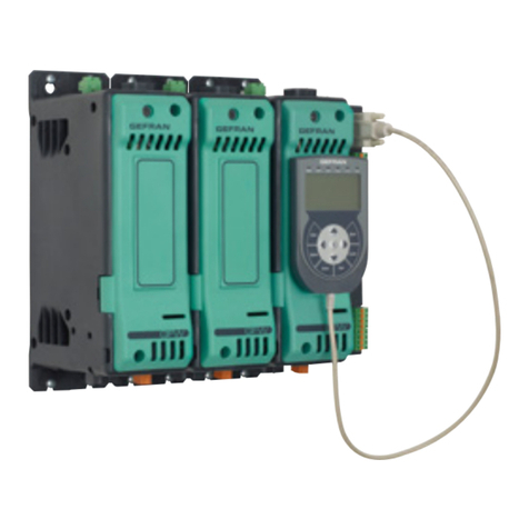
2.1 Overall dimensions and mounting dimensions
1) Position each GEFLEX module with the longer side aligned
with the vertical axis of the electrical panel to increase
adequate natural air flow to the heat sink. The minimum
distance from the side walls of the panel must be 20 mm; from
the top and bottom walls, the minimum distance must be
100mm.
2) If a Master (GFX-M2...), install the module at the extreme
left of the space reserved on the electromechanical plate; line
up the Slave (GFX-S2…) or Expansion (GFX-E2…) modules
progressively to the right of the Master, for a maximum of ten
modules in all (see "Connection Examples").
3) The distance between the modules is shown on the attached
drawing. The minimum distances can be used if the actual
current is less than or equal to 75% of the maximum current
shown on the GEFLEX data plate.
4) Attach each GEFLEX module to the electromechanical plate
by means of DIN EN50022 guide or directly with 5MA screws
(see "Dimensions and Cutout").
5) Remove the screw fastening the wire to the ground terminal,
and then remove the protective cover from the power terminals
by sliding it upward.
6) Wire signal terminal boards "J1" and "J2", connect the
INPUT power terminals to Line, OUTPUT to Load and
COMMON to the return phase of Load (see "Electrical
Connections").
FUNCTION CABLE TYPE LENGTH
Power supply cable 1 mm21 mt
Relay output cables 1 mm23,5 mt
Serial connection wire 0,35 mm23,5 mt
Power connection cable see related sections 3.5 mt
Thermocouple input probe 0,8 mm2compensated 5 mt
“PT100”temperature resistance input probe 1 mm23 mt
EMC conformity has been tested with the following connections
Table 1
Electrical device of measure, control, laboratory, prescription
electromagnetic compatibility
Generic standards, emission standard for residential
commercial and light industrial environments
Emission enclosure
Emission AC mains
Radiated emission
EN 61326-1
EN 61000-6-3
EN 61000-6-3
EN 61000-6-3
EN 61326 CISPR 16-2
Group1 Class B
Group1 Class B
Class B
EMC Emission
EMC Immunity
Generic standards, immunity standard for industrial
environments
Immunity ESD
Immunity RF interference
Immunity conducted disturbance
Immunity burst
Immunity pulse
Immunity Magnetic fields
Voltage dips, short interruptions and voltage immunity tests
EN 61000-6-2
EN 61000-4-2
EN 61000-4-3 /A1
EN 61000-4-6
EN 61000-4-4
EN 61000-4-5
EN 61000-4-8
EN 61000-4-11
4 kV contact discharge level 2
8 kV air discharge
level 3
10 V/m amplitude modulated
80 MHz-1 GHz
10 V/m amplitude modulated
1.4 GHz-2 GHz
10 V/m amplitude modulated
0.15 MHz-
80 MHz (level 3)
2 kV power line (level 3)
2 kV I/O signal line (level 4)
Power line-line 1 kV (level 2)
Power line-earth 2 kV (level 3)
Signal line-earth 1 kV (level 2)
100 A/m (level 5)
100%U, 70%U, 40%U,
LVD Safety
Safety requirements for electrical equipment for measurement,
control and laboratory use EN 61010-1
480346B_MHW_GFX-VALVOLE_0709_ENG

Base
Mounting on electromechanical plate with quick
coupling to DIN EN50022 guide or with 5mA
screws
Base with "Double Relay” module
7) Attach the protective cover of the power terminals and
connect the wire to the ground terminal.
8) If the module is a Master (GFX-M2...), wire its connector to
the serial interface see "Electrical Connections").
9) If the module is a Slave (GFX-S2...) or Expansion (GFX-
E2...), attach the flat wire to the corresponding connector "J3"
of the module immediately to the left (see "Connection
Examples").
Led L2 "Error" LED (red)
Activates when one of the following errors is present:
LO = process variable value is < di Lo.S
HI = process variable value is > di Hi.S
Sbr = broken probe or input values beyond maximum
limits
Err = third wire broken for Pt100, PTC or input values
below minimum limits
(ex.: for CT with incorrect connection)
Led L1 "Status" LED (green)
Freely settable with parameter
197 (Ld.St).
Default setting is16
(RUN flashes)
Connection to previous module
(Slave and Expansion modul only)
J1
Probe and power supply terminal board
Led L3 “Main”(yellow)
Follows trend of
open valve (OUT1)
Fieldbus node selection
J3
Connection to next module
J2
Output terminal board
Fieldbus connection
(Master moduls only)
2.2 Description of base
Connection key to DIN EN50022 guide
J4
Power terminal board
J5
Auxiliary input terminal board
5
80346B_MHW_GFX-VALVOLE_0709_ENG

2.3 Connection examples
220 mm (MIN)
AIR FLOW
300 mm (MIN)
680346B_MHW_GFX-VALVOLE_0709_ENG

3 •ELECTRICAL CONNECTIONS
3.1 Wire terminal table
0,14 - 1,5mm2/ 28-16AWG 0,25 - 0,5mm2/ 24-20AWG
Flexible wire
conductor Conductor with prod terminal
with insulating collar
SIGNAL
0,2 - 2,5mm2/ 24-12AWG 0,25 - 2,5mm2/ 24-12AWGPOWER
Cross-cut screwdriver, blade 0.4 x 2.5mm
Output "OUT3" can function independently of the state of the Geflex Slaves by setting parameter "rL5" to 128 on each Geflex Slave.
•The "OUT4" relay can be energized only with the simultaneous presence of the "rL4" command of the Geflex Master and commands "rL6" of
all the Geflex Slave. This "AND" of alarms among the devices can be used, for example, to signal "minimum temperature setpoint reached" in
each zone to be heated by appropriately configuring the "Ax.r" parameters.
Output "OUT4" can operate independently of the state of the Geflex Slaves by setting parameter "rL6" to 160 (128+32) on each Geflex Slave.
For more information, see the "Configuration and Programming" manual”.
Geflex Master “rL4”Geflex Slave “rL6”Geflex Slave “rL6”Geflex Master “OUT4”
Geflex Master “rL3”
Geflex Slave “rL5”
Geflex Slave “rL5”
Geflex Master “OUT3”
The "OUT3" and "OUT4" relays on the Geflex Master module provide special functions designed to reduce user wiring. These functions are
active even when the Geflex Master module is not powered.
•The "OUT3" relay can be energized by the "rL3" command of the Geflex Master and by the "rL5" command of each Geflex Slave. This "OR"
function of alarms among the devices can be used, for example, for a "maximum temperature setpoint" alarm in each zone to be heated by
appropriately configuring the "Ax.r" parameters.
3.2 Operation of Geflex "Master" relay
3.3 Power connections
J4
L1
PE
N
L3
L2
Double relay module "RR"
1 2 3 4
Open valve (OUT 1): jumper 1-3
Close valve (OUT 7): jumper 2-3
7
80346B_MHW_GFX-VALVOLE_0709_ENG

(Logic output PNP18...32VDC
optional not isolated
from power supply)
18
C2
NA2
C3
NA3
NA1
C1 (+)
(-)
J2
J1
17
J3
L+
T
M
+
-
L+
+
-
+
-
PE
TC Pt100
3 wires LIN INP
Idc (20mA) LIN INP
Vdc (1V)
Digital input
Power supply (18...32Vdc)
OUT 4 (AL2)
OUT 3 (AL1)
OUT 2 (COOL)
1
2
3
4
5
6
7
8
7
5
4
2
1
J1-
J2-
3.4 Input / Output / Power Supply connections
12345
+
-
+
-
+
IN
-
o
PE
Potentiometer
1KΩ...100KΩ
Amplified probe
Voltage 0...10V d.c.
Amplified probe
Current 0...20mA d.c.
J4
J5
J1: Probe and power supply terminal board
J2: Relay output terminal board
J3: Connection among modules
J4: Power terminal board
J5: Aux. input terminal board
880346B_MHW_GFX-VALVOLE_0709_ENG

3.5 Serial connections
“MODBUS”serial
“CANopen”serial
“PROFIBUS DP”serial
D-SUB connector
9-pin Male
D-SUB Connector
9-pin Female
From CANbus network
Shielded cable 2 pairs 22/24 AWG
CANopen conformity
We advise you to connect a 120Ω1/4W resistance between
the "CAN_L" and "CAN_H" signals at both ends of the
CANbus network.
D-SUB Connector
9-pin Male Shielded cable 1 pair 22 AWG
MODBUS conformity
From Modbus network
It is also advisable to connect the "GND" signal between
Modbus devices having a line distance > 100m.
Shielded cable 1 pair 22 AWG
PROFIBUS conformity
From PROFIBUS
network
We advise you to connect a 220Ω1/4W resistance between
the "RxD/TxD-P" and "RxD/TxD-N" signals, a 390Ω1/4W
resistance between the "RxD/TxD-P" and "Vp" signals, and a
390Ω1/4W resistance between the "RxD/TxD-N" and
"DGND" signals at both ends of the Profibus network.
“DeviceNet”serial
V-
CAN_L
SHIELD
CAN_H
V+
1234
5
Connector 5 pin
From DeviceNet network
Shielded cable 2 pairs 22/24 AWG
DeviceNet conformity
We advise you to connect a 120Ω1/4W resistance between
the "CAN_L" and "CAN_H" signals at both ends of the
DeviceNet network.
9
80346B_MHW_GFX-VALVOLE_0709_ENG
TX / RX+
TX / RX-
TX / RX+
TX / RX-
SCH
GND
TX / RX+
TX /
TX / RX-
GND
From previous module
on Modbus network
To next module on
Modbus network
We advise you to connect pins 6 to 7 and pins 8 to 9 on the
connector of the last Geflex on the Modbus network to insert
the line termination.

3.6 Connection of MASTER + SLAVE modules
4. INSTALLATION OF MODBUS SERIAL NETWORK
In a network, there is typically a Master that "manages"
communication by means of "commands" and Slaves that
interpret these commands.
Geflex Masters are to be considered slaves to the network
master, which is usually a supervision terminal or PLC.
In addition, both the Geflex Masters and Slaves are identified in
an unequivocal manner by means of a node address (ID).
The Geflex Master differs from the Geflex Slave only because
the Geflex Master can be connected to the fieldbus.
In addition, the Geflex Master shows the state of the Geflex
Slave on its outputs "OUT4" and "OUT5" by means of the OR
and AND functions:
The Geflex Masters are available (see order code) with one of
the following protocols: ModBus, Profibus or CANopen.
The following procedures are to be considered indispensable
for the ModBus protocol.
For the other protocols, refer to the specific Geflex Profibus and
Geflex CANopen manuals.
GEFLEX modules are supplied preset for 19200 baud without
parity and with rotary selector for node address “0”.
A maximum of ninety GEFLEX modules can be installed in a
serial network, with node address selectable from “10”to “99”.
INSTALLATION
SERIAL NETWORK
?
"AUTOBAUD"
SEQUENCE
?
?
"CHANGE"
SEQUENCE
OPERATIVE
FUNCTION
"AUTONODE"
SEQUENCE
First installation of network Replacement or addition of a module
Slave
Master
YES
NO
Green "STATUS" LED
flashes at 2Hz
Green "STATUS" LED
flashes at 5Hz of
master
Green "STATUS" LED
flashes at 5Hz
Serial network communication
speed is 19200 baud
Green "STATUS" LED
flashes at 10Hz
SETTING THE
NODE
ADDRESS
10 80346B_MHW_GFX-VALVOLE_0709_ENG

4.2 “AUTONODE”sequence
Each GEFLEX module has to be assigned an unequivocal
node address in the serial network.
If the entire network was previously initialized and you want to
add a new module to the network, go directly to the "CHANGE"
sequence. The node address is assigned by means of the
rotary selector on each module.
Geflex Master modules can assume tens values only 1 = 10, 2
= 20, ... 9 = 90.
(ex. Geflex Master rotary selector = 2, node address = 20)
Geflex Slave modules can assume only the values that are the
sum of their own rotary selector (representing units) plus the
tens set on the connected master.
(ex. Geflex Master rotary selector = 2, node address = 20; Geflex
Slave rotary selector = 3, node address = 20+3= 23).
The green "STATUS" LED L1 mentioned in the
procedure can vary its behavior based on parameter
Ld.St , which has a default setting of 16.
The red LED not mentioned in the procedure can
vary its behavior based on the presence of an error
on the main input.
1) Cut power to the Geflex modules.
2) Set the rotary selector on the Slave modules (GFX-S1...) in
progression from "1" to "9".
3) The rotary selector on the Master modules (GFX-M1..) must
be set from "1" to "9".
4)Energize the electrical panel, check that the green
"STATUS" LEDs flash at a frequency of 2Hz. (If parameter 197
Ld.St = 16 as default). In this step, each module has acquired
the status of its rotary selector.
5) Cut power to the Geflex modules.
6) Disconnect the serial cable from each Geflex Master.
7) Turn the rotary selector of the Master module to position "A".
8) Energize the electrical panel.
9) Check that the green "STATUS" LED on the Master module
flash at a frequency of about 5Hz.
10) The procedure is finished when the green "STATUS" LED
and red "ERR" LED flash at a frequency of about 2Hz.
11) Turn the power off.
12) Connect the serial cable to each Geflex Master.
13) Return the rotary selector on the Master module to the
position assigned at point 3.
The new node address parameter is saved permanently in
each Geflex, so you will not have to activate the "AUTONODE"
sequence at future power-ups.
Steps 1, 4, 5, 8 and 11 are necessary only for Geflexes with
firmware 1.0x. In later versions, when the rotary selector is
moved, the green "STATUS" LED remains on
steadily for about 6 seconds, after which it resumes
its normal operation, saving the address.
4.1 “AUTOBAUD”sequence
Adjust the serial communication speed and parity of the Geflex
models to the supervision terminal or PLC.
If network speed is 19200 baud and there is no parity, go
directly to the "AUTONODE" sequence.
The green "STATUS" LED L1 mentioned in the
procedure can vary its behavior based on parameter
Ld.St , which has a default setting of 16.
The red LED not mentioned in the procedure can
vary its behavior based on the presence of an error
on the main input.
1) Cut power to the Geflex modules.
2) Connect the serial cables to all of the Master modules
(GFX-M1…) in the network and to the supervision terminal.
3) Set the rotary selector on the Geflex modules to be installed
(or on all the module in case of a first installation) to “0”.
4) Turn on power to the electrical pane.
5) Check that the green "STATUS" LEDs are flashing at high
frequency (10Hz).
6) The supervision terminal has to transmit a series of generic
"MODBUS" read messages to the network.
7) The procedure is finished when all of the green "STATUS"
LEDs L1 on the Geflex modules flash at a normal frequency
(2 Hz). (If parameter 197 Ld.St = 16 as default.).
The new speed parameter is saved permanently in each
Geflex, so you will not have to activate the "AUTOBAUD"
sequence at future power-ups.
Steps 1 and 4 are necessary only for Geflexes with
firmware 1.0x. In later versions, when the rotary
selector is moved, the green "STATUS" LED
remains on steadily for about 6 seconds, after which
it resumes its normal operation, saving the address.
11
80346B_MHW_GFX-VALVOLE_0709_ENG

This is necessary when replacing a module or adding a new
module to the network in order to assign a correct node
address and communication speed.
For a Master module (GFX-M1...), simply set the rotary selector
to the position you want, then energize the electrical panel.
For a Slave module (GFX-S1...), do as follows.
1) Cut power to the Geflex modules.
2) Disconnect the serial cable from the Geflex Master.
3) Turn the rotary selector of the Slave to be inserted to
position “0”.
4) Turn the rotary selector of the Master to position “A”.
5) Turn on power to the Geflex modules.
6) Check that the green "STATUS" LED of the Slave is flashing
at high frequency (10 Hz).
7) Check that the green "STATUS" LED of the Master is
flashing at medium frequency (5Hz).
8) During this phase, the new module learns the speed and
address (decimal part).
9) The procedure is finished when all of the green "STATUS"
LEDs flash at a normal frequency (2 Hz).
10) Cut power to the Geflex modules.
11) Connect the serial cable to the Geflex Master module.
12) Return the rotary selector on the Geflex Master to the
position assigned at point.
The new node address parameter is saved permanently in
each Geflex, so you will not have to activate the "AUTONODE"
sequence at future power-ups.
Steps 1, 4, 5, 8 and 11 are necessary only for
Geflexes with firmware 1.0x. In later versions, when
the rotary selector is moved, the green "STATUS"
LED remains on steadily for about 6 seconds, after
which it resumes its normal operation, saving the
address.
4.3 “CHANGE”sequence
4.4 Software On/Off
This function is obtained with the digital input if configured (diG
= 6).).
All outputs (control and alarms) are OFF (logic level 0, relays
de-energized) and all the instrument control functions are
inhibited except for "ON" function and serial dialog.
The PV input continues to be sampled
If software on/off is performed, you will have the following
consequences:
1) Reset Auto-tuning, Self-tuning and Soft-start functions
2) Digital input (if present) enabled only if linked to SW
shutdown function
3) In case of restart after SW shutdown, the ramp linked to the
set starts from the PV
4) Outputs OFF: except for OUT4 (Master) and OUT6 (Slave)
of the Geflex instrument, which are forced ON
5) Reset HB alarm
6) Reset LBA alarm
7) In case of Geflex, Heat and Cool bit of status word
STATUS_ST_RAM and POWER are reset.
8) The current power level is saved when the instrument is
switched off. When it is switched on again, integral power is
calculated as the difference between saved power and
proportional power. This calculation is defined as “desaturation
at switch-on”.
12 80346B_MHW_GFX-VALVOLE_0709_ENG

The controller determines, on the basis of the dynamics of the
process, the control output for the valve corresponding to the
opening of the same in such a way so as to maintain the
desired value of the process variable.
With counter-reaction valves the position is normally provided
by a potentiometer assembled on the actuator.
5 •ADJUSTMENT WITH MOTORIZED VALVE
Adjustment valve
Actuator
SetPoint
Process
M
CONTROL EXAMPLE FOR V0 VALVE VALVE POSITION CONTROL
Control
Motor
Adjustment valve
Desired position
Process
variable Valve position
feedback
potentiometer
In an adjustment process the adjustment valve has the
function of varying fuel delivery (frequently corresponding to
the thermal energy introduced into the process) in relation to
the signal coming from the controller.
For this purpose it is provided with an actuator able to modify
its opening value, overcoming the resistances produced by
the fluid passing inside it.
The adjustment valves vary the delivery in a modulated
manner, producing finite variations in the fluid passage inner
area corresponding to finite variations of the actuator input
signal, coming from the controller. The servomechanism, for
example, comprises an electric motor, a reducer and a
mechanical transmission system which actions the valve.
Various auxiliary components can be present such as the
mechanical and electrical safety end travels, manual actioning
systems, position location.
5.1 Characteristic parameters for valves control
- Actuator time (_At_) is the time employed by the valve to
pass from entirely open to entirely closed (or vice-versa), and
can be set with a resolution of one second.
It is a mechanical feature of the valve+actuator unit.
NOTE: if the actuator’s travel is mechanically limited it is
necessary to proportionally reduce the _At_ value.
- Minimum impulse (t_Lo) expressed as a % of the actuator
time (resolution 0.1%).
Represents the minimum change in position corresponding to
a minimum change in power supplied by the instrument below
which the actuator will not physically respond to the
command.
This represents the minimum variation in position due to
which the actuator does not physically respond to the
command.
The minimum duration of the movement can be set in t.on,
expressed as a % of actuator time.
- Impulsive intervention threshold (t_Hi) expressed as a % of
the actuator time (resolution 0.1%) represents the position
displacement (requested position –real position) due to which
the manoeuvre request becomes impulsive.
You can choose between 2 types of control:
1) ON time of movement = t.on and OFF time proportional to
shift and greater than or equal to t_Lo (we recommend setting
t.on = t.Lo) (set t.off = 0).
2) ON time of movement = t.on and OFF time = t.off. A value
set for t.off < t.on is forced to t.on. To activate this type, set
t.off < > 0.
The type of movement approach allows fine control of the
reverse drive valve (from potentiometer or not), especially
useful in cases of high mechanical inertia.
Set t_Hi = 0 to exclude modulation in positioning.
This type of modulated approach allows precise control of the
feedback actioned valve, by a potentiometer or not, and is
especially useful in cases of high mechanical inertia. Setting
t_Hi = 0 excludes modulation in positioning.
- Dead zone(_db_) is a displacement band between the
adjustment setpoint and the process variable within which the
controller does not supply any command to the valve (Open =
OFF; Close = OFF).
It is expressed as a percentage of the bottom scale and is
symmetrical with respect to the setpoint.
The dead zone is useful in an operative process to avoid
straining the actuator with repeated commands and an
insignificant effect on the adjustment. Setting _db_ = 0 the
dead zone is excluded.
t_Hi
t_Lo t_Lo t_Lo
t0 t1 t2 Graph of behavior inside the band with integral
time ¤0.
With integral time = 0, movement ON time is
always equal to OFF time.
t0 = t_Lo
13
80346B_MHW_GFX-VALVOLE_0709_ENG
6 •VALVE CONTROL MODES
With the controller in manual, the setting of parameter At.ty ≥8
allows direct control of the valve open and close commands;
the instrument indicates the presumed or real position (for type
V2):
V0 - for floating valve without potentiometer;
V2 - for valve with feedback from potentiometer.
Model V0 have similar behaviour: every manoeuvre request
greater than the minimum impulse t_Lo is sent to the actuator
by means of the OPEN/CLOSE relays; every action updates
the presumed position of the virtual potentiometer calculated
on the basis of the actuator travel declared time.
In this way there is always a presumed position of the valve
which is compared with the position request of the controller.
Having reached a presumed extreme position (entirely open or
entirely closed determined by the “virtual potentiometer”) the
controller provides a command in the same direction, in this
way ensuring the real extreme position is reached (minimum
command time = t.on).
The actuators are usually protected against the OPEN
command in the entirely open position or CLOSE command in
the entirely closed position.
The V2 model reads the real position of the valve by means of
the auxiliary analogue input, expresses the value as a
percentage (0.0 –100.0%) and compares it with the position
requested by the controller, then sends the appropriate
command to the valve.
The auxiliary input of the controller is used to obtain the valve
position.
Calibration is requested to memorise the extreme position of
the potentiometer, minimum and maximum.
The potentiometer is usually supplied by the controller itself
V3 - for floating valve, PI control
When the difference between the position calculated by the
controller and the only proportional component exceeds the
value corresponding to the minimum impulse t_Lo the
controller provides an OPEN or CLOSE command of the
duration of the minimum impulse itself t_Lo.
At each delivery the integral component of the command is set
to zero (discharge of the integral).
The frequency and duration of the impulses is correlated to the
integral time (_ti_).
Non-movement behavior
t_Hi = 0: with power = 100% or 0.0%, the corresponding open
or close outputs always remain enabled (safety status).
Movement behavior
t_Hi < > 0: with position attained corresponding to 100% or
0.0%, the corresponding open or close outputs are switched
off.
t_Hi
t.on t.on t.on
t.off t.off t.off
If t.off = 0, current function is
maintained.
If t.off ¤0 movement mode
will be as shown on the graph
7 •AUTOMATIC CALIBRATION OF CONNECTED POTENTIOMETER
1) Enable virtual keyboard
[191] Hd.1 = 2
[224] S.In = bit 5 = 1
[345] Status6_W = bit 7 = 1
2) Minimum value
[311] Page = 31
[312] Row = 0
Minimum procedure
Set the potentiometer in minimum position by activating the
close output (OUT 7), setting bit 1 = 1 di [320] NEW TAST.
When the position is reached, reset bit 1 = 0 of [320] NEW
TAST.
Confirm the minimum calibration by setting bit 0 = 1 of [320]
NEW TAST and resetting within 0.5 sec.
Maximum procedure
Set the potentiometer in maximum position by activating the
open output (OUT 1), setting bit 3 = 1 of [320] NEW TAST.
When the position is reached, reset bit 3 = 0 of [320] NEW
TAST.
Confirm the maximum calibration by setting bit 0 = 1 of [320]
NEW TAST and resetting within 0.5 sec.
8 •MANUAL CALIBRATION OF VALVE
Enable virtual keyboard
[191] Hd.1 = 2
[224] S.In = bit 5 = 1
[345] Status6_W = bit 7
Set bit 1 = 1 of [320] NEW TAST to command the close
output (OUT 7).
Set bit 3 = 1 of [320] NEW TAST to command the open output
(OUT 1).
14 80346B_MHW_GFX-VALVOLE_0709_ENG
8 •TECHNICAL SPECIFICATIONS
Inputs Accuracy main input
Thermal drift
Main input
(configurable digital filter)
Type TC (Thermocouples) (ITS90)
Cold junction error
RTD type (scale settable in indicated range,
with/without decimal point) (ITS90)
Max. line resistance for RTD
Accuracy auxiliary input
Auxiliary input
Logic input
Functionality Safety
°C/°F selection
Linear scale ranges
Controls
pb - dt - it
Action - Control outputs
Max. power limit heat / cool
Cycle time - Softstart
Fault power setting
Automatic blanking
Configurable alarms
Alarm masking
Outputs Relay (OUT 2, 3, 4)
Logic (OUT 2)
Continuous (OUT 2)
Functional modules
“RR”double relays
Power supply Power supply
Power supply for amplified probe
Serial Serial interface
Baude rate
Protocol for Geflex master
Optional field bus protocols
General characteristics Indications
Protection
Working / storage temperature range
Relative humidity
Installation
Weight max
0,2% f.s. ±1 scale points at 25°C ambient temperature
0,005% f.s. / °C
TC, RTD 60mV,1V Ri≥1MΩ; 20mA Ri=50Ω
Sampling time 120 msec.
J, K, R, S, T, (IEC 584-1, CEI EN 60584-1, 60584-2)
a custom linearization can be inserted
0,1°/ °C
DIN 43760 (Pt100), JPT100
20Ω
0,2% f.s. ±1 scale points at 25°C ambient temperature
- Potentiometer ≥1KΩ- 0/2...10V (Ri >100K)
- 0/4...20mA (Ri >50Ω)
Sampling time 240msec
24V, 8mA
Detection of short circuit or opening of probes, LBA alarm, HB alarm
Configurable
-1999...9999
Pid, Autotune, on-off
0,0...999,9 % - 0,00...99,99 min - 0,00...99,99 min
heat / cool - on / off, PWM, GTT
0,0...100,0 %
0...200 sec - 0,0...500,0 min
-100,0...100,0 %
Maintains sampling of process variable PV; when active, disables the control
Up to 4 alarm functions assignable to an output and configurable of type: maximum, minimum,
symmetrical, absolute/relative, LBA, HB
Exclusion during warm up memory, reset from digital input
NO, 3A, 250V cosϕ=1
24Vdc, 35mA
0/2...10V, 0/4...20mA at 500Ωmax.
NO, 3A 250V cosϕ=1 unico comune
24Vdc ±25%, 5W max.
+24Vac ± 25% 40mA max.
RS485, optoisolated
1200, 2400, 4800, 9600, 19200
MODBUS RTU
CANopen 10K...1Mbit/sec PROFIBUS DP 9,6...12Mbit/sec
3 LEDs (diagnostics)
IP20
0...40°C / -20...70°C
20...85% Ur non condensing
Barra DIN EN50022 or panel from 5MA screws
600gr
15
80346B_MHW_GFX-VALVOLE_0709_ENG
GEFRAN spa reserves the right to make aesthetic or functional changes at any time and without notice.
This section contains information on the order codes
for the Controller and on main accessories.
As specified in the Preliminary Warnings of these Operating
Instructions, correct interpretation of the Controller order code
permits immediate identification the controller's hardware
configuration. It is therefore essential to give the order code
each time you have to contact Gefran's Customer Care Service
to solve any problems.
9 •TECHNICAL-COMMERCIAL INFORMATION
FUNCTIONAL MODULE
0GFX-M2
DIAGNOSTIC
DIGITAL INPUT
PNP Digital InputP
2 RelaysRR
AUXILIARY OUTPUTS
P
Master Valve RR
Without functional module B_V
With double relays modul V
None0
Multifunction input
0/4...20mA, (0...10V)
IM
Potentiometer inputPO
B_V M0 0
COOLING OUTPUT
Absent
Logic
0
D
Relays R
Continuous output 0...10V
(0/4...20mA) C
FUNCTIONAL MODULE
0GFX-S2
DIAGNOSTIC
DIGITAL INPUT
PNP Digital InputP
Absent0
AUXILIARY OUTPUTS
P
Slave Valve 00
Without functional module B_V
With double relays modul V
None0
Multifunction input
0/4...20mA, (0...10V)
IM
Potentiometer inputPO
B_V 00 0
COOLING OUTPUT
Absent
Logic
0
D
Relays R
Continuous output 0...10V
(0/4...20mA) C
2 RelaysRR
SERIAL COMMUNICATION
MODBUS RTU
PROFIBUS DP
M
P
CANopen C
DeviceNet D
16 80346B_MHW_GFX-VALVOLE_0709_ENG
10.1 Accessories
Software for management / configuration of Geflex units.
The main parameters of all Geflex models can be varied with a simple, intuitive interface.
ORDER CODE
Winstrum software on CD, RS232/485 converter complete
with cables to connect the PC and the Geflex . . . . . . . . . . . . . . . . . . . . .WSK - 1 - 1 - 0
Winstrum software on CD, IRDA interface for Geflex . . . . . . . . . . . . . . .WSK - 1 - 2 - 0
[Note: the PC used must be equipped with an IRDA (infrared) interface]
KIT WINSTRUM
Operator terminal for field configuration of the entire Geflex range
Two types of terminals are available:
- for installation on the Geflex heatsink or on DIN guide
- for installation on the faceplate
Programming terminal for Geflex (installation on DIN guide or on heatsink),
complete with connection cable to Geflex (L = 0.2 m) . . . . . . . . . . . . . . . . . . .GFX-OP-D
Note: see cable section for other cable lengths
Programming terminal for Geflex (installation on faceplate) . . . . . . . . . . . . . . .GFX-OP-P
Note: see cable section for connection cable
Kit consists of:
power supply, connection cable PC <--> GFX-DP-D (L = 2 m),
power adapter for the Geflex . . . . . . . . . . . . . . . . . . . . . . . . . . . . . . . . . . . . . .GFX-OP-K
GFX-OP
ORDER CODE
Series of modules insertable on base
Double relay module . . . . . . . . . . . . . . . . . . . . . . . . . . . . . . . . . . . . . . . . .GFX-OUT-RR
MODULES
ORDER CODE
Note: See the Geflex catalog for more accessories.
17
80346B_MHW_GFX-VALVOLE_0709_ENG
Table of contents
Other gefran Control Unit manuals

gefran
gefran R-MA6 User manual

gefran
gefran R-E16 User manual

gefran
gefran R-GCANs User manual

gefran
gefran GTS-T 10 Series Instruction manual

gefran
gefran R-MIX User manual

gefran
gefran EXP-DN-BDI-VDI User manual

gefran
gefran SIEIDrive E-ABS User manual

gefran
gefran R-D/A4 User manual

gefran
gefran GFX4-ETHERNET User manual

gefran
gefran R-TC8 User manual
Popular Control Unit manuals by other brands

T&S
T&S B-0107 Installation and maintenance instructions

Maco
Maco HAUTAU WLAN-Box Installation and operating instructions

Genesis
Genesis SOS-5 quick guide

Fire-Lite Alarms
Fire-Lite Alarms BG-12LR operating instructions

Frequency Central
Frequency Central Continuum Phase Shifter Build documentation

Texas Instruments
Texas Instruments DAC8811 manual