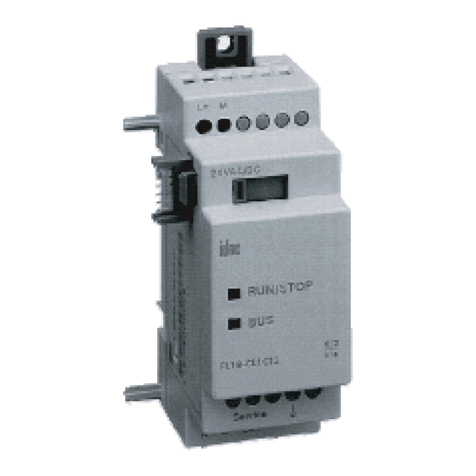
IDEC SmartRelay FL1D Series User manual

Courtesy of Steven Engineering, Inc. ● 230 Ryan Way, South San Francisco, CA 94080-6370 ● General Inquiries: (800) 670-4183 ● www.stevenengineering.com

IDEC SmartRelay Manual i
Preface
Dear customer
We thank you for purchasing IDEC SmartRelay and congrat-
ulate you on your decision.
IDEC SmartRelay can be used in many fields of applications.
Due to its high functionality and yet easy operation the IDEC
SmartRelay offers you utmost efficiency for almost any ap-
plication.
Purpose of this manual
This IDEC SmartRelay manual provides you with information
about the creation of circuit programs, about the installation
and use of IDEC SmartRelay FL1D devices and expansion
modules, and about their compatibility to the previous FL1A
to FL1C versions (FL1x are the last four characters of the
type number and differentiate the device series).
IDEC SmartRelay's place in information technology
The wiring information in your IDEC SmartRelay manual is
also found in the IDEC SmartRelay Product Info included
with all devices. For further information on programming the
IDEC SmartRelay on your PC, refer to the Online Help for
WindLGC.
WindLGC is the programming software for PCs. It runs un-
der Windows®and helps you to get started with IDEC
SmartRelay and to write, test, print out and archive your
programs, independent of the IDEC SmartRelay.
Guide
We have divided this manual into 9 chapters:
•Getting started with IDEC SmartRelay
•IDEC SmartRelay installation and wiring
•Programming IDEC SmartRelay
•IDEC SmartRelay functions
•Configuring IDEC SmartRelay
•IDEC SmartRelay memory cartridge (card)
•IDEC SmartRelay software
•Applications
• Appendix
Courtesy of Steven Engineering, Inc. ● 230 Ryan Way, South San Francisco, CA 94080-6370 ● General Inquiries: (800) 670-4183 ● www.stevenengineering.com

Preface
ii IDEC SmartRelay Manual
Valid range of this manual
The manual applies to devices of the series FL1D.
Changes compared to previous releases of the manual
• The analog module IDEC SmartRelay FL1D-K2B2 was
added.
• The communication module FL1B-CAS2 was added.
• Description of changes and new features of the series
FL1D devices.
Main differences compared to previous devices (FL1A to FL1C)
• Display contrast may be changed.
• Default setting for the start screen may be changed.
• Analog output values for RUN/STOP transition may be
selected.
• Analog inputs and analog outputs have been added to
the RUN mode display.
New features of the current devices (FL1D)
• The “Analog Ramp Control” special function enables you
to use a two-step speed control.
• The “Analog multiplexer” special function enables you to
select 1 of 4 analog values to be output.
• The “PI controller” special function enables you to use a
PI controller function.
Additional support
At our Internet address
http://smart.idec.com/
you can quickly and easily find answers to your queries
about IDEC SmartRelay.
Courtesy of Steven Engineering, Inc. ● 230 Ryan Way, South San Francisco, CA 94080-6370 ● General Inquiries: (800) 670-4183 ● www.stevenengineering.com

Preface
IDEC SmartRelay Manual iii
Safety guidelines
The notes in this user manual are for your own personal
safety and for preventing damage to assets. You should
read them carefully and follow the instructions they give you.
These notes are highlighted with a warning triangle and are
shown according to the degree of hazard as follows:
Qualified personnel
Only skilled personnel should be allowed to start and oper-
ate this device. Qualified personnel in the sense of the infor-
mation on safety technology in this manual are persons who
are authorized to commission, to ground and to tag circuits,
equipment and systems in accordance with safety regula-
tions and standards.
!Danger
Warns that death, serious harm to health or damage to assets will
result if the respective precautionary measures are not taken.
!Warning
Warns that death, serious harm to health or damage can result if
the respective precautionary measures are not taken.
!Caution
Warns that harm to health or damage to assets can result if the re-
spective precautionary measures are not taken.
Caution
Means that material damage may occur if corresponding safety
measures are not taken.
Note
Draws your attention to particularly important information relating
to the product and its handling, or to a part of the documentation
requiring your special attention.
Courtesy of Steven Engineering, Inc. ● 230 Ryan Way, South San Francisco, CA 94080-6370 ● General Inquiries: (800) 670-4183 ● www.stevenengineering.com

Preface
iv IDEC SmartRelay Manual
Use as intended
Please note:
Copyright ©IDEC CORPORATION All rights reserved
The reproduction, distribution or use of this document or its
contents is not permitted without express written authority.
Offenders will be liable for damages. All rights reserved, in
particular in the event of patents being granted or the regis-
tration of a utility model or design.
Disclaimer of liability
We have examined the contents of this publication for agree-
ment with the hardware and software described. Neverthe-
less, discrepancies can not be ruled out. Any liability and
warranty for the accuracy of this information is excluded. The
data in this manual are reviewed at regular intervals. Any
corrections required are included in the subsequent editions.
Suggestions for improvement are welcomed.
!Warning
This device must always be used as intended for the applications
described in the catalog and in the technical specifications, and
only in combination with third-party devices or components ap-
proved or recommended by IDEC.
Prerequisite for the safe and proper operation of the product is its
proper transportation, storage, installation and mounting, and care-
ful operator control and maintenance.
Courtesy of Steven Engineering, Inc. ● 230 Ryan Way, South San Francisco, CA 94080-6370 ● General Inquiries: (800) 670-4183 ● www.stevenengineering.com

IDEC SmartRelay Manual v
Contents
Preface.............................................................. i
1 Getting started with IDEC SmartRelay ......... 1
2 IDEC SmartRelay installation and wiring ... 13
2.1 Modular IDEC SmartRelay setup ........................................ 17
2.1.1 Maximum setup .................................................................. 17
2.1.2 Setup with different voltage classes.................................... 18
2.2 Installing/removing IDEC SmartRelay ............................... 19
2.2.1 DIN rail mounting ................................................................ 20
2.2.2 Wall-mounting..................................................................... 24
2.3 Wiring IDEC SmartRelay ..................................................... 26
2.3.1 Connecting the power supply ............................................. 27
2.3.2 Connecting IDEC SmartRelay inputs.................................. 29
2.3.3 Connecting outputs............................................................. 40
2.3.4 Connecting the AS interface bus ........................................ 44
2.4 Putting into operation ......................................................... 46
2.4.1 Switching on the IDEC SmartRelay/Power On ................... 46
2.4.2 Operating states ................................................................. 50
3 Programming IDEC SmartRelay.................. 52
3.1 Connectors........................................................................... 54
3.2 Blocks and block numbers ................................................. 57
3.3 The way to IDEC SmartRelay, starting with the circuit
diagram................................................................................. 60
3.4 The four golden rules for operating IDEC SmartRelay .... 63
3.5 Overview of IDEC SmartRelay menus ............................... 65
3.6 Writing and starting the circuit program ........................... 66
3.6.1 Select programming mode.................................................. 66
3.6.2 The first circuit program ...................................................... 68
3.6.3 Circuit program input .......................................................... 69
3.6.4 Assigning a circuit program name ...................................... 75
Courtesy of Steven Engineering, Inc. ● 230 Ryan Way, South San Francisco, CA 94080-6370 ● General Inquiries: (800) 670-4183 ● www.stevenengineering.com

vi IDEC SmartRelay Manual
3.6.5 Password ............................................................................ 76
3.6.6 Switching IDEC SmartRelay to RUN mode ........................ 81
3.6.7 Second circuit program ....................................................... 84
3.6.8 Deleting a block .................................................................. 91
3.6.9 Deleting block groups ......................................................... 92
3.6.10 Correcting programming errors........................................... 93
3.6.11 Selecting analog output values for RUN/STOP transition... 93
3.6.12 Deleting the circuit program ................................................ 95
3.6.13 Summertime/wintertime conversion.................................... 96
3.6.14 Synchronization ................................................................ 101
3.7 Memory space and circuit dimensions............................ 102
4 IDEC SmartRelay functions........................108
4.1 Constants and connectors - Co........................................ 109
4.2 Basic functions list - GF.................................................... 112
4.2.1 AND .................................................................................. 114
4.2.2 AND with Edge Detection ................................................. 115
4.2.3 NAND (not AND)............................................................... 116
4.2.4 NAND with Edge Detection............................................... 117
4.2.5 OR .................................................................................... 118
4.2.6 NOR (not OR) ................................................................... 119
4.2.7 XOR (exclusive OR).......................................................... 120
4.2.8 NOT (Negation, Inverter) .................................................. 120
4.3 Basics on special functions.............................................. 121
4.3.1 Designation of the inputs .................................................. 122
4.3.2 Time response .................................................................. 123
4.3.3 Backup of the real-time clock............................................ 124
4.3.4 Retentivity ......................................................................... 124
4.3.5 Parameter protection ........................................................ 124
4.3.6 Calculating the gain and offset of analog values .............. 125
4.4 Special functions list - SF ................................................. 128
4.4.1 On-delay ........................................................................... 132
4.4.2 Off-delay ........................................................................... 136
4.4.3 On-/Off-delay .................................................................... 138
4.4.4 Retentive on-delay ............................................................ 140
4.4.5 Interval time-delay relay / Pulse output ............................ 142
4.4.6 Edge-triggered interval time-delay relay ........................... 144
Courtesy of Steven Engineering, Inc. ● 230 Ryan Way, South San Francisco, CA 94080-6370 ● General Inquiries: (800) 670-4183 ● www.stevenengineering.com

IDEC SmartRelay Manual vii
4.4.7 Asynchronous pulse generator ......................................... 147
4.4.8 Random generator............................................................ 149
4.4.9 Stairwell Light Switch ........................................................ 151
4.4.10 Dual-function switch.......................................................... 154
4.4.11 Seven-day time switch...................................................... 157
4.4.12 Twelve-month time switch................................................. 162
4.4.13 Up/down counter............................................................... 165
4.4.14 Operating hours counter ................................................... 169
4.4.15 Frequency trigger.............................................................. 174
4.4.16 Analog trigger ................................................................... 177
4.4.17 Analog differential trigger.................................................. 180
4.4.18 Analog comparator ........................................................... 184
4.4.19 Analog value monitoring ................................................... 189
4.4.20 Analog amplifier ................................................................ 192
4.4.21 Latching relay ................................................................... 195
4.4.22 Current impulse relay........................................................ 196
4.4.23 Message texts................................................................... 199
4.4.24 Softkey.............................................................................. 206
4.4.25 Shift register...................................................................... 210
4.4.26 Analog multiplexer ............................................................ 213
4.4.27 Analog Ramp Control ....................................................... 217
4.4.28 PI controller....................................................................... 222
5 Configuring IDEC SmartRelay................... 229
5.1 Selecting parameter assignment mode ........................... 230
5.1.1 Parameters ....................................................................... 232
5.1.2 Selecting the parameters.................................................. 233
5.1.3 Modifying parameters ....................................................... 234
5.2 Setting the default values for IDEC SmartRelay ............. 237
5.2.1 Setting the time-of-day and date (FL1D-H12RC...) .......... 237
5.2.2 Setting the display contrast............................................... 239
5.2.3 Setting the start screen..................................................... 240
6
IDEC SmartRelay memory cartridge (card) ..241
6.1 Security function (CopyProtect)....................................... 243
6.2 Inserting and removing the memory cartridge (card) .... 246
Courtesy of Steven Engineering, Inc. ● 230 Ryan Way, South San Francisco, CA 94080-6370 ● General Inquiries: (800) 670-4183 ● www.stevenengineering.com

viii IDEC SmartRelay Manual
6.3 Copying data from the IDEC SmartRelay to the memory
cartridge (card)................................................................... 248
6.4 Copying data from the memory cartridge (card) to IDEC
SmartRelay ......................................................................... 250
7 IDEC SmartRelay software .........................252
7.1 Connecting IDEC SmartRelay to a PC ............................. 255
8 Applications.................................................257
8.1 Stairway or corridor lighting............................................. 259
8.1.1 Requirements for a stairway lighting system .................... 259
8.1.2 Previous solution............................................................... 259
8.1.3 Lighting system with IDEC SmartRelay ............................ 260
8.1.4 Special features and expansion options ........................... 262
8.2 Automatic door .................................................................. 263
8.2.1 Requirements of an automatic door.................................. 263
8.2.2 Conventional solution........................................................ 264
8.2.3 Door control system with IDEC SmartRelay ..................... 264
8.2.4 Special features and expansion options ........................... 267
8.2.5 Extended solution with FL1D-H12RCC............................. 267
8.3 Air-conditioning system.................................................... 270
8.3.1 Requirements for an air-conditioning system.................... 270
8.3.2 Advantages of using IDEC SmartRelay ............................ 273
8.4 Factory door ....................................................................... 275
8.4.1 Requirements for a gate control system ........................... 275
8.4.2 Previous solution............................................................... 276
8.4.3 Extended IDEC SmartRelay solution ................................ 278
8.5 Centralized control and monitoring of several factory
doors ................................................................................... 279
8.5.1 Requirements for a gate control system ........................... 280
8.6 Luminous rows .................................................................. 283
8.6.1 Requirements for a lighting system................................... 283
8.6.2 Previous solution............................................................... 284
8.6.3 Luminous row control system with FL1D-H12RCC........... 285
8.7 Service water pump ........................................................... 287
Courtesy of Steven Engineering, Inc. ● 230 Ryan Way, South San Francisco, CA 94080-6370 ● General Inquiries: (800) 670-4183 ● www.stevenengineering.com

IDEC SmartRelay Manual ix
8.7.1 Requirements for a control system of a service water
pump................................................................................. 288
8.7.2 Previous solution .............................................................. 288
8.7.3 Service water pump system with FL1D-H12RCC............. 289
8.7.4 Special features and expansions ...................................... 290
8.8 Benefits of IDEC SmartRelay ............................................ 291
A Technical data............................................. 293
A.1 General technical data ...................................................... 293
A.2 Technical data: FL1D-H12RCC/FL1D-B12RCC and
FL1B-M08C2R2 .................................................................. 295
A.3 Technical data: FL1D-H12SND and FL1B-M08B1S2....... 298
A.4 Technical data: FL1D-H12RCA/FL1D-B12RCA and
FL1B-M08D2R2 .................................................................. 301
A.5 Technical data: FL1D-H12RCE/FL1D-B12RCE and
FL1B-M08B2R2 .................................................................. 304
A.6 Switching capacity and service life of the relay outputs308
A.7 Technical data: FL1B-J2B2............................................... 309
A.8 Technical data: FL1D-K2B2 .............................................. 310
B Determining the cycle time........................ 311
C IDEC SmartRelay without display ........... 313
D IDEC SmartRelay menu structure ............. 316
E Type Numbers............................................. 318
Index ............................................................ 320
Courtesy of Steven Engineering, Inc. ● 230 Ryan Way, South San Francisco, CA 94080-6370 ● General Inquiries: (800) 670-4183 ● www.stevenengineering.com

1IDEC SmartRelay Manual
1 Getting started with IDEC
SmartRelay
Here's IDEC SmartRelay
IDEC SmartRelay is a universal logic module made by IDEC.
IDEC SmartRelay integrates
• Controls
• Operator and display panel with background lighting
• Power supply
• Interface for expansion modules
• Interface for the memory cartridge (card) and a PC cable
• Pre-configured standard functions, e.g. on- and off-de-
lays, current impulse relay and softkey.
•Timers
• Inputs, Outputs, Memory Markers
What IDEC SmartRelay can do for you
IDEC SmartRelay offers solutions for installation engineer-
ing (e.g. for stairway lighting, external lighting, sun blinds,
shutters, shop window lighting etc.), switch cabinet engi-
neering, as well as for mechanical and apparatus engineer-
ing (e.g. for gate control systems, air-conditioning systems,
or rainwater pumps etc.).
IDEC SmartRelay can also be implemented for special con-
trol systems in conservatories or greenhouses, for control
signal processing and, by connecting a communication mod-
ule (e.g.AS-Interface) for distributed local controlling of ma-
chines and processes.
Special versions without operator panel and display unit are
available for series production applications in small machine,
apparatus, switching cabinet and installation engineering.
Which devices are available?
IDEC SmartRelay Base is available in two voltage classes:
• Class 1 ≤24 V, i.e. 12V DC, 24V DC, 24V AC
Class 2 > 24 V, i.e. 100...240V AC/DC,
in the versions:
•With display: 8 inputs and 4 outputs.
•Without display ("IDEC SmartRelay Pure"): 8 inputs and
4 outputs.
Courtesy of Steven Engineering, Inc. ● 230 Ryan Way, South San Francisco, CA 94080-6370 ● General Inquiries: (800) 670-4183 ● www.stevenengineering.com

Getting started with IDEC SmartRelay
IDEC SmartRelay Manual 2
Each version is integrated into 4 subunits (SU), is equipped
with an expansion interface and provides 36 pre-configured
standard and special function blocks for the creation of your
circuit program.
Which expansion modules are available?
• IDEC SmartRelay digital modules are available for oper-
ation with 12V DC, 24V AC/DC and 100...240V AC/DC,
and are equipped with four inputs and four outputs.
• IDEC SmartRelay analog modules are available for oper-
ation with 24 V DC and with 12 V DC, and are equipped
with two analog inputs or two analog outputs.
The digital/analog modules are integrated in two subunits.
Each one is equipped with two expansion interfaces for con-
necting additional modules.
Which communication modules are available?
• IDEC SmartRelay communication module FL1B-CAS2,
which is described in more detail in a separate documen-
tation.
The communication module has four virtual inputs and
outputs, and acts as an interface between an AS-Inter-
face system and an IDEC SmartRelay system. The mod-
ule enables four data bits to be transferred from the IDEC
SmartRelay Base to the AS-Interface system and vice
versa.
Courtesy of Steven Engineering, Inc. ● 230 Ryan Way, South San Francisco, CA 94080-6370 ● General Inquiries: (800) 670-4183 ● www.stevenengineering.com

Getting started with IDEC SmartRelay
3IDEC SmartRelay Manual
It's your choice
The various IDEC SmartRelay Base versions and expansion
modules and communication modules offer you a highly flex-
ible and adaptive system to suit your specific tasks.
The IDEC SmartRelay system offers you many solutions
such as for simple automation tasks and even complex en-
gineering tasks involving its integration into a bus system
(e.g. communications module AS-interface.)
Note
IDEC SmartRelay Base may only be equipped with expansion mod-
ules of the same voltage class. Mechanical encoding pins in the
housing prevent you from connecting devices of a different voltage
class.
Exception: The left-hand interface of an analog module or commu-
nication module is galvanically isolated. This type of expansion
module can therefore be connected to devices of a different voltage
class. See also Chapter 2.1.
Each IDEC SmartRelay Base provides the following connections
for the creation of the circuit program, regardless of the number of
connected modules:
• Inputs I1 to I24
• Analog inputs AI1 to AI8
• Outputs Q1 to Q16
• Analog outputs AQ1 and AQ2
• Memory Markers M1 to M24, M8: Startup Markers
• Analog Memory Markers AM1 to AM6
• Shift register bits S1 to S8
• 4 Cursor keys
• 16 Blank outputs X1 to X16.
Courtesy of Steven Engineering, Inc. ● 230 Ryan Way, South San Francisco, CA 94080-6370 ● General Inquiries: (800) 670-4183 ● www.stevenengineering.com

Getting started with IDEC SmartRelay
IDEC SmartRelay Manual 4
The IDEC SmartRelay structure
1. Power supply 5. Control panel
(not with FL1D-B12...)
9. Mechanical coding
pins
2. Inputs 6. LCD
(not with FL1D-B12...)
10. Mechanical coding
sockets
3. Outputs 7. RUN/STOP indicator 11. Slide
4. Module slot with cap 8. Expansion interface 12. Version number
(example:
represents Version 1.)
1
2
3
I7 I8
Q1 Q2 Q3 Q4
4
35
72
L1 N
4
90
55
I5 I6I2 I3 I4I1
Q4
Q1 Q2
35
L1 N I2 I3 I4I1
36
RUN/STOP
90
53
3
1
2
9
910
8
88
10
11
1 2 1 2 1 2 1 2
1 2 1 2
1 2 1 2
5
6
7
4
Q3
12
12
IDEC SmartRelay Base
(e.g.: FL1D-H12RCC)
IDEC SmartRelay
expansion module
(e.g.: FL1B-M08C2R2)
X 2
3 4
Courtesy of Steven Engineering, Inc. ● 230 Ryan Way, South San Francisco, CA 94080-6370 ● General Inquiries: (800) 670-4183 ● www.stevenengineering.com

1
2
3
I7 I8
Q1 Q2 Q3 Q4
4
35
72
L+ M
4
6
5
90
55
I5 I6I2 I3 I4I1
Q3 Q4
Q1 Q2
35
L+ M I2 I3 I4I1
36
RUN/STOP
90
53
3
1
2
7
9
910
1 2 1 2
1 2 1 2
8
88
10
11
1 2 1 2 1 2 1 2
4
12
12
IDEC SmartRelay Base
(e.g.: FL1D-H12RCE)
IDEC SmartRelay
expansion module
(e.g.: FL1B-M08B2R2)
Getting started with IDEC SmartRelay
5IDEC SmartRelay Manual
1. Power supply 5. Control panel
(not with FL1D-B12...)
9. Mechanical coding
pins
2. Inputs 6. LCD
(not with FL1D-B12...)
10. Mechanical coding
sockets
3. Outputs 7. RUN/STOP indicator 11. Slide
4. Module slot with cap 8. Expansion interface 12. Version number
Courtesy of Steven Engineering, Inc. ● 230 Ryan Way, South San Francisco, CA 94080-6370 ● General Inquiries: (800) 670-4183 ● www.stevenengineering.com

Getting started with IDEC SmartRelay
IDEC SmartRelay Manual 6
FL1B-J2B2
FL1D-K2B2
1. Power supply 9. Mechanical coding
pins
12. PE terminal, for con-
necting earth and the
shielding of analog
measuring cables.
2. Inputs 10. Mechanical coding
sockets
7. RUN/STOP indicator 11. Slide 13. Version number
8. Expansion interface
1. Power supply 9. Mechanical coding
pins
12. PE terminal, for con-
necting earth
2. Outputs 10. Mechanical coding
sockets
7. RUN/STOP indicator 11. Slide 13. Version number
8. Expansion interface
I1
PE
INPUT2x(0..10V/0..20mA)
35
L+ M
36
RUN/STOP
90
53
1
7
9
910
88
11
M1 U1 M2 U2I2
12
4
L+ M
2
13
Courtesy of Steven Engineering, Inc. ● 230 Ryan Way, South San Francisco, CA 94080-6370 ● General Inquiries: (800) 670-4183 ● www.stevenengineering.com

Getting started with IDEC SmartRelay
7IDEC SmartRelay Manual
How to identify the IDEC SmartRelay
The IDEC SmartRelay identifier informs you of various prop-
erties.
Base module
FL1D-cdefg
cB: Base module without display H: Base module with dis-
play
dNumber of Inputs and Outputs
eR: Relay output S: Tr. (source) output
fC: With clock N: Without clock
gD: 24V DC E: 12/24V DC A: 24V AC/DC
B: 100...240V AC C: 100...240V AC/DC
Expansion module
Digital module
FL1B-Mcdef
cNumber of Inputs and Outputs
dB1: 24V DC B2: 12/24V DC
C2: 100...240V AC/DC D2: 24V AC/DC
eS: Tr. (source) output R: Relay output
fTerminal type 2: non-removable terminal
Analog input module
FL1B-Jcde
cNumber of Inputs
dResolution B: 10bit
eTerminal type 2: non-removable terminal
Analog output module
FL1D-Kcde
cNumber of Outputs
dResolution B: 10bit
eTerminal type 2: non-removable terminal
Communication module
FL1B-cdef
cC: Communication module
dL1: LONWORKS AS: AS-Interface
eblank: AS-Interface rated voltage (30V DC) C1: 24V AC/
DC
fTerminal type 2: non-removable terminal
Courtesy of Steven Engineering, Inc. ● 230 Ryan Way, South San Francisco, CA 94080-6370 ● General Inquiries: (800) 670-4183 ● www.stevenengineering.com

Getting started with IDEC SmartRelay
IDEC SmartRelay Manual 8
Symbols
Version with display unit is equipped with 8 inputs and
4 outputs
Version without display unit is equipped with 8 inputs and
4 outputs
The digital module is equipped with 4 digital inputs and
4 digital outputs
The analog module is equipped with 2 analog inputs or two
analog outputs
The communications module (CM); e.g. AS-Interface is
equipped with 4 virtual inputs and 4 virtual outputs
Courtesy of Steven Engineering, Inc. ● 230 Ryan Way, South San Francisco, CA 94080-6370 ● General Inquiries: (800) 670-4183 ● www.stevenengineering.com

Getting started with IDEC SmartRelay
9IDEC SmartRelay Manual
Versions
The following IDEC SmartRelay versions are available:
FL1D-H12RCE 12/24 V DC 8 digital (1) 4 relays
(10 A)
FL1D-H12SND 24 V DC 8 digital (1) 4 Transistor
24V / 0.3A
no clock
FL1D-H12RCA (2) 24 V AC/
24 V DC
8 digital 4 relays
(10A)
FL1D-H12RCC (3) 100...240 V
AC/DC
8 digital 4 relays
(10A)
FL1D-B12RCE 12/24 V DC 8 digital (1) 4 relays
(10A)
no display unit
no keyboard
FL1D-B12RCA (2)
24 V AC /
24 V DC
8 digital 4 relays
(10A)
no display unit
no keyboard
FL1D-B12RCC (3) 100...240 V
AC/DC
8 digital 4 relays
(10A)
no display unit
no keyboard
Symbol Description Supply
Voltage
Inputs Outputs Properties
(1): Of those can be used alternatively: 2 analog inputs (0 ... 10V) and 2 fast inputs.
(2): The digital inputs can be operated with P or N action.
(3): Two groups consisting of 4 inputs each. Each input within a group must be con-
nected to the same phase. It is possible to interconnect groups with a different
phase.
Courtesy of Steven Engineering, Inc. ● 230 Ryan Way, South San Francisco, CA 94080-6370 ● General Inquiries: (800) 670-4183 ● www.stevenengineering.com

Getting started with IDEC SmartRelay
IDEC SmartRelay Manual 10
Expansion modules
The following expansion modules can be connected to the
IDEC SmartRelay:
FL1B-M08B2R2 12/24 V DC 4 digital 4 relays (5A)
FL1B-M08B1S2 24 V DC 4 digital 4 Transistor
24 V / 0.3 A
FL1B-M08D2R2 (1) 24 V AC/DC 4 digital 4 relays (5A)
FL1B-M08C2R2 100...240 V AC/DC 4 digital (2) 4 relays (5A)
FL1B-J2B2 12/24 V DC 2 analog
0 ... 10 V or
0 ... 20 mA
(3)
none
FL1D-K2B2 24 V DC none 2 analog
0 ... 10 V DC
Symbol Description Supply Voltage Inputs Outputs
(1): Digital inputs can be operated either with P or with N action.
(2): Different phases are not allowed within the inputs.
(3): 0 ... 10 V, 0 ... 20 mA can be connected optionally.
Courtesy of Steven Engineering, Inc. ● 230 Ryan Way, South San Francisco, CA 94080-6370 ● General Inquiries: (800) 670-4183 ● www.stevenengineering.com
This manual suits for next models
11
Table of contents
Other IDEC Control Unit manuals
IDEC
IDEC LONWORKS User manual
IDEC
IDEC FC5A-F2M2 User manual
IDEC
IDEC MICROSmart FC5A Series User manual
IDEC
IDEC MicroSmart pentra FC5A-C10R2 User manual
IDEC
IDEC MICROSmart FC6A-C16K1CE Use and care manual
IDEC
IDEC MICROSmart FC4A-SX5ES1E User manual
IDEC
IDEC HR6S-DN User manual
IDEC
IDEC HR6S Series User manual

IDEC
IDEC HR6S-S User manual
IDEC
IDEC MicroSmart Series User manual
