4 • INSTALLATION AND CONNECTIONS
2
80143_MHW_R-MIX_1109_ENG
and in frequency (32 bit resolution).
- Selectable PWM period: 10s 5s, 2s,1s,10ms, 4ms, 2ms, 1ms.
- Independent frequency generator for each channel, max. frequency
10kHz, min. frequency 0.1Hz settable in steps of 0.01Hz
ANALOG INPUTS
• 4 optically-isolated inputs with >2KV isolation and 16 bit A/D conversion.
Inputs are configurable via software as follows:
- Linear 0..10V (input impedance >1MΩ)
- Linear 0..2.5V(input impedance >1MΩ)
- Linear 0..20mA (input impedance 125Ω)
- Potentiometer (input impedance >1MΩ)
- Differential 0..60mV (input impedance >1MΩ)
- Differential for strain-gauge 0..25mV (input impedance >1MΩ)
- Differential for strain-gauge 0..100mV (input impedance >1MΩ)
- Thermocouple (J,K,R,S,T) with internal software compensation
of cold junction. (input impedance >1MΩ)
- Resistance thermometer PT100 (input impedance >100KΩ)
- Resistance thermometer PT1000 (input impedance >100KΩ)
Note: if one of the four input channels is set as Pt1000, Pt100 and
strain-gauge 0...25mV cannot be used on the other channels.
• 2 inputs 0..50mA for current transformer (CT) with > 2KV isolation, 16 bit
A/D conversion and input impedance of 50Ω
• Linearity greater than 0.5%
ANALOG OUTPUTS
• 2 optically-isolated outputs with > 2KV isolation and 16 bit D/A conversion.
Outputs are configurable via software:
- Linear ±10V max 15mA
- Linear ±20mA, max 600Ωload
• Linearity greater than 0.5%
• Settling time 100µs max
• Output overload protection trips 16...25mA.
• Open circuit signal for output in current.
• Feedback circuit for diagnostics of channel.
POWER SUPPLIES
• Power supply of module via backplane R-BUS(x) 3.3V
• Power supply I/O 24Vdc ± 25% max 200mA + load current of outputs
(external, to be supplied on terminals).
Power supply is distributed internally to the various channels.
• Power supply for strain-gauge supplied by module 10V max 150mA
(total for all channels). Becomes 3.3V if a Pt1000 is configured.
• Power supply for potentiometer supplied by module 10V max 150mA
(total for all channels). Becomes 3.3V if a Pt1000 is configured.
DIAGNOSTICS
• Yellow LED: presence of 24VDC external power supply
• Green LED: digital input ON
• Green LED: digital output ON
• Green RUN LED flashing:
- Low frequency module awaiting configuration (not operative)
- High frequency module operative
• Red LED: module in alarm.
The alarm is active if at least one of the following occurs:
- Short circuit or overload on digital outputs.
- Short circuit or overload on analog outputs configured in voltage.
- Open circuit or load with impedance exceeding limit on analog outputs in
current.
- Malfunction of microprocessor.
With the red LED ON, the digital and analog outputs are reset and the
module fault is signaled to the master.
MECHANICAL CHARACTERISTICS
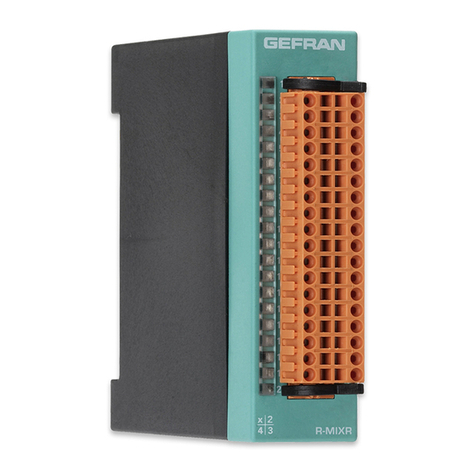
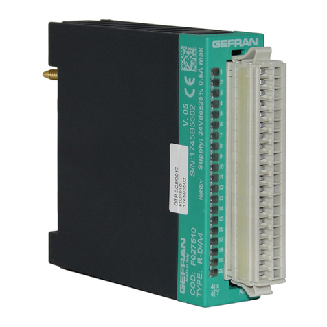
Dimensions: 92x90x25.4mm
Weight: 120g.
Fastening: snaps on R-BUS(x)
Protection level: IP20
Connector: 8 pin female with spring lock
Connector: 36 pin female with spring lock
AMBIENT CONDITIONS
Working temperature: 0...50°C
Storage temperature: -20...70°C
Humidity: max. 90% Ur non-condensing
The connections of the module call for:
External power supplies:
• 24VDC ±25% 200mA max. plus the current needed to load the outputs. Use unipolar cable with max section 1 mm2. Do not attach lug.
Transducer inputs:
• Potentiometer: use 3-pole shielded cable with max section 0.5 mm2. Do not attach lug. Connect shield directly to ground plate and as close as
possible to the module.
• Thermocouple: In case of isolated thermocouples, ground the negative pole of the input as close as possible to the module. Do not attach lug.
• Strain-gauge: use 4 or 6-pole shielded cable with max section 0.5 mm2. Do not attach lug. Connect shield directly to ground plate and as close as
possible to the module. Use external calibration wires to calibrate the transducer.
• Current transformer (CT)
• Use 2-pole cable with max section 0.5 mm2. Do not attach lug
• Amplified inputs, use 2 or 3-pole shielded cable with max section 0.5 mm2. Do not attach lug.
Connect shield directly to ground plate and as close as possible to the module.
• Linear analog input:
use 2-pole shielded cable with max section 0.5 mm2. Do not attach lug. Connect shield directly to ground plate and as close as possible to the
module.
• 2-pole analog outputs ±10V or ± 0/20mA:
use shielded cable with max section 0.5 mm2. Do not attach lug. Connect shield directly to ground plate and as close as possible to the module
• Digital inputs / outputs:
use cable max 0.1mm2. Do not attach lug.
NOTE:
The shield of the analog inputs / outputs must be connected near the module and directly to the ground plate.
