Triac output (option) 20...240Vac ±10%, 3A max.
Snubberless, inductive and resistive load
I2t = 128A2S
-1999...9999 (settable decimal point)
Can be converted into engineering units by
inserting a multiplier or divisor (for example, for
display / intercept of rpm)
Scale limits
Faceplate protection IP65
Working / Storage temperatures 0 to 50°C / -20 to 70°C
Relative humidity 20 to 85%, non-condensing
Installation Panel mounting, extractable from front
Weight 320g for the complete version
Sensor or transducer power supply 5Vdc, 12 Vdc, 120mA max
24 Vdc ± 10%, 50mA max filtered only
Alarms (set points) Maximum of three configurable alarms:
absolute, deviation, symmetrical deviation.
Adjustable hysteresis
Alarm masking
- exclude on power-up
- latch reset from key and/or external contact
- insert delay filter (DON, DBI, DOF, DFO)
- set minimum intervention time
Relay contact NO (NC) 5A, 250V a cosϕ=1
Logic output type D 11Vdc, Rout = 220Ω(6V/20mA)
Logic input Ri = 5,6KΩ(24V, 4mA), 1500V isolation
Logic input functions configurable for alarm memory reset, hold, flash,
zero, selection of max., min. peak value, peak-
peak
Analog retransmission (option) 4 to 20mA, max. 150 Ωload
Fuse (inside device, not
operator serviceable) 100 to 240Vac/dc - type T - 500mA - 250V
11 to 27Vac/dc - type T - 1.25A - 250V
Power supply (switching) (standard) 100...240Vac/dc ±10% max 11,5VA
(optional) 11...27Vac/dc ±10% max 9VA
50/60Hz
Display 4 digit red LED’s, digit height 14mm
Keys 3 mechanical keys (Raise, Lower, F)
Accuracy 0.1% in autorange mode ± 1 digit with fixed f.s.
Main input
- mechanical contact, no voltage, configurable in
opening/closing, 100Hz filter insertable from
configuration
- from logic control under voltage with amplitude
0.5...30 Vdc, 6 mA max, for proximity PNP or
NPN (inductive or capacitive), encoder or
NAMUR 2 or 3 wires
- maximum frequency of input signal with duty
cycle 50% settable 1, 2, 3, 4, 10, 20, 40, 100 KHz
- from alternate control 30...500V peak, 1 mA max.
maximum frequency 10KHz
minimum frequency 0.5Hz in sinusoidal mode
For correct and safe
installation, follow the
instructions and observe
the warnings contained
in this manual.
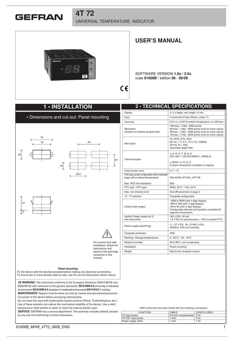
1 • INSTALLATION
•Dimensions and cut-out: Panel mounting
Panel mounting:
Fix the device with the bracket provided before making any electrical connections.
To mount two or more devices side by side, use the cut-out dimensions shown above.
CE MARKING: EMC (electromagnetic compatibility) conformity to EEC Directive
89/336/CEE with reference to the generic Standard EN50082-2 (immunity in industrial
environments) and EN50081-1 (emission in residential environments). BT (low voltage)
conformity to Directive 73/23/CEE as modified by Directive 93/68.
MAINTENANCE: Repairs must be done out only by trained and specialized personnel.
Cut power to the device before accessing internal parts.
Do not clean the case with hydrocarbon-based solvents (Petrol, Trichlorethylene, etc.).
Use of these solvents can reduce the mechanical reliability of the device. Use a cloth
dampened in ethyl alcohol or water to clean the external plastic case.
SERVICE: GEFRAN has a service department. The warranty excludes defects caused
by any use not conforming to these instructions.
2 •TECHNICAL SPECIFICATIONS
FUNCTION CABLE LENGTH USED
Input 1 mm23 m
Power supply cable 1 mm21 m
Relay output cables 1 mm23,5 m
EMC conformity has been tested with the following connections
!
40F 96
CONFIGURABLE FREQUENCY INDICATOR - INTERCEPTOR
SOFTWARE VERSION 1.0x
code 81671B / edition 06 - 03/08
USER’S MANUAL
Environmental conditions of use for internal use only, altitude up to 2000m
1
81671B_MHW_40F96_0308_ENG
