gefran 650 L Quick guide

INSTALLATION AND
INSTRUCTION MANUAL
code: 80224A
80224_MHW_650 L - 1250 L_07-2018_ENG
650 L - 1250 L
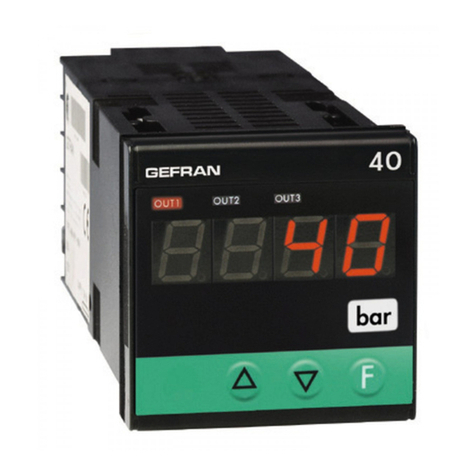
Alarm limit indicator


80224_MHW_650 L - 1250 L_07-2018_ENG - 1
CONTENTS..........................................................................1
Introduction.........................................................................3
Device data ......................................................................................3
Warnings and safety.........................................................................3
Symbols used in this manual ...........................................................4
Glossary ...........................................................................................4
Disclaimer.........................................................................................5
Copyright..........................................................................................5
1. General description.................................................. 6
1.1. Profile .....................................................................................6
1.2. Differences between models..................................................7
1.3. Indicator 650 L .......................................................................8
1.3.1. Display and keys 650 L...........................................................8
1.3.2. Cutout and mounting dimensions..........................................9
1.4. Indicator 1250 L ...................................................................10
1.4.1. Display and keys 1250 L.......................................................10
1.4.2. Cutout and mounting Dimensions .......................................11
2. Installation............................................................... 12
2.1. Mounting the indicator .........................................................12
2.1.1. General considerations.........................................................12
2.1.2. Mounting dimensions ...........................................................12
2.1.3. Protection against infiltration of dust .......................................
and water ........................................................................12
2.1.4. Vibrations...............................................................................13
2.1.5. Minimum space for ventilation .............................................13
2.1.6. Positioning.............................................................................13
2.1.7. Fastening to the panel ..........................................................13
2.2. Connections .........................................................................14
2.2.1. General considerations.........................................................14
2.2.2. Electromagnetic compatibility (EMC)...................................14
2.2.3. Cables ...................................................................................14
2.2.4. Power supply ........................................................................14
2.2.5. Connecting inputs and outputs............................................15
2.3. 650 L connection diagrams..................................................16
2.3.1. General diagram....................................................................16
2.3.2. Power supply ........................................................................17
2.3.3. Inputs.....................................................................................17
2.3.4. Outputs..................................................................................17
2.3.5. Options..................................................................................18
2.4. 1250 L connection diagrams................................................19
2.4.1. General diagram....................................................................19
2.4.2. Power supply ........................................................................20
2.4.3. Inputs.....................................................................................20
2.4.4. Outputs..................................................................................20
2.4.5. Digital inputs..........................................................................21
2.4.6. Serial line ...............................................................................21
2.4.7. Analog output........................................................................21
2.5. RS485 serial connection diagram ........................................22
3. Commissioning.......................................................23
3.1. Information on displays and use of keys..............................23
3.1.1. Menu navigation....................................................................23
3.1.2. Displays.................................................................................23
3.1.2.1. Display characters ...................................................23
3.2. Power-on sequence .............................................................24
3.1.2.2. Scrolling messages..................................................24
3.3. First power-on ......................................................................25
3.3.1. Fast configuration .................................................................25
3.4. Setting up quick configuration .............................................29
3.4.1. Setting up the Alarm ............................................................29
CONTENTS
CONTENTS
4. Configuration ..........................................................30
4.1. Programming/Configuration Menu.......................................30
4.1.1. First: know what you’re doing ..............................................30
4.1.2. Passwords.............................................................................30
4.1.3. Password in the User Menu .................................................30
4.2. Main menu ...........................................................................31
4.3. Legend for submenus and parameters................................32
4.3.1. Submenu...............................................................................32
4.3.2. Parameters............................................................................32
4.4. INFO Submenu - information display...................................33
4.4.1. SW.VER - Software Version..................................................34
4.4.2. CODE - Serial address of the indicator................................34
4.4.3. ERROR - Primary input error................................................34
4.4.4. SAP.C - SAP code.................................................................34
4.4.5. SEr.n - Serial address of the indicator..................................34
4.4.6. xxxxx - Model of indicator....................................................35
4.4.7. INDIC - Type of indicator ......................................................35
4.4.8. OUT.A1 - Analog output 1 available .....................................35
4.4.9. x.IN.DG - Digital input available............................................35
4.4.10. RS485 - RS485 serial port available ....................................35
4.4.11. Out1 - Type of output ...........................................................36
4.4.12. Out2 - Type of output ..........................................................36
4.4.13. Out3 - Type of output ..........................................................36
4.4.14. OUT1.S - Number of cycles output 1 .................................36
4.4.15. OUT2.S - Number of cycles output 2 .................................36
4.4.16. OUT3.S - Number of cycles output 3 .................................37
4.4.17. T.DAYS - Total working days ................................................37
4.4.18. P.DAYS - Partial working days..............................................37
4.4.19. T.INT - Internal temperature of indicator ..............................37
4.4.20. T.MIN - Minimum internal temperature of the indicator.......37
4.4.21. T.MAX - Maximum internal temperature of the indicator ....38
4.5. I.MAIN Submenu - Configuration of main input...................39
4.5.1. tyPE - Selecting sensor type ................................................40
4.5.2. SBR.E - Enabling Sensor Break Alarm (SBR) ......................41
4.5.3. Lin - Linearization type..........................................................42
4.5.4. Unit - Displayed engineering units .......................................42
4.5.5. FILT - Digital filter ..................................................................42
4.5.6. FILT.D - Digital filter on PV display........................................43
4.5.7. DEC.P - Number of decimals displayed ..............................43
4.5.8. LO.SCL - Lower limit of scale...............................................43
4.5.9. HI.SCL - Upper limit of scale................................................44
4.5.10. OF.SCL - Scale offset correction..........................................44
4.5.11. LO.AL - Lower limit for alarms..............................................44
4.5.12. HI.AL - Upper limit for alarms...............................................44
4.6. ALARM Submenu - Configuration of alarms........................45
4.6.1. ALARM - Selecting the alarm to be configured...................46
4.6.2. d.i.x - Selecting direct or inverse alarm................................46
4.6.3. A.r.x - Selecting absolute or deviation alarm .......................46
4.6.4. n.S.x - Selecting hysteresis type..........................................46
4.6.5. PWON.E - Disabling the alarm at power-on ........................47
4.6.6. LATCH - Set alarm latching ..................................................47
4.6.7. HYSTE - Hysteresis ..............................................................47
4.6.8. DELAY - Alarm trip delay ......................................................48
4.6.9. MSG.AL - Alarm message....................................................48
4.6.10. MSG.AN - Alarm reset message..........................................48
4.6.11. BLK.AL - Flashing of PV display...........................................49
4.6.12. BLK.AN - PV display alarm flashing with alarm reset..........49
4.7. I.DIGT Submenu – Configuring digital inputs.......................50
4.7.1. I.DIG.N - Selecting the digital input......................................51
4.7.2. S.in.x - Defining the input state ............................................51
4.7.3. F.in.x - Selecting the assigned function................................51
4.7.4. MSG.IN - Selecting the digital input message.....................51
4.8. OUTPU Submenu – Configuring outputs............................52
4.8.1. OUT.N - Selecting the output ...............................................53
4.8.2. S.ou.x - Defining the output state ........................................53
4.8.3. F.ou.x - Selecting the function assigned to relay, logic or
Triac output ...........................................................................53
80224_MHW_650 L - 1250 L_07-2018_ENG - 2
4.8.4. IN.DG.N - Setting the digital input number..........................53
4.8.5. SWTCH - Output cycle limit alarm .......................................54
4.8.6. FAULT - State of output with broken input ..........................54
4.8.7. MSG.OU - Selecting the output message ...........................54
4.9. OUT.AN - Submenu – Configuring the analog retransmission
output...................................................................................55
4.9.1. S.o.A1 - Defining the signal direction of the analog output.56
4.9.2. t.o.A1 - Defining the type of analog output..........................56
4.9.3. LO.A1 - Scale minimum........................................................56
4.9.4. HI.A1 - Scale maximum........................................................56
4.10. MODE Submenu – Functionality configuration....................57
4.10.1. dIG - Defining type of digital inputs......................................58
4.10.2. ALRM.N - Number of alarms enabled..................................58
4.10.3. TY.TM - Base time settings for ALARM1 alarm condition
persistence............................................................................58
4.11. SERIA Submenu – Configuring serial communication.........59
4.11.1. CODE - Identification code...................................................60
4.11.2. KBAUD - Selecting communication speed..........................60
4.11.3. PAr - Selecting parity ............................................................60
4.12. HMI Submenu – Configuring the display and keypad .........61
4.12.1. bArG - Selecting the bargraph display.................................62
4.12.2. MSG.LO - -Lo message display...........................................62
4.12.3. MSG.HI - -Hi message display............................................62
4.12.4. MSG.ER - Err message display............................................63
4.12.5. MSG.SB - Sbr message display ..........................................63
4.12.6. LAnG - Display language.....................................................63
4.12.7. SPEED - Message scrolling speed ......................................63
4.12.8. BACKL - Backlighting level...................................................64
4.12.9. QUICK - Quick configuration menu .....................................64
4.13. LINRZ Submenu – Configuring custom linearization ...........65
4.13.1. STP.xx - Value of step xx ......................................................66
4.13.2. MV.STA - Setting mV at start of scale ..................................66
4.13.3. MV.FUL - Setting mV at full scale.........................................66
4.13.4. MV.50C - Setting mV at temperature of 50 °C.....................66
4.14. US.CAL Submenu – User calibrations .................................67
4.14.1. U.CAL - Selecting the user calibration.................................68
4.14.2. FI.CAL - Resetting the factory calibration............................68
4.14.3. C.LOW - Calibrating minimum current / voltage .................68
4.14.4. C.HIGH - Calibrating maximum current / voltage................68
4.14.5. RTD.LO - Calibrating minimum resistance value.................69
4.14.6. RTD.HI - Calibrating maximum resistance value .................69
4.14.7. C.LO - Setting analog output minimum...............................69
4.14.8. C.HIG - Setting analog output maximum ............................69
4.15. PASC0 – Setting level 0 password.......................................70
4.16. PASC1 - Setting level 1 password .......................................70
4.17. PASC2 - Setting level 2 password .......................................70
4.18. FI.CFG - Entering the reset code ........................................70
5. Examples and application notes...........................71
5.1. Control application...............................................................71
5.1.1. Connection diagram .............................................................71
5.1.2. Quick configuration procedure for model 650L - R-RR0-
00000-1-G.............................................................................72
5.2. 4-point input correction........................................................73
5.3. Alarms ..................................................................................74
5.3.1. Generic alarms AL2-4..........................................................74
6. Programming with PC............................................ 75
6.1. Indicator-PC connection ......................................................75
6.2. Programming Tool ................................................................75
6.2.1. GF_eXpress...........................................................................75
6.2.1.1. System requirements............................................... 75
7. Operator guide........................................................ 76
7.1. Displays and keys ................................................................76
7.1.1. Navigating the menus...........................................................76
7.2. Power-on..............................................................................76
7.3. Operation as indicator..........................................................76
7.4. Errors during operation ........................................................77
7.5. Configuration (User menu) ...................................................78
8. Maintenance ...........................................................81
8.1. Replacing the indicator ........................................................81
8.2. Replacing the gasket............................................................81
8.3. Cleaning ...............................................................................81
8.4. Disposal ...............................................................................81
9. Technical data......................................................... 82
10. Order methods........................................................ 85
10.1. 650 L model list....................................................................85
10.2. 1250 L model list..................................................................85
11. Accessories ............................................................86
CONTENTS

80224_MHW_650 L - 1250 L_07-2018_ENG - 3
INTRODUCTION
INTRODUCTION
Device data
Warnings and safety
This information will be needed by Gefran Customer Service in order to provide technical assistance. In the space below,
write the order code and other plate data shown on the label attached to the outside of instrument (see figure).
Make sure that you always have the latest version of this
manual, downloadable at no cost from Gefran’s website
(www.gefran.com).
The devices described in this manual must be installed by
trained personnel in conformity to current laws and regula-
tions, following all of the instructions in this manual.
Installers and/or maintenance personnel MUST read this ma-
nual and follow all of the instructions contained herein and
in the attachments. Gefran will not be liable for any damage/
harm caused to persons and/or property, or to the device
itself, if any instructions are not followed.
This manual must always be available to people who use or
work on the devices described herein.
Before using the instruments 650 L - 1250 L, the operator
must be trained with regard to operating, emergency, dia-
gnostics, and maintenance procedures.
If the instruments 650 L - 1250 L are used in applications
with risk of harm to persons or damage to machines or ma-
terials, auxiliary alarm devices must be installed.
It is advisable, during normal operations, to provide a way to
check if the alarms have tripped.
DO NOT touch the terminals when the device is powered.
In case of malfunction, before contacting Gefran Custo-
mer Service, we recommend you to consult “Troublesho-
oting” in the Maintenance section and the F.A.Q. (Fre-
quently Asked Questions) section on Gefran’s website
(www.gefran.com).
Serial
number SN
Finished
product code CODE
Order
code TYPE
Supply
voltage SUPPLY
Firmware
version VERS.

80224_MHW_650 L - 1250 L_07-2018_ENG - 4
INTRODUCTION
Symbols used in this manual
Glossary
Pay attention when you see these symbols in the manual.
Indicates very important information on correct
product function or on safety, or an instruction that
MUST be followed.
Indicates risk for the safety of the installer or user
due to the presence of high voltage.
Indicates a point to which the reader’s attention is
called.
Indicates a suggestion that could be useful for
better use of the device
Indicates a reference to other technical documents
that can be downloaded from www.gefran.com.
WWW
4...20 mA Current used as signal transmitted by
certain sensors or in a specific way to
control a device, such as a motorized
valve.
Alarm Output that trips when a certain condi-
tion is reached, for example, a defined
temperature
Hysteresis The phenomenon in which the value of
a physical property lags behind changes
in the effect causing it, as for instance
when thermocouples temperature lags
behind the heater temperature
Pt100 A commonly used temperature measu-
rement device. At 0°C its resistance is
100 ohm, normal extension cables can
be used.
PV Acronym for Process Value, i.e., the value
that the process variable (temperature,
valve opening, etc.) has at that moment.
Sensor Device that translates physical phe-
nomena (such as change in resistance
based on temperature) into electrical si-
gnals that can be acquired and proces-
sed by the indicator
Thermocouple Sensor that transmits an electrical signal
of a few millivolts. It needs specially de-
signed extension cables

80224_MHW_650 L - 1250 L_07-2018_ENG - 5
Disclaimer
Copyright
Although all of the information in this manual has been ca-
refully checked, Gefran S.p.A. assumes no liability regarding
the presence of any errors or regarding damage to property
and/or harm to individuals due to any improper use of this
manual
Gefran S.p.A. also reserves the right to change the contents
and form of this manual, as well as the characteristics of the
devices described herein, at any time and without notice.
The technical data and performance levels specified in this
manual are to be considered a guide for the user in order to
determine the device’s suitability for a defined use, and do
not constitute a guarantee.
They may be the result of test conditions at Gefran S.p.A.,
and the user must compare them to his/her real application
requirements.
Under no circumstances will Gefran S.p.A. be liable for any
damage to property and/or harm to individuals due to tam-
pering, incorrect or improper use, or use not conforming to
the characteristics of the indicator and to the instructions
contained in this manual.
This manual and its attachments may be freely reproduced
provided its contents are not changed in any way and provi-
ded every copy includes the above Disclaimer and the state-
ment of ownership of Gefran S.p.A.
Gefran and GF_eXpress are registered trademarks of Gefran
S.p.A.
This manual may make reference to or reproduce remove
hyphen and logos of third parties. Gefran S.p.A. acknowled-
ges such parties’ ownership of these trademarks and logos.
INTRODUCTION

80224_MHW_650 L - 1250 L_07-2018_ENG - 6
1. GENERAL DESCRIPTION
1.1. Profile
Indicators 650 L and 1250 L are a family of devices used to
limit overheating in industrial processes.
In the event of alarm, the instrument latches the fault con-
ditions until reset by the operator. Reset can be run by the
operator from the front key (red R), from the digital input
(optional) or serial line (optional).
As an additional feature, the instrument counts the number
of times the alarm limit is exceeded and total amount of
time the alarm is active.
This information can help to evaluate furnace deterioration
and plan maintenance work.
The devices have the same main characteristics and the
same range of functions. They differ in size (1/16, 1/8 DIN),
the amount of information shown on the display, and the ma-
ximum number of digital inputs.
The displays show the process values, plus multilingual
scrolling messages for diagnostics and alarms.
The 1250 L model includes a segmented bar that graphical-
ly displays the temperature deviation from the alarm limit.
Configuration and unit operation is done with the front keys.
The keys have
dual-function LEDs indicating pressing of the keys. The
LEDs provide feedback for pressed
key and also provide guidance for permitted operations.
Initial commissioning is simplified by guided configuration
text prompts that cover the commonly used
base parameters accompanied by in line help messages.
With GF_eXpress software and PC, you can program the ex-
tended configuration, create recipes and update the firmwa-
re without having to apply power to the instrument.
Thanks to the Smart Configurator function, you obtain the
required configuration by answering a few simple questions.
The initial parameters can always be reset, both from the
keypad and from the GF_eXpress software.
The devices offer complete diagnostics (broken or incorrect
connection of sensor), operation count, settable alarm limits
(useful for scheduling preventive maintenance)
A trigger meter and alarm memory reset timer are available
for alarm 1.
Maintenance of the system in which the device is installed
is made easier by the ability to replace the instrument at any
time simply by removing it from the faceplate.
No additional steps are needed.
650 L 1250 L
1. GENERAL DESCRIPTION

80224_MHW_650 L - 1250 L_07-2018_ENG - 7
1. GENERAL DESCRIPTION
1.2. Differences between models
650 L 1250 L
Display dimensions 35 × 30 mm (1.38” x 1.18”) 37 × 68 mm (1.46” x 2.68”)
PV display 4 digit, 7 seg., H = 17 mm (0.67”) 4 digit, 7 seg., H = 17 mm (0.67”)
SV display 5 digit, 14 seg., H = 7 mm (0.27”) 4 digit, 7 seg., H = 14 mm (0.55”)
Display F n/a 5 digit, 14 seg., H = 9 mm (0.35”)
Bargraph n/a 11 segments
Keys 4 4
Max. digital inputs 3 5
Power dissipation 5 W 10 W
Dimensions 48 × 48 mm (1.89” x 1,89”) 1/16 DIN 48 x 96 mm (1.89” x 3.78”) 1/8 DIN
Weight 0,16 kg (0.35 lb) 0,24 kg (0.53 lb)
n/a = not available

80224_MHW_650 L - 1250 L_07-2018_ENG - 8
1.3. Indicator 650 L
Main features
• Operator interface with large LCD Display, customi-
zable, with choice of colors
• Scrolling diagnostic messages, configurable, in the
selected language
• Easy, guided configuration, copy/paste parameters
even with power off
• Different password levels
• Universal input configurable for thermocouples, RTDs,
Current/voltage inputs
• Relay, logic,
• RS485 serial communication in Modbus RTU
• Removable faceplate for quick replacement
• Sampling time 60 ms
1.3.1. Display and keys 650 L
Figure 1 - Description of 650 L display and keys
1. Temperature unit of measurement
2. ALARM status
3. Alarm reset key
4. Up/down keys: raise/lower the value of the parameter
displayed on the SV or PV display.
5. F key: lets you navigate among menus and parameters.
Confirms the parameter value and selects the next pa-
rameter.
6. Key pressed signals.
7. SV display: Alarm 1 limit, description of para-
meters, diagnostic and alarm messages.
It can be used to view the alarm limit and displays the
associated message in the event of alarm.
8. PV display: process variable, parameter values.
Dimensions 48 x 48 x 80 (1.89” x 1,89”) 1/16 DIN
1
6
7
8
2
3 54
1. GENERAL DESCRIPTION

80224_MHW_650 L - 1250 L_07-2018_ENG - 9
1.3.2. Cutout and mounting dimensions
48 mm
1.89 in
48 mm
1.89 in
80 mm
3.15 in
45 mm
10 mm
0.39 in
58 mm
2.28 in
70 mm
2.76 in
70 mm
2.76 in
45 mm
1.78 in
1.78 in
+0.6
- 0.0
+0.6
- 0.0
Figure 2 - 650 L Cutout and mounting Dimensions
1. GENERAL DESCRIPTION

80224_MHW_650 L - 1250 L_07-2018_ENG - 10
1.4. Indicator 1250 L
Main features
• Operator interface with large LCD Display, customi-
zable, with choice of colors
• Scrolling diagnostic messages, configurable, in the se-
lected language
• Easy, guided configuration, copy/paste parameters
even with power off
• Different password levels
• Universal input configurable for thermocouples, RTDs,
Current/Voltage inputs
• Relay, logic,
• RS485 serial communication in Modbus RTU
• Removable faceplate for quick replacement
• Sampling time 60 ms
1.4.1. Display and keys 1250 L
Figure 3 - Description of 1250 L display and keys
1. Temperature unit of measurement
2. ALARM status
3. Alarm reset key
4. Up/down keys: raise/lower the value of the parameter
displayed on the SV or PV display.
5. F key: lets you navigate among menus and parameters.
Confirms the parameter value and selects the next pa-
rameter.
6. Alarm 1 limit deviation display
7. Key pressed signals.
8. Display F: parameters, diagnostic and alarm messages.
9. SV display: Alarm 1 limit, parameters being set.
10. PV display: process variable, parameter values.
Dimensions 48 × 96 × 80 mm (1.89” x 3.78”) 1/8 DIN
1
2
3 54
6
7
8
9
10
1. GENERAL DESCRIPTION

80224_MHW_650 L - 1250 L_07-2018_ENG - 11
1.4.2. Cutout and mounting Dimensions
48 mm
1.89 in
108.6 mm
4.28 in
96 mm
3.78 in
80 mm
3.15 in
92 mm
3.64 in
115 mm
4.53 in
0.39
in
10 mm
70 mm
2.76 in
45 mm
1.78 in
+ 0.6
- 0.0
+ 0.8
- 0.0
Figure 4 - 1250 L Cutout and mounting Dimensions
1. GENERAL DESCRIPTION

80224_MHW_650 L - 1250 L_07-2018_ENG - 12
2. INSTALLATION
Attention! The devices described in this manual must be installed by trained personnel in conformity to current laws
and regulations, following all of the instructions in this manual.
Before installing, check that the indicator is in whole condition and was not damaged in shipment. Make sure that
the package contains all of the accessories listed on the accompanying document, especially the gasket and the
fastening brackets.
Check that the order code matches the configuration required for the intended application (supply voltage, number
and type of inputs and outputs). See Chapter 10 - Ordering code - to check the configuration corresponding to
each order code.
Attention! If even one of the requirements mentioned above is not satisfied or there is noticeable damage to the unit,
discontinue the installation and contact your Gefran dealer or Gefran Customer Service.
2.1. Mounting the indicator
2.1.1. General considerations
The instrument is designed for permanent indoor installation.
It must be mounted in electrical panels or in panels control-
ling machines or production process plants that are able to
protect the exposed terminals on the rear of the instrument.
Attention! DO NOT install the instrument in a po-
tentially inflammable or explosive atmosphere.
Attention! the instrument is used in applications
with risk of harm/damage to persons/property, it
MUST be connected to dedicated alarm devices.
It is advisable to provide a means of alarm checking
and intervention even during instrument normal
operation or through the equipment where the in-
strument is monitored.
The indicator must be installed in a location that is not subject
to sudden temperature changes or to freezing or condensa-
tion, and no corrosive gases must be present.
The indicator can work in Pollution Degree 2 environments.
Do not allow scrap or metal particles from machining or con-
densation products to reach the device.
The instrument is sensitive to strong electromagnetic fields.
Do not position it near radio devices or other equipment that
may generate electromagnetic fields, such as power contac-
tors, relays, thyristor power units (especially phase angle),
motors, solenoids, transformers, high-frequency welders,
etc.
2.1.2. Mounting dimensions
For correct installation, respect the dimensions of each hole
and the distance between adjacent holes shown in the figu-
res for each model (“Figure 2 - 650 L Cutout and mounting
Dimensions” on page 9, “Figure 4 - 1250 L Cutout and
mounting Dimensions” on page 11.
Attention! The support on which the operator panel
is mounted must:
• be sufficiently rigid and robust to support the
device without bending during use;
• be from 1 to 4 mm thick to allow the device to
be fastened with the supplied bracket.
2.1.3. Protection against infiltration of dust
and water
The front of the instrument has an IP65 protection index, so
the device can be installed without problems in rooms that
are very dusty or subject to splashing water provided:
• the housing in which the device is inserted is dust-tight
and watertight;
• the support on which the device is installed is perfectly
smooth and without undulations on the front;
• the hole on the support respects the specified dimen-
sions;
• the device is fully tightened to the support to ensure that
the gasket inserted between the device and the panel is
watertight
Attention! If not adequately protected, the instru-
ment has an IP20 protection index (rear container
and terminal board.
2. INSTALLATION

80224_MHW_650 L - 1250 L_07-2018_ENG - 13
2. INSTALLATION
2.1.4. Vibrations
The instrument can support vibrations from 10 to 55 Hz,
20 m/s2, in all directions (X, Y and Z).
If the device is mounted on a support that exceeds these
limits, it is recommended to provide a suspension system to
reduce vibrations.
2.1.5. Minimum space for ventilation
The temperature in the housing containing the instrument
must NEVER exceed 55°C. NEVER block the ventilation slits.
Advice. The lower the temperature in which the de-
vice works, the longer the life of its electronic com-
ponents.
Attention! Forced cooling (for example, with a fan)
of the rear of the instrument may cause measure-
ment errors.
2.1.6. Positioning
The indicator must be positioned so that the display is not
subject to direct sunlight or to very strong sources of light.
If necessary, filter direct light, for example, with a reflecti-
ve screen. The instrument must be tilted between 30° and
120°, as shown in the figure.
Figure 5 - Positioning the indicator
2.1.7. Fastening to the panel
1. Insert the die-cut rubber gasket between the instrument
and the panel. The gasket (supplied) is required for en-
suring the declared protection index of the faceplate.
2. Insert the device into the hole previously made on the
panel.
3. Place the supplied bracket(s) onto the rear of the instru-
ment.
4. Tighten the screws to fasten the device to the panel.
The tightening torque must be between 0,3 and 0,4 N m.
120 °
30 °
Controllers not in scale
The following figures show how to fasten the two indicator
models.
Figure 6 - Fastening the 650 L
Figure 7 - Fastening the 1250 L

80224_MHW_650 L - 1250 L_07-2018_ENG - 14
2.2. Connections
Attention! Failure to follow the instructions in this
section may cause problems in electrical safety and
electromagnetic compatibility, in addition to voiding
the warranty.
2.2.1. General considerations
1. Connected external circuits must be isolated for both
single and differential inputs.
2. When using shielded cables, the shield must be groun-
ded at a single end point, preferably at the instrument
end.
3. Input cables must be physically separated from power
cables, output cables, and power connections.
4. Do not connect unused terminals.
5. Do not overtighten connection terminals. The recom-
mended torque is 0.5 Nm.
6. When making connections,manitain proper polarity
where required.
7. Do not bend or twist the cables
8. After connecting the cables, install the transparent co-
ver to protect the terminals. The terminal teeth ensure
the correct orientation of the cover.
2.2.2. Electromagnetic compatibility (EMC)
For electromagnetic conformity, the strictest general rules
have been applied, using the following test configuration:
Connection Cable
section Length
Power supply 1 mm2(17 AWG) 1 m (39.37”)
Relay 1 mm2(17 AWG) 3,5 m (137.79”)
Serial port 0,35 mm2(21 AWG) 3,5 m (137.79”)
Thermocouple 0,8 mm2(18 AWG) 5 m (196.85”)
compensated
Potentiometer,
linear, “PT100”
resistance
thermometer
1 mm2(17 AWG) 3 m (118.11”)
Digital input/
outputs 1 mm2(17 AWG) 3,5 m (137.79”)
2.2.3. Cables
Always use cables appropriate for the voltage and current
limits specified in the Technical Characteristics.
Use copper cables with 60/75°C insulation.
Use twisted and shielded cables for non-power connections.
The instrument’s terminal board has screw terminals (M3)
that accept stripped cables and crimped terminals for a ti-
ghtening torque of 0.5 N m.
Two ring or crimped fork terminals can be connected on
each terminal
The following table shows the characteristics of the cables
and terminals that can be used.
Cable / terminal Cable / terminal
section Terminal size
Rigid cable 0,2...2,5 mm2
(24...14 AWG)
Twisted 0,2...2,5 mm2
(24...14 AWG)
Tag terminal
(to be crimped)
0,25...2,5 mm2
(23...14 AWG)
5,8
Fork terminal
(to be crimped)
5,8 mm max
(0.23”)
5,8
Ring terminal
(to be crimped
5,8 mm max
(0.23”)
Attention! Tie the cables, in pairs, to prevent ben-
ding at the terminal connections.
2.2.4. Power supply
Attention! Before powering the instrument, make
sure that the supply voltage matches the one
shown on the instrument data plate.
Because the instrument does not have a switch, a discon-
nect and fuse must be inserted ahead of the device. The di-
sconnect, or isolator, must be positioned near of the device
and must be easily reached by the operator.
A single disconnect can control multiple instruments.
The instrument must be powered by a line separated from
the one used for electromechanical power devices (relays,
contactors, solenoids, etc).
It is recommended to install a ferrite core on the power line,
as close as possible to the device, to limit the instrument’s
susceptibility to electromagnetic noise.
If the instrument’s power line is heavily disturbed by noise,
it is advisable to use an isolation transformer only for the
instrument, grounding the shield.
Use appropriate line filters when near high-frequency gene-
rators or arc welders.
Use a voltage stabilizer if there are wide shifts in line voltage.
20...27 VAC/VDC models must be powered by a class II or
low-voltage limited-energy source.
The power supply must use a line separated from the one
used for electromechanical power devices, and low-voltage
power cables must run along a path separated from the sy-
stem or machine power cables.
Attention! Make sure the ground connection is effi-
cient. Absent or inefficient grounding can make the
device unstable due to excessive noise.
Specifically, check that:
• voltage between object and ground is < 1 V;
• resistance is < 6 Ω.
2. INSTALLATION

80224_MHW_650 L - 1250 L_07-2018_ENG - 15
2.2.5. Connecting inputs and outputs
To prevent noise, the instrument’s input and output wiring
must be kept away from the power cables (high voltages or
high currents).
The input and output cables and the power cables must not
be placed parallel to one another.
Use shielded cables or separate cable trays.
To connect the output to an inductive load (relay, contactor,
valve, motor, fan, solenoid, etc.) that works in AC, mount a
snubber, i.e., an RC group (resistor and condenser in series)
placed parallel to the load. Installing this filter lengthens the
life of the relays.
NOTE: All condensers must conform to VDE (class X2) stan-
dards and support voltage ≥ 220 VAC.
The power of the resistor must be ≥ 2 W.
~
Out
R
C
L
Figure 8 - Snubber connection diagram (AC)
For inductive loads that work in DC, mount a 1N4007 diode
parallel to the coil.
Out LD
+ -
Figure 9 - Snubber connection diagram (DC)
The filters must be connected as close as possible to the
instrument.
Attention! If the instrument is connected to devi-
ces that are NOT electrically isolated (such as ther-
mocouples), ground with a separate conductor to
prevent grounding directly through the machine
structure.
2. INSTALLATION

80224_MHW_650 L - 1250 L_07-2018_ENG - 16
2.3. 650 L connection diagrams
2.3.1. General diagram
6
5
4
3
2
1
7
8
9
10
11
12
19
20
21
22
23
24
7
8
9
10
11
12
T
T
NO
C
+
-
A1
+
-
+
-
~
PWR
~
B (Data +)
A (Data -)
~
PWR
~
+
-
TT +
-
+
-
B (Data +)
A (Data -)
A1
+
-
NO
C
NO
C
NO
C
5 V, 10 V
OUT 1
OUT 2
IN 1
COM
OUT 3
LEGEND
Power supply
Linear input in
voltage / current
Relay output
Isolated analog output
dry contact digital input
RS485
serial line
Thermocouple input
Input
PT100
JPT100
2 / 3 wires
OPTIONS
2. INSTALLATION

80224_MHW_650 L - 1250 L_07-2018_ENG - 17
2.3.2. Power supply
Powe supply
6
5
4
22
23
24
~
~
PWR
Standard: 100...240VAC/VDC ± 10%
50/60Hz, max 5 VA
Optional: 20...27VAC/VDC ± 10%
50/60Hz, max 5 VA
2.3.3. Inputs
TC Input
6
5
4
3
2
1
+
-
Available thermocouples:
J, K, R, S,T, C, D, B, E, L, U, G, N,
Pt20Rh-Pt40Rh
ITS90 or custom linearization
Maintain polarity
For extensions, use a compensated
cable suitable for the type of TC used
Linear input (V, I)
6
5
4
3
2
1
+
-
linear input voltage
60 mV (Ri > 70kΩ
1 V (Ri > 15kΩ
Linear input in direct current
0/4...20mA, Ri = 50 Ω.
Linear input (V)
65
4
3
2
1
+
-
Linear input in direct voltage
5 V, 10V (Ri > 30kΩ
Input PT100/JPT100 - 2-wires connection
6
5
4
3
2
1
T
Attention:
with this type of connection the line resi-
stance can introduce measurement error,
we recommend that you use wires of ade-
quate cross-section.
The resistance of the three wires must be
equal, and less than 20 ohm.
Input PT100/JPT100 - 3-wires connection
6
5
4
3
2
1
T
Attention:
with this type of connection the line resi-
stance can introduce measurement error,
we recommend that you use wires of ade-
quate cross-section.
The resistance of the three wires must be
equal, and less than 20 ohm.
2.3.4. Outputs
Type of outputs are specified when the indicator is ordered.
Output Out 1 – 5 A relay
6
5
4
3
2
NO
C5 A Relay
250 VAC
Output Out 2 - 5A relay
19
20
21
22
23
24
NO
C
5 A Relay
250 VAC
Output Out 3 - 5A relay
19
20
21
22
23
24
NO
C
5 A Relay
250 VAC
2. INSTALLATION

80224_MHW_650 L - 1250 L_07-2018_ENG - 18
2.3.5. Options
Types of optional inputs and outputs are specified when is
ordered.
Option
7
8
9
10
11
12
-
COM
IN1
+
A (Data -)
B (Data +)
Out A1
Analog output
0...10 V, Imax 20 mA
0...20 mA, 4...20 mA Rout < 500 Ω
Digital inputs
dry contact
Serial line
RS485 2-wires
Option
7
8
9
10
11
12
-
COM
IN1
+
A (Data -)
B (Data +)
Out A1
Analog output
0...10 V, Imax 20 mA
0...20 mA, 4...20 mA Rout < 500 Ω
Digital inputs
NPN 24V, 4.5mA
Serial line
RS485 2-wires
Option
7
8
9
10
11
12
-
COM
IN1
+
A (Data -)
B (Data +)
GND
Out A1
Analog output
0...10 V, Imax 20 mA
0...20 mA, 4...20 mA Rout < 500 Ω
+12/24V max 3.6mA
PNP digital inputs
Serial line
RS485 2-wires
2. INSTALLATION
This manual suits for next models
1
Table of contents
Other gefran Measuring Instrument manuals

gefran
gefran 40T 72 User manual

gefran
gefran SENSORMATE QE2008-W SET User manual

gefran
gefran 40A 48 User manual

gefran
gefran 2308 User manual

gefran
gefran KH-SIL2 Series User manual

gefran
gefran 4A 48 User manual

gefran
gefran KS Series User manual

gefran
gefran 40B 48 User manual

gefran
gefran QE1008-W SET User manual

gefran
gefran 4T72 User manual
Popular Measuring Instrument manuals by other brands

ATD Tools
ATD Tools ATD-8657 owner's manual

Keysight Technologies
Keysight Technologies PXA N9030A Getting started guide

ATP Instrumentation
ATP Instrumentation IEC61672-1 CLASS2 user manual

SPI
SPI SPI-P170 user manual

Precision Medical
Precision Medical 1MFA3001 user manual

Sonel
Sonel MPI-525 operating manual