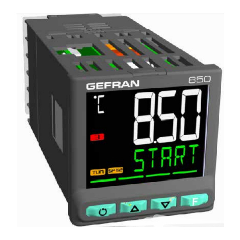
gefran 650 Series User manual

Gefran 650/1250/1350 Temperature Controller – Abbreviated Manual
This booklet contains excerpts from the manufacturer’s Temperature Controller manual. Sections
have been removed that are either not pertinent to the operation or provide detail for advanced
programming. As such, section and page numbers in this manual are not continuous, but rather
duplicate the complete programming manual. The complete Installation and Instruction Manual
for programming the controller can be accessed at www.gefran.com.
Gefran 650/1250/1350 Temperature Controller – Abbreviated Manual
40524-04 Rev0

1
Excerpts from controller manual
3. Commissioning.......................................................33
3.1. Information on displays and use of keys..............................33
3.1.1. Navigating the menus ................................................33
3.1.2. Displays......................................................................33
3.1.2.1. Display characters ............................................................. 33
3.1.2.2. Scrolling messages............................................................ 34
3.2. Sequence at power-on.........................................................34
TABLE OF CONTENTS
3.3. First power-on ......................................................................35
3.3.1. Fast configuration ......................................................35
3.4. Setting up quick configuration .............................................39
3.4.1. Setting up the Alarm .................................................39
3.4.2. Setting up the Heater Break Alarm ............................40
3.4.3. Setting up the PID......................................................41
4. Configuration ..........................................................43
4.1. Programming/Configuration Menu.......................................43
4.1.1. First: know what you’re doing....................................43
4.1.2. Passwords .................................................................43
4.2. Main menu ...........................................................................44
4.3. Legend for submenus and parameters................................45
4.3.1. Submenu....................................................................45
4.3.2. Parameters.................................................................45
4.4. INFO Submenu - information display...................................46
4.4.1. SW.VER - Versione software ......................................47
4.4.2. CODE - Identifying code of controller........................47
4.4.3. ERROR - Main input error..........................................47
4.4.4. SAP.C - SAP code......................................................47
4.4.5. SEr.n - Serial number of controller.............................47
4.4.6. xxxxx - Model of controller ........................................ 48
4.4.7. xxxxx - Type of controller...........................................48
4.4.8. L.FUNC - Option Logic Functions available ..............48
4.4.9. IN.SPR - Remote setpoint input available .................48
4.4.10. OUT.A1 - Analog output 1 available...........................48
4.4.11. CTx - Current transformer input available..................49
4.4.12. x.IN.DG - Digital input available .................................49
4.4.13. RS485 - RS485 serial port available ..........................49
4.4.14. Out1 - Type of output 1..............................................49
4.4.15. Out2 - Type of output 2.............................................49
4.4.16. Out3 - Type of output 3.............................................50
4.4.17. Out4 - Type of output 4.............................................50
4.4.18. OUT1.S - Number of switchings output 1 ...............50
4.4.19. OUT2.S - Number of switchings output 2 ................50
4.4.20. OUT3.S - Number of switchings output 3 ...............50
4.4.21. OUT4.S - Number of switchings output 3 ...............51
4.4.22. T.DAYS - Total working days......................................51
4.4.23. P.DAYS - Partial working days ...................................51
4.4.24. T.INT - Internal temperature of controller...................51
4.4.25. T.MIN - Minimum internal temperature of the controller
51
4.4.26. T.MAX - Maximum internal temperature of the control-
ler ...............................................................................52
4.4.27. tiME - Internal time.....................................................52
4.4.28. dAtE - Internal date....................................................52
4.5. PR.OPT Submenu - Configuring programs..........................53
4.5.1. PR.OPT - Selecting program .....................................54
4.5.2. FI.STP - Number of first step assigned to program...54
4.5.3. LA.STP - Number of last step assigned to program..54
4.5.4. Strt - Restart mode ....................................................54
4.5.5. RST.SP - Type of control after program restart..........54
4.5.6. WAIT.S - Option to start execution of program..........55
4.5.7. End - Action at end of program .................................55
4.5.8. LIMIT - Limitation of step duration.............................55
4.6. PR.STP Submenu - Configuration of program steps...........55
4.6.1. PR.STP - Programming step......................................57
4.6.2. SETP - Programming step setpoint ..........................57
4.6.3. RAMP.T - Step time ramp ..........................................57
4.6.4. HOLD.T - Hold time in step........................................57
4.6.5. HBB - Enable Hold Back Band function....................57
4.6.6. BAND - Maximum deviation for HBB.........................58
4.6.7. HBB.R - Enabling HBB during ramp..........................58
4.6.8. HBB.H - Enabling HBB during hold...........................58
4.6.9. HBB2 - Enabling HBB with respect to I.SPR............. 58
4.6.10. S.SP.EN - Enabling retransmission of setpoint ..........58
4.6.11. SUB.SP - Setpoint value of slaved controller ............59
4.6.12. S.RM.EN - Enabling ramp for slaved controller .........59
4.6.13. ENBL.1 - Consent 1 to execute step .........................59
4.6.14. ENBL.2 - Consent 2 to execute step .........................59
4.6.15. ENBL.3 - Consent 3 to execute step .........................60
4.6.16. ENBL.4 - Consent 4 to execute step .........................60
4.6.17. EVN.R.1 - Event 1 during step ramp..........................60
4.6.18. EVN.R.2 - Event 2 during step ramp..........................60
4.6.19. EVN.R.3 - Event 3 during step ramp..........................60
4.6.20. EVN.R.4 - Event 3 during step ramp..........................61
4.6.21. EVN.H.1 - Event 1 during step hold ...........................61
4.6.22. EVN.H.2 - Event 2 during step hold ...........................61
4.6.23. EVN.H.3 - Event 3 during step hold ...........................61
4.6.24. EVN.H.4 - Event 4 during step hold ...........................61
4.6.25. GROP.R - Group of parameters assigned to ramp ....62
4.6.26. GROP.H - Group of parameters assigned to hold .....62
4.6.27. MSG.R - Message associated with the ramp ............62
4.6.28. MSG.H - Message associated with the maintenance62
4.7. I.MAIN Submenu - Configuration of main input...................63
4.7.1. tyPE - Selecting sensor type......................................64
4.7.2. Lin - Selecting linearization type................................65
4.7.3. Unit - Selecting the displayed unit of measurement..66
4.7.4. FILT - Digital filter .......................................................66
4.7.5. FILT.D - Digital filter on PV display.............................66
4.7.6. DEC.P - Number of decimals displayed ....................66
4.7.7. LO.SCL - Lower limit of scale ....................................67
4.7.8. HI.SCL - Upper limit of scale .....................................67
4.7.9. OF.SCL - Scale offset correction ...............................68
4.7.10. LO.SP - Lower limit for setpoint.................................68
4.7.11. HI.SP - Upper limit for setpoint..................................68
4.7.12. LO.AL - Lower limit for alarms ...................................68
4.7.13. HI.AL - Upper limit for alarms ....................................68
4.8. I.SPR Submenu - Configuration of remote setpoint input ...69
4.11. ALARM Submenu - Configuration of alarms........................76
4.11.1. ALARM - Selecting the alarm to be configured .........77
4.11.2. rEF.x - Selecting the alarm reference .........................77
4.11.3. d.i.x - Selecting direct or inverse alarm .....................77
4.11.4. A.r.x - Selecting absolute or deviation alarm .............77
4.11.5. n.S.x - Method for applying hysteresis ......................78
4.11.6. PWON.E - Disabling the alarm at power-on ..............78
4.11.7. LATCH - Memorizing the alarm..................................78
4.11.8. HYSTE - Hysteresis....................................................79
4.11.9. DELAY - Alarm trip delay ...........................................79
4.11.10. MSG.AL - Message associated with tripping of alarm ..
79
4.11.11. BLK.AL - Flashing of PV display ................................79
4.13. PID Submenu – Configuring control parameters .................84
4.13.1. S.TUNE - Enabling Self-Tuning ..................................85
4.13.2. SOFT.S - Enabling Soft-Start .....................................85
4.13.3. SOFT.T - Soft-Start Time ...........................................85
4.13.4. A.TUNE - Enabling Auto-Tuning.................................85
4.13.5. Aut.t - Selecting type of Auto-Tuning.........................86
4.13.6. Cntr - Selecting type of control..................................86
Gefran 650/1250/1350 Temperature Controller – Abbreviated Manual
40524-04 Rev0

2
4.19. MODE Submenu – Configuring functioning mode.............110
4.19.1. PID.G.N - Number of groups of control parameters 111
4.19.2. MA.AU - Defining transition from Manual to Automatic.
111
4.19.3. AU.MA - Defining transition from Automatic to Manual.
111
4.19.4. LO.rE - Defining transition from remote SP to local SP.
111
4.19.5. On.OF - Enabling software on/off ............................112
4.19.6. MA.P.L - Enabling manual power latch ....................112
4.19.7. MAn.P - Enabling change of manual power value...112
4.19.8. dIG - Defining type of digital inputs .........................112
4.19.9. ALRM.N - Number of alarms enabled......................112
4.19.10. tMEr - Enabling Timer function ................................113
4.19.11. MUL.SP - Enabling Multiset function.......................113
4.19.12. SP.REM - Enabling the remote setpoint...................113
4.19.13. SPr.t - Defining absolute or deviation remote setpoint ..
113
4.19.14. PROGR - Enabling the setpoint programmer .......... 113
4.19.15. t.Pro - Setting the programmer base time ...............114
4.19.16. ENERG - Enabling the energy counter function.......114
4.19.17. T.SAMP - Main input sample time ...........................114
4.19.18. FREQZ - Defining power line frequency ..................114
4.20. TIMER Submenu – Configuring timer parameters .............115
4.20.1. F.tiM - Selecting Timer function mode .....................116
4.20.2. St.St - Selecting the Start/Stop timer command .....116
4.20.3. S.S.t - Defining the Start/Stop timer command logic ....
116
4.20.4. rESE - Selecting the Reset timer command ............116
4.20.5. rES.t - Defining the timer reset command logic.......117
4.20.6. BAND - Band for timer count...................................117
4.20.7. End - Selecting the function activated at end of count .
117
4.20.8. TIMER - Timer value ...............................................117
4.20.9. MSG.TM - Selecting the message assigned to the
active count .............................................................118
4.22. SERIA Submenu – Configuring serial communication.......121
4.22.1. CODE - Identification code ......................................122
4.22.2. KBAUD - Selecting communication speed..............122
4.22.3. PAr - Selecting parity ...............................................122
4.23. HMI Submenu – Configuring the display and keypad .......123
4.23.1. but.1 - Selecting function key 1 ...............................124
4.23.2. but.2 - Selecting function key 2 ..............................124
4.23.3. but.3 - Selecting function key 3 ..............................124
4.23.4. dS.SP - Selecting the SV display.............................125
4.23.5. dS.F - Selecting the F display..................................125
4.23.6. bArG - Selecting the bargraph display ....................125
4.23.7. MSG.LO - Selecting the message assigned to Low 126
4.23.8. MSG.HI - Selecting the message assigned to HIGH .....
126
4.23.9. MSG.ER - Selecting the message assigned to Err .126
4.23.10. MSG.SB - Selecting the message assigned to Sbr .127
4.23.11. LAnG - Selecting language for messages ...............127
4.23.12. SPEED - Message scrolling speed .......................... 127
4.23.13. BACKL - Backlighting level......................................127
4.23.14. QUICK - Quick configuration menu .........................128
4.25. US.CAL Submenu – User calibrations ...............................131
4.25.1. U.CAL - Selecting the user calibration.....................132
4.25.2. FI.CAL - Resetting the factory calibration................132
4.25.3. C.LOW - Calibrating minimum current / voltage......132
4.25.4. C.HIGH - Calibrating maximum current / voltage....133
4.25.5. RTD.LO - Calibrating minimum resistance value.....133
4.25.6. RTD.HI - Calibrating maximum resistance value .....133
4.25.7. HOUR - Setting hours ..............................................133
4.25.8. MIN - Setting minutes ..............................................133
4.25.9. SEC - Setting seconds.............................................134
4.25.10. dAY - Setting day of week .......................................134
4.25.11. DATE - Setting day...................................................134
4.25.12. Mont - Setting month...............................................134
4.25.13. YEAR - Setting year .................................................134
4.25.14. C.LO - Setting analog output minimum ...................135
4.25.15. C.HIG - Setting analog output maximum ................135
4.26. PASC1 - Setting level 1 password 1 ..................................136
4.27. PASC2 - Setting level 2 password 2 ..................................136
4.28. FI.CFG - Entering the reset code .......................................136
5. Examples and application notes.........................137
5.6. Alarms ................................................................................142
5.6.1. Generic alarms AL1...AL4 .......................................142
5.8. Switching the software on/off ............................................144
5.8.1. How to switch it off ..................................................144
5.8.2. How to switch it on ..................................................144
5.9. Soft-Start............................................................................144
5.10. Tuning.................................................................................144
5.10.1. Tuning actions..........................................................144
5.10.1.1. Influence of Proportional, Derivative and Integral actions on
response of controlled process ....................................... 144
5.10.2. Manual tuning ..........................................................144
5.10.3. Self-Tuning ...............................................................145
5.10.4. Auto-Tuning..............................................................146
5.10.5. Examples of tuning ..................................................146
5.11. Timer ..................................................................................147
5.11.1. Start/Stop Timer.......................................................147
5.11.2. Stabilization timer ....................................................148
5.11.3. Start timer ................................................................148
5.11.4. Variables available for the user configuration menu 148
5.13. Setpoint programmer .........................................................149
5.13.1. What is a program....................................................149
5.13.2. Programmer functions .............................................149
5.13.3. Programmer behavior ..............................................150
5.13.4. Program examples................................................... 150
5.13.4.1. ONE STEP program......................................................... 150
5.13.4.2. ONE STEP program......................................................... 150
5.13.4.3. Program with assigned events......................................... 150
5.13.4.4. Cyclical program with 3 setpoints and 3 steps................ 152
5.13.4.5. Program with HBB (hold back band) function ................. 152
5.13.5. Fast simulation of program ......................................152
5.13.6. Controlling the program from the...................................
.......................................................................................
.......................................................................................
keypad .....................................................................152
5.13.7. Programmer Reset mode.........................................152
5.13.8. Restart with step search ..........................................152
Gefran 650/1250/1350 Temperature Controller – Abbreviated Manual
40524-04 Rev0

33
3. COMMISSIONING
3. COMMISSIONING
3.1. Information on displays and use of keys
The general description of the displays and keys for each
model is in paragraphs “1.3.1. Display and keys” on page
13 for the 650, “1.4.1. Display and keys” on page 15 for the
1250, and “1.5.1. Display and keys” on page 17 for the 1350.
3.1.1. Navigating the menus
4 keys are used for navigating the menus and submenus and
for changing parameters and confirming choices.
Their function depends on the context and on how long they
are pressed.
The LEDs above the keys not only give confirmation
that each key has been pressed (by flashing), but
also show which keys can be used in each situa-
tion.
The navigation functions assigned to the keys are:
At first power-on, scrolls the fast configuration
menu; otherwise, the user configuration menu
(Setpoint, Alarm limits, Control output, etc.).
Each time you press the key, the value of the di-
splayed parameter is confirmed and you go to the
next menu item.
Keep the key pressed for more than 2 seconds to
enter the Programming/Configuration menu.
Each time you press the key, you return to the pre-
vious menu item or to the higher menu level, as ap-
propriate.
Keep the key pressed for more than 2 seconds to
return to the Main menu.
Press the key to enter a submenu or to reduce the
value of the displayed parameter, as appropriate.
Keep the key pressed to progressively increase the
speed of reduction of the displayed parameter
Press the key to raise the value of the displayed
parameter.
Keep the key pressed to progressively increase the
speed of raising the displayed parameter.
When the process variable is displayed, in standard confi-
guration the key switches the controller function mode
(manual/automatics).
3.1.2. Displays
The controllers have 2 or 3 displays, depending on the model.
The Main menu shows:
• PV display: value of process variable.
•SV display: value of parameter (default = setpoint, if pa-
rameter dS.SP = SETP).
•F Display (models 1250 and 1350 only): value of control
output (if parameter dS.F = OUT.PW).
On models 1250 and 1350, the percentage value of the con-
trol output is also shown graphically on a bargraph.
On model 1350, an additional display shows the program
number, step number, and unit of measurement (%, A, kW,
kWh).
According to the situation (programming, alarm, etc.), the
controller displays can show other information, such as the
name of the parameter, description of the parameter, diagno-
stics messages and alarm messages.
Attention! The displays show only the parameters
and menus for a defined configuration.
3.1.2.1. Display characters
The displays reproduce the various characters by combining
7 or 14 segments.
The following tables show the shape of the various cha-
racters.
Figure 15 - 14-segment font
! “ # $ % & ‘ ( )
* + , - . / 0 1 2 3
4 5 6 7 8 9 : ; < =
> ? @ A B C D E F G
H I J K L M N O P Q
R S T U V W X Y Z [
\ ] ^ _ ` a b c d e
f g h i j k l m n o
p q r s t u v w x y
z | ˜
Gefran 650/1250/1350 Temperature Controller – Abbreviated Manual
40524-04 Rev0

34
Figure 16 - 7-segment font
! “ # $ % & ‘ ( )
* + , - . / 0 1 2 3
4 5 6 7 8 9 : ; < =
> ? @ A B C D E F G
H I J K L M N O P Q
R S T U V W X Y Z [
3.1.2.2. Scrolling messages
The SV (650) and F (1250 and 1350) displays can show scrol-
ling alphameric messages. These messages, up to 32 cha-
racters in length, appear:
• during configuration, describing the active parameter;
• during functioning, after the tripping of alarms, digital in-
puts and logic function outputs, if the relative messages
were enabled
Message texts can be set via PC with GF_eXpress software.
There are 3 message groups, one for each of the 3 languages
provided, selectable from the HMI menu with the LANG.n
parameter. Each group contains up to 25 messages.
3.2. Sequence at power-on
The following diagram shows the controller sequence at power-on.
Note: the USB-TTL programming cable must be disconnected.
*) Any error is signaled by the message EEPROM CHECKSUM ERROR.
**) Only if MANUAL mode was used before the controller was powered off.
1. Program code self-diagnostics.
2. Configuration read by EEPROM.
3. Check of data consistency. *
4. Recognition of available options.
Initialization of input and
output devices based on configuration.
DISPLAY ON
All display segments are on.
3 flashes at interval of about 1 second
CONTROL ON
As per the set configuration.
** MANUAL
CONTROL
HOME
The displays show the process
variable and the % value of
power.
HOME
The displays show the process
variable, the setpoint or other
defined parameter.
AUTOMATIC/MANUAL switching via key
or digital input or serial communication.
Power On
3. COMMISSIONING
FalseTrue
Gefran 650/1250/1350 Temperature Controller – Abbreviated Manual
40524-04 Rev0

35
3.3. First power-on
At first power-on, after the controller has run the self-diagnostics test, press the key to access the Fast Configuration
Menu. The parameters shown are a subset of all the controller parameters and let you rapidly configure the inputs and
outputs.
The number and type of the parameters shown depends on the controller HW configuration and on the choices made with
the parameters previously shown.
For example, minimum and maximum scale limits are shown only if you have chosen an mA or V type temperature sensor.
Fast Configuration also appears if the HMI menu is set to parameter QuiCk = On
3.3.1. Fast configuration
Home
Selecting sensor type
Selecting unit of measurement
The unit of measurement can be
°C or °F only if a TC or Rtd sensor is selected.
Minimum scale limit
Maximum scale limit
Raises the value
Lowers the value
Lowers the value
Raises the value
> 2 s
> 2 s
> 2 s
A A
3. COMMISSIONING
Only if the selected sensor is in mV or V, the scale
limits LO.SCL, HI.SCL and the settable limits of the
LO.SP, HI.SP setpoint for TC or RTD sensors are
automatically set according to sensor type and unit
of measurement.
Only if the selected sensor is in mV or V.
Gefran 650/1250/1350 Temperature Controller – Abbreviated Manual
40524-04 Rev0

36
3. COMMISSIONING
Selecting output 1 function
The proposed functions depend on output type
(relay, logic).
Selecting output 2 function
The proposed functions depend on output type
(relay, logic).
Selecting output 3 function
The menu item appears only if the optional output
is availableis available.
Selecting output 4 function
The menu item appears only if the optional output
is available
Selecting analog output function
The menu item appears only if the output conti-
nuous Out1 4-20mA.
Selecting remote setpoint type
The menu item appears only if the optional input
is available.
The setpoint scale depends on the sensor se-
lected.
> 2 s
> 2 s
> 2 s
> 2 s
> 2 s
> 2 s
A
B
A
B
Home
Gefran 650/1250/1350 Temperature Controller – Abbreviated Manual
40524-04 Rev0

37
> 2 s
> 2 s
> 2 s
> 2 s
> 2 s
> 2 s
B B
C C
Selecting digital input 1 function
The menu item appears only if the optional input is available
Selecting digital input 2 function
The menu item appears only if the optional input is available
Selecting digital input 3 function
The menu item appears only if the optional input is available
Full-scale value of current transformer CT1
The menu item appears only if the optional input is available
Full-scale value of current transformer CT2
The menu item appears only if the optional input is available
Raises the value
Raises the value
Lowers the value
Lowers the value
Home
Selecting digital input 4 function
The menu item appears only if the optional input is available
(for models 1250 and 1350 only).
3. COMMISSIONING
Gefran 650/1250/1350 Temperature Controller – Abbreviated Manual
40524-04 Rev0

38
> 2 s
> 2 s
> 2 s
> 2 s
> 2 s
> 2 s
C C
Setting Setpoint
Setting Alarm 1
Raises the value
Raises the value
Raises the value
Raises the value
Lowers the value
Lowers the value
Lowers the value
Lowers the value
Selecting digital input 5 function
The menu item appears only if the optional input is available
(for models 1250 and 1350 only).
Setting Modbus address
The menu item appears only if the optional RS485
port is available.
Selecting baudrate
The menu item appears only if the optional RS485
port is available.
Enabling / disabling Fast Configuration
Home
Selection of probe type
3. COMMISSIONING
Gefran 650/1250/1350 Temperature Controller – Abbreviated Manual
40524-04 Rev0

39
3.4. Setting up quick configuration
The quick configuration menu lets you quickly configure
and start a controller.
To do this, it uses default values for many of the parameters
assigned to the functions and other parameters are not
activated.
With this configuration, the controller can satisfy the majori-
ty of operating requirements.
You can set up the first configuration with the main confi-
guration menu (see paragraph “4.1 Programming/Configu-
ration Menu” on page 43), which gives access to all of the
parameters.
For purposes of example, some of the controller’s main fun-
ctions are listed below, with a list of parameters to be chan-
ged after running fast configuration to adapt the controller to
specific working conditions.
3.4.1. Setting up the Alarm
If at least one output was configured as Alarm in the fast configuration.
0000
0000
d.i.x
A.r.x
HYSTE
MSG.AL
0000
0000
ALARM
ALARM
0
PASS1
Home page
Home page
Press > 2 seconds
Press > 2 seconds
Enter password (default = 1) with the and keys
Select the Alarm number (default = 1) with the and keys
Description of parameter and list of options on page. 77
Set the alarm as direct or inverse (default = Direct) with the and keys
Description of parameter and list of options on page. 77
Set the alarm as absolute or deviation (default = Absolute) with the and keys
Description of parameter and list of options on page 77
Set hysteresis (default = -1) with the and keys
Description of parameter and list of options on page 79
Select the message assigned to the alarm (default = 0) with the and keys
Description of parameter and list of options on page 79
Press 3 times (if the model does not have remote setpoint input and current
transformer options and is not the Programmer)
Press twice
Press 4 times
Press twice
Submenu
ALARM
The ALARM submenu also lets you:
• select the input or value to be monitored for the alarm
(parameter rEF.x, default = PV);
• select the method for applying hysteresis (parameter
n.S.x, default = NORML);
• enable or disable the power-on alarm (parameter
PWON.E, default = OFF);
• latch/not latch the active alarm state (parameter LA-
TCH, default = OFF);
• set the alarm trip delay (parameter DELAY, default
= 0.00);
• activate or deactivate flashing of the PV display in case
of alarm (parameter BLK.AL, default = OFF).
3. COMMISSIONING
Gefran 650/1250/1350 Temperature Controller – Abbreviated Manual
40524-04 Rev0

40
3.4.2. Setting up the Heater Break Alarm
If at least one output was configured as Heater Break Alarm in the fast configuration.
0000
0000
THR.PE
LoAd
MSG.HB
0000
0000
LOW.ON
AL.HB
0
PASS1
Home page
Home page
Press > 2 seconds
Press > 2 seconds
Enter password (default = 1) with the and keys
Set the percentage of HB current compared to calibration (default = 80%) with the and
keys. Description of parameter and list of options on page 82
Select the connected load (default = MONO) with the and keys
Description of parameter and list of options on page 82
Select the message assigned to the HB alarm (default = 0) with the and keys
Description of parameter and list of options on page 82
Press 4 times (if the model does not have remote setpoint input and current
transformer options and is not the Programmer)
Press 4 times
Press twice
Submenu
AL.HB
The AL.HB submenu also lets you:
• set an HB alarm due to low current draw (parameter
LOW.ON, default = 0.0);
• set an HB alarm due to high current draw (parameter
HIG.ON, default = 0.0);
• set an HB alarm due to excess current draw (parameter
HI.OFF, default = 0.0);
• set the HB alarm trip delay (parameter TIME, default =
0);
• select the control output assigned to the HB alarm
(parameter OUT, default = 1);
• activate or deactivate flashing of the PV display in case
of alarm (parameter BLK.AL, default = OFF).
3. COMMISSIONING
Gefran 650/1250/1350 Temperature Controller – Abbreviated Manual
40524-04 Rev0

41
3.4.3. Setting up the PID
0000
0000
SOFT.S
A.TUNE
Cntr
0000
0000
S.TUNE
PID
0
PASS1
Home page
Home page
Press > 2 seconds
Press > 2 seconds
Enter password (default = 1) with the and keys
Enable or disable Self-Tuning (default = OFF) with the and keys
Description of parameter and list of options on page 85
Enable or disable Soft-Start (default = OFF) with the and keys
Description of parameter and list of options on page 85
Enable or disable Auto-Tuning (default = OFF) with the and keys
Description of parameter and list of options on page 85
Select the control (default = H.PID) with the and keys
Description of parameter and list of options on page 86
Press 5 times (if the model does not have remote setpoint input and current
transformer options and is not the Programmer)
Submenu
PID
The PID submenu also lets you:
• set the Soft-Start time (parameter SOFT.T, default =
0.0);
• select the type of Auto-Tuning used (parameter Aut.t,
default = CONTI);
• set the derivative time (parameter DERV.S, default = 1);
• set the proportional heating band or hysteresis in ON-
OFF control (parameter H.PB, default = 1.0);
• set the integral heating time (parameter H.IT, default =
4.00);
• set the derivative heating time (parameter H.DT, defau-
lt = 1.00);
• set the maximum heating power limit (parameter
H.P.HI, default = 100.0);
• set the minimum heating power limit (parameter
H.P.LO, default = 0.0);
• select the cooling fluid (parameter COOL, default =
FAN);
• set the cooling setpoint compared to the heating
setpoint (parameter C.SP, default = 0.0);
• set the proportional cooling band or hysteresis in ON-
OFF control (parameter C.PB, default = 1.0);
• set the integral cooling time (parameter C.IT = 4.00);
• set the derivative cooling time (parameter C.DT = 1.00);
• set the maximum cooling power limit (parameter
C.P.HI, default = 100.0);
• set the minimum cooling power limit (parameter
C.P.LO, default = 0.0);
• set the Manual Reset value (parameter RESET, default
= 0);
• set the Reset Power value (parameter P.RST, default =
0.0);
• set the Antireset value (parameter A.RST, default = 0);
• set the Feedforward Power value (parameter, default =
0.0);
• set the deadband (parameter DEAD.B, default = 0);
• set the fault action power (parameter FAULT, default =
0.0);
• set the setpoint gradient in raise (parameter GRAD.I,
default = 0.0);
• set the setpoint gradient in lower (parameter GRAD.D,
default = 0.0);
• select the gradient unit of measurement (parameter
Unit, default = DIG/S);
• set the control output gradient (parameter GRAD.O,
dafault = 0.0);
3. COMMISSIONING
Gefran 650/1250/1350 Temperature Controller – Abbreviated Manual
40524-04 Rev0

42
• set the LBA alarm trip delay LBA (parameter LBA.TM,
default = 30.0);
• set the value of power delivered when the LBA alarm
trips (parameter LBA.PW, default = 25.0).
3. COMMISSIONING
Gefran 650/1250/1350 Temperature Controller – Abbreviated Manual
40524-04 Rev0

43
4. CONFIGURATION
4. CONFIGURATION
The fast configuration described in the previous chapter lets
you rapidly put the controller into operation.
To do this, the procedure configures the controller’s main pa-
rameters only, which satisfies the most common application
requirements.
On the other hand, to satisfy all application requirements
and to configure the controller in detail, you have to set the
parameters that are accessible only on the Programming/
Configuration menu.
This type of configuration is also useful for common appli-
cations (the ones covered by fast configuration), because
optimum controller function depends a great deal on correct
configuration and programming of the control parameters
provided.
The controller can be configured with the buttons on its pa-
nel and from the PC with GF_eXpress software (see chapter
”7. Programming with PC” on page 159).
4.1. Programming/Configuration Menu
4.1.1. First: know what you’re doing
Correctly setting the parameters needed to configure the
controller requires thorough knowledge of the problems and
techniques involved.
If you are unsure of your know-how, or are not fully aware
of the consequences of incorrectly setting the parameters,
we advise you not to configure the controller with this menu.
Attention! To prevent harm to persons and dama-
ge to property, the user must check that the para-
meters are correctly set before commissioning the
controller.
In case of doubts, or if you need any explanations,
please consult www.gefran.com or contact Gefran
Customer Care.
4.1.2. Passwords
The configuration menu is protected by 2 passwords that
allow access to two different menu sections.
The first section, accessed with password 1, groups the
most operative submenus and parameters, i.e., the ones
most involved in daily functioning of the controlled machine
or system.
The second section, accessed with password 2, groups the
submenus and parameters used to configure HW resources
The factory password settings are:
• Password 1 = 1
• Password 2 = 2
The passwords can be changed and even disabled if you
want. See paragraphs “4.27. Submenu PASC1 - Setting
level 1 password” on page 136 and “4.28. Submenu PASC2
- Setting level 2 password” on page 136
Gefran 650/1250/1350 Temperature Controller – Abbreviated Manual
40524-04 Rev0

44
4. CONFIGURATION
4.2. Main menu
0000
0000
0
PASS1
INFO
PR.OPT
PR.STP
I.MAIN
I.SPR
I.CT1
I.CT2
ALARM
AL.HB
PID
PID.GR
0
PASS2
I.DIGT
OUTPU
OUT.AN
VALVE
MODE
TIMER
ENERG
SERIA
HMI
LINRZ
US.CAL
PASC1
PASC2
FI.CFG
0000
0000
Home
Insert password 1
Configuration of
Heater Break alarm
Configuration of
control parameters
Configuration of
groups of control
parameters
Insert password 2
Configuration of
digital inputs
Configuration of
outputs
Configuration of analog
retransmission output
Configuration of
valve parameters
Configuration of
function modes
Configuration of
timer parameters
Configuration of
energy counter
parameters
Configuration of
serial
Configuration of
display and keypad
Configuration of
custom linearization
User calibrations
Setting level
1 password
Setting level
2 password
Entering reset code
(optional)
Home
Display information
Configuration
of programs
Configuration
of program steps
Configuration
of main input
Configuration
of remote setpoint
input
Configuration of CT1
current transformer input
Configuration of CT2
current transformer input
Configuration of
intercepts
> 2 s
> 6 s
Submenu
pag.
Submenu
pag.
Pag.
If password is correct, enter menu,
if not, Home
User configuration menu
(max 50 parameters)
If password is correct, enter menu,
if not, Home
If you correctly enter the reset code, the
factory configuration is restored and all
custom configurations are lost; if not,
Home
ATTENTION!
The reset procedure is not reversible.
46
53
<?>
63
69
<?>
74
76
80
<?>
92
96
99
104
107
110
115
<?>
121
123
129
131
136
136
136
Gefran 650/1250/1350 Temperature Controller – Abbreviated Manual
40524-04 Rev0

45
4.3. Legend for submenus and parameters
The purposes and characteristics of submenus and parameters are described and summarized in the following tables.
4.3.1. Submenu
1. Acronym of submenu as it appears on controller di-
splay.
2. Text of scrolling message as it appears on controller
display.
3. Password needed to access submenu items.
4. Description of functions that manage submenu
4.3.2. Parameters
1. Acronym of parameter as it appears on controller di-
splay.
2. Text of scrolling message as it appears on controller di-
splay.
3. Submenu to which parameter belongs.
4. Attributes of parameter: R = readable, W = writable.
If only R, the operator or technician can read the para-
meter value but cannot change it.
5. Description of use of parameter, including any warnings
or suggestions.
6. Unit of measurement of value managed by parameter.
The unit of measurement can be unique or depend on
other configuration choices, for example, the unit of me-
asurement of temperature, which can be set in degrees
Centigrade or Fahrenheit. Not all parameters require the
use of units of measurement.
Acronym Scrolling message Password Description
INFO INSTRUMENT STATUS Level 1 Gives information on controller state and HW configuration
1 2 3 4
7. Description of parameter values or information that can
be read or written, as appropriate.
8. Value that the parameter can have. Value can be two
types: discrete or pertaining to an interval of values,
typically numerical. For a discrete value, all possible va-
lues are listed as they appear on the controller display.
For intervals of values, the minimum and maximum pa-
rameter values are shown.
9. Any additional description of value of individual para-
meter.
Acronym Scrolling message Submenu Attributes
Out1 OUTPUT TYPE INFO R
The parameter specifies the type of output 1
Unit of measurement:: -
Options: RELAY
= Relay output
DIGIT
= 24 V logic output
CONTS
= Continuous output
8 9
6
5
7
1 2 3 4
4. CONFIGURATION
Gefran 650/1250/1350 Temperature Controller – Abbreviated Manual
40524-04 Rev0

46
4.4. INFO Submenu - information display
Acronym Scrolling message Password Description
INFO INSTRUMENT STATUS Level 1 Gives information on controller state and HW configuration.
4. CONFIGURATION
IN.SPR
OUT.A1
CT1
1.IN.DG
RS485
Out1
Out2
Out3
Out4
OUT1.S
OUT2.S
OUT3.S
OUT4.S
T.DAYS
P.DAYS
T.INT
T.MIN
T.MAX
tiME
dAtE
SW.VER
CODE
ERROR
SAP.C
SEr.n
650.LV
CONTR
L.FUNC
*Appears only if function is available on controller. *** Appears only if relative output is available and is relay or
logic.
** Appears only if output 1 is relay or logic.
Identifying
code of
controller
47
Software
version
47
Main input
error
47
SAP
code
47
Serial number
of controller
47
Model of
controller
47
Type of
controller
48
Option Logic
Functions available
48
Remote setpoint
input available *
48
Analog output
1 available *
48
Current
transformer
input available *
48
Digital input
available *
49
RS485
serial port
available *
49
Type of output 1 * 49
Type of output 2 * 49
Type of output 3 * 49
Type of output 4 * 50
Number of swi-
tchings
output 1 **
50
Number of swi-
tchings
output 2 ***
50
Number of swi-
tchings
output 3 ***
50
Number of swi-
tchings
output 4 ***
50
Total working
days
51
Partial working
days
51
Internal
temperature
of controller
51
Minimum internal
temperature of the
controller
51
Maximum internal
temperature of the
controller
51
Internal time 52
Internal date 52
Parameter Page
Parameter Page Parameter Page
Gefran 650/1250/1350 Temperature Controller – Abbreviated Manual
40524-04 Rev0

47
4.4.1. SW.VER - Versione software
Acronym Scrolling message Password Description
SW.VER SOFTWARE VERSION INFO R
The parameter shows the version (major.minor) of the controller software.
Unit of measurement: -
Options: -
4.4.2. CODE - Identifying code of controller
Acronym Scrolling message Password Description
CODE INSTRUMENT ID CODE FOR SERIAL COMM INFO R
The parameter shows identifying code of the device for serial communication.
Unit of measurement: -
Options: 0...247
4.4.3. ERROR - Main input error
Acronym Scrolling message Password Description
ERROR MAIN INPUT ERROR INFO R
The parameter shows error detected by the main input.
Unit of measurement: -
Options: nonE = No error
Lou = Process variable (PV) is below lower scale limit
HIGH = Process variable (PV) is higher than upper scale limit
Err = PT100 in short circuit or input values below lower limit
(for example, TC with incorrect connection)
Sbr = Sensor break or input values higher than upper limit
4.4.4. SAP.C - SAP code
Acronym Scrolling message Password Description
SAP.C SAP ORDER CODE INFO R
The parameter shows the product number (Fxxxxxx).
Unit of measurement: -
Options: -
4.4.5. SEr.n - Serial number of controller
Acronym Scrolling message Password Description
SEr.n SERIAL NUMBER INFO R
The parameter shows the serial number of the controller (number shown on data plate).
The serial number is displayed in the form yy.ww nnnn, where
yy = last two digits of year of production
ww = week of production
nnnn = progressive in week of production
Unit of measurement: -
Options: -
4. CONFIGURATION
Gefran 650/1250/1350 Temperature Controller – Abbreviated Manual
40524-04 Rev0

48
4.4.6. xxxxx - Model of controller
Acronym Scrolling message Submenu Attributes
xxxxx MODEL INFO R
The parameter shows the model of the controller.
xxxxx indicates the controller model (650LV, 650HV, 1250LV, 1250HV, 1350LV, 1350HV).
Unit of measurement: -
Options: 650.LV = 650 controller powered at 20...27 VAC/VDC
650.HV = 650 controller powered at 100...240 VAC/VDC
125.LV = 1250 controller powered at 20...27 VAC/VDC
125.HV = 1250 controller powered at 100...240 VAC/VDC
135.LV = 1350 controller powered at 20...27 VAC/VDC
135.HV = 1350 controller powered at 100...240 VAC/VDC
4.4.7. xxxxx - Type of controller
Acronym Scrolling message Submenu Attributes
xxxxx MODEL OPTION INFO R
The parameter shows the type (xxxxx) of function of the controller.
Unit of measurement: -
Options: CONTR = The device functions only as a controller
PROGR = The device functions as a programmer and controller
VALVE = The device functions as a controller with valve control
PR+VA = The device functions as a programmer and controller with valve control
4.4.8. L.FUNC - Option Logic Functions available
Acronym Scrolling message Submenu Attributes
L.FUNC LOGIC FUNCTION AVAILABLE INFO R
If present, this parameter indicates that the controller option is installed Logic Functions.
Unit of measurement: -
Options: -
4.4.9. IN.SPR - Remote setpoint input available
Acronym Scrolling message Submenu Attributes
IN.SPR REMOTE SETPOINT AVAILABLE INFO R
If present, the parameter indicates that the remote setpoint input is installed on the controller.
Unit of measurement: -
Options: -
4.4.10. OUT.A1 - Analog output 1 available
Acronym Scrolling message Submenu Attributes
OUT.A1 ANALOG OUTPUT AVAILABLE INFO R
If present, the parameter indicates that the analog output in voltge or current is installed on the controller.
Unit of measurement: -
Options: -
4. CONFIGURATION
Gefran 650/1250/1350 Temperature Controller – Abbreviated Manual
40524-04 Rev0

49
4.4.11. CTx - Current transformer input available
Acronym Scrolling message Submenu Attributes
CTx CURRENT TRASFORMER AVAILABLE INFO R
If present, the parameter indicates that one or more current transformer inputs are installed on the controller.
Unit of measurement: -
Options: CT1 = The device has 1 current transformer input
CT1+2 = The device has 2 current transformer inputs
4.4.12. x.IN.DG - Digital input available
Acronym Scrolling message Submenu Attributes
x.IN.DG DIGITAL INPUT AVAILABLE INFO R
If present, the parameter indicates how many digital inputs are installed on the controller.
Unit of measurement: -
Options: 1.IN.DG = 1 digital input installed on the controller
2.IN.DG = 2 digital input installed on the controller
3.IN.DG = 3 digital input installed on the controller
5.IN.DG = 4 digital input installed on the controller
4.4.13. RS485 - RS485 serial port available
Acronym Scrolling message Submenu Attributes
RS485 FIELDBUS AVAILABLE INFO R
If present, the parameter indicates that an RS485 is installed on the controller.
Unit of measurement: -
Options: -
4.4.14. Out1 - Type of output 1
Acronym Scrolling message Submenu Attributes
Out1 OUTPUT TYPE INFO R
The parameter specifies the type of output 1.
Unit of measurement: -
Options: RELAY = Relay output
DIGIT = 24 V logic output
CONTS = Continuous current output
4.4.15. Out2 - Type of output 2
Acronym Scrolling message Submenu Attributes
Out2 OUTPUT TYPE INFO R
present, the parameter indicates that output 2 is available on the controller and specifies the type.
Unit of measurement: -
Options: RELAY = Relay output
DIGIT = 24 V logic output
4. CONFIGURATION
Gefran 650/1250/1350 Temperature Controller – Abbreviated Manual
40524-04 Rev0
Other manuals for 650 Series
3
This manual suits for next models
2
Table of contents
Other gefran Temperature Controllers manuals