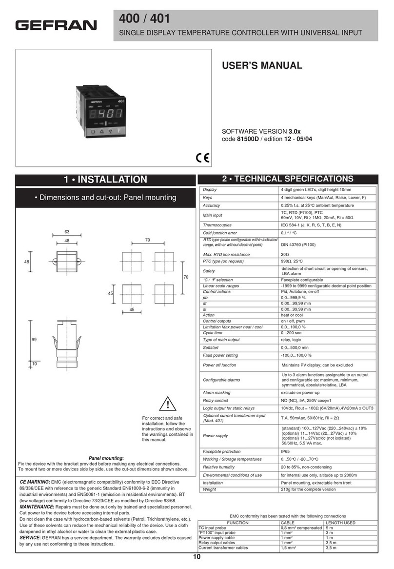
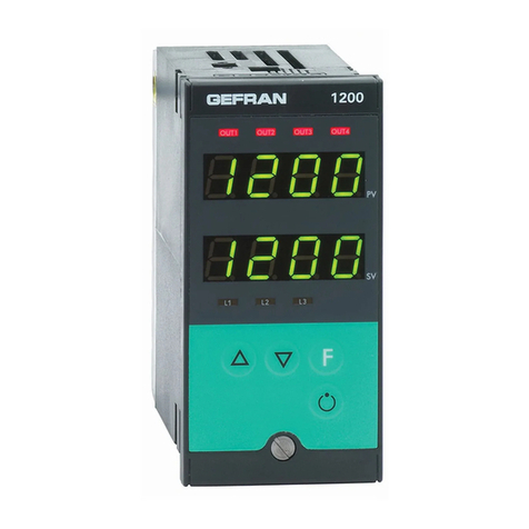
gefran 1000 User manual

1000 / 1001 / 1101
ISO 9001 SOFTWARE 11.x / 12.x
cod. 80343 / Edit. 11- 07/01
Italiano
TERMOREGOLATORI CONFIGURABILI - Manuale d’uso 2
English
CONFIGURABLE TEMPERATURE CONTROLLERS - User’s Manual 10
Deutsch
KONFIGURIERBARE TEMPERATURREGLER - Bedienungsanleitung 18
Français
THERMORÉGULATEURS CONFIGURABLES - Manuel d’Utilisation 26
Español
TERMORREGULADORES CONFIGURABLES - Manual de Uso 34
Portuguese
CONTROLADORES DE TEMPERATURA CONFIGURÁVEIS - Manual do Usuário 42

96
108 96
115
92
92
100
10
115
48
108 96
70
115
92
44,5
100
10
Per una corretta installazione applicare le avvertenze contenute nel manuale
1 • INSTALLAZIONE
• Dimensioni di ingombro e di foratura
2 •CARATTERISTICHE TECNICHE
!
2
1000 / 1001 / 1101
TERMOREGOLATORI CONFIGURABILI
Montaggio a quadro
Dimensioni frontali: 1000/1001
- 48x96mm/1.89"x3.78" (1/8DIN) Prof: 100mmí3.94"
Dimensioni foratura:
45(+0.6/-0)x92(+0.8/-0)mm/1.77"(+0.02/-0)x3.62"(+0.03/-0)
Per bloccare lo strumento inserire i due appositi blocchetti nelle sedi presenti sul lato inferiore e
superiore della scatola e serrare con le relative viti.
Per montare due o piùstrumenti affiancati, utilizzare i blocchetti di serraggio rispettando, per il foro,
le misure;
Affiancati:
Base (48 x n)-3/(1.89" x n)-0.11"
Altezza 92(+0.8/-0)/3.62"(+0.03/-0)
Incolonnati:
Base 45(+0.6/-0)/1.77" (+0.02/-0)
Altezza (96x n)-4(3.78"xn)-0.15 "dove "n" sta per numero degli strumenti.
Dimensioni frontali: 1101
- 96x96mm/3.78"x3.78" (1/4DIN) Profondità100mm./3.94"
Dimensioni foratura:
92(+0.8/-0)x92(+0.8/-0)mm./3.62" (+ 03/-0)x3.62"(+.03/-0).
Per bloccare lo strumento inserire i due appositi blocchetti nelle sedi presenti sul lato inferiore e
superiore della scatola e serrare con le relative viti.
Per montare due o piùstrumenti affiancati, utilizzare i blocchetti di serraggio rispettando, per il foro,
le misure;
Affiancati:
Base (96x n)-4/(3.78"x n)-0.15"
Altezza 92 (+0.8/0)/3.62"(+ 03/-0)
Incolonnati:
Base 92 (+0.8/-0)/3.62"(+.03/-0)
Altezza (96xn)-4/(3.78"xn)-0 15 "dove "n" sta per numero degli strumenti.
INGRESSI
Precisione 0,5% f.s. ± 1 digit
Tempo di campionamento 120msec
TC- Termocoppia
per strumento 1000
J(Fe-CuNi) 0...800°C / 32...999°F
K(NiCr-Ni) 0...999°C / 32...999°F
N(NiCr-Si-NiSi) 0...999°C / 32...999°F
S(Pt10Rh-Pt) 0...999°C / 32...999°F
R(Pt13Rh-Pt) 0...999°C / 32...999°F
T(Cu-CuNi) -100...400°C / -148...752°F
per strumenti 1001, 1101
J(Fe-CuNi) 0...800°C / 32...999°F
K(NiCr-Ni) 0...1300°C / 32...1999°F
N(NiCr-Si-NiSi) 0...1300°C / 32...1999°F
S(Pt10Rh-Pt) 0...1600°C / 32...1999°F
R(Pt13Rh-Pt) 0...1600°C / 32...1999°F
T(Cu-CuNi) -100...400°C / -148...752°F
Selezione tramite tastiera.
Errore sulla compensazione della temperatura ambiente
0,05°C per ogni 1°C di variazione. Messagi di fuori scala infe-
riore, superiore, di inserzione non corretta e di sonda aperta.
RTD 2/3 fili
per strumento 1000
Pt100 -19,9...99,9°C / -19,9...99,9°F
Pt100 -199...400°C / -199...752°F
RTD 2/3 fili
per strumenti 1001, 1101
Pt100 -199,9...199,9°C / -199,9...199,9°F
Pt100 -200...400°C / -328...752°F
DC - Lineari
0...50mV, 10...50mV Impedenza di ingresso > 1MΩ
Per segnali 0...10V, 0...20mA, 4...20mA utilizzare solo con
shunt esterni allo strumento.
USCITE
Uscita principale (MAIN) con funzione diretta (riscaldamento),
inversa (raffreddamento).
Relè
Con contatti 5A/250Vac a cosϕ= 1 (3,5A a cosϕ= 0,4);
Protezione spegniarco sui contatti NO. (Indicato in sigla con
R0);
Logica
22Vdc, Rout = 470Ω(20mA, max. 12V).
Protezione sulla inversione di polaritàe sui cortocircuiti.
Continua
0...20mA o 4...20mA su resistenza max. 500Ωconfigurabile in
0...10V con impedenza di 500Ω.
Resistenza di carico ≥47KΩ. (indicato in sigla con V e I)
LINEA SERIALE
Optoisolata 4 fili. Interfaccia disponibile Current Loop Passiva
(1200 baud) o RS485 4 fili (1200/2400/4800/9600 baud).
Protocollo: GEFRAN CENCAL
ALIMENTAZIONE
Standard: 100...240Vac/dc ± 10%
a richiesta: 11...27Vac/dc ± 10% 50/60Hz; 6VA max.
Protezione tramite fusibile interno non sostituibile dall’operatore.
REGOLAZIONE
Regolazione tipo On/Off, P, PD, PID sia in riscaldamento che
in raffreddamento, con parametri impostabili da tastiera:
•Banda proporzionale: 0,0...99,9% f.s.
•Tempo azione integrale: 0,0...99,9 min
•Tempo azione derivativa: 0,0...9,99 min (0,0...19,99 min)
•Potenza di reset (posizionamento della banda proporzionale):
0...100%.
•Isteresi (solo per regolazione On/Off): -199...999 (-
999...1999) digit.
•Tempo di ciclo: -2...200 sec (0 per regolazione On/Off).
•Soft-start (erogazione graduale dell’uscita principale, all’accen-
sione dello strumento, per un tempo impostato): 0...99,9 min
•Reset manuale (correzione della regolazione a regime):
-199...999 (-999...1999) digit.
•Offset (impostazione di una differenza fissa tra la lettura reale
della sonda d’ingresso e il valore “letto”dal regolatore):
-199...300 (-300...300) digit.
- Funzione Automatico/Manuale con bumpless al passaggio in
automatico.
- Funzione Accensione/Spegnimento software per disattivare
lo strumento.
ALLARMI
•3 soglie di allarme impostabili in valore assoluto, relativo,
relativo simmetrico rispetto al set-point con funzione invertibile
(diretto, inverso).
•Impostazione del punto di allarme sull’intera scala seleziona-
ta.
•Allarme (AL1) con uscita PD con parametri impostabili.
- Banda proporzionale impostata su isteresi di AL1:
-199...999 (-999...1999) digit.
- Tempo derivativo: 0,0...9,99 (0,0...19,99)min.
- Tempo di ciclo: 1...200 sec (0 per allarme On/Off).
•Allarme (AL3) utilizzabile come funzione di carico interrotto
(HB) abbinato all’ingresso da trasformatore amperometrico;
scala in corrente configurabile. 0...99,9 (0...199,9)
•Selezione allarme con uscita LBA (anello di regolazione aperto).
•Tempo di intervento e potenza erogata in situazione di allarme
LBA impostabili.
•Isteresi di intervento allarmi (impostabile nel campo):
-199...999 (-999...1999) digit.
CONDIZIONI AMBIENTALI
Temperatura di lavoro: 0...50°C
Temperatura di stoccaggio: -20...70°C
Umidità: 20...85%Ur non condensante
PESO : 320g (1000) 400g (1001, 1101)

3 •DESCRIZIONE FRONTALE STRUMENTO
3
4 •CONNESSIONI
A- Altezza cifre 14mm (1000), 10mm (1001), 20mm (1101) di colore verde
Valore della variabile regolala a 3 digit (1000) 31/2 digit (1001 -1101)
Indicazione - 199...+999 (1000) indicazione -999...+1999 (1001-1101) con punto
decimale nelle scale previste.
Segnalazione di Fuori scala positivo ( Hl ) o negativo ( LO ) Indicazione di rottura ed
errato collegamento della sonda; (SBR: sonda interrotta / ERR: sonda invertita) e
visualizzazione messaggi di configurazione e calibrazione.
B- Altezza cifre 14mm (1000), 10mm (1001), 14mm (1101) di colore verde
Valore setpoint.
Valore soglia allarme nel campo -199...+999 (1000) -999...+1999 (1001-1101).
I valori delle soglie di allarme sono accompagnati dal lampeggio del rispettivo LED
AL 1 AL2 AL3/HB. Valore uscita MAIN in percentuale (0...99%) seguito dalla lettera P.
Valore parametri e dati di configurazione.
C- Pulsante Funzione
Pernette di accedere alle funzioni di setpoint e di allarrne (ogni funzione é
specificata dal lampeggio del relativo LED per la lettura e/o la rnodifica dei relativi
valori.
Se il pulsante F non épremuto a conferma di una modifica, dopo 10 sec. Ia
rnemorizzazione avverràautomaticamente e la visualizzazione torneràal valore del
setpoint.
Con il tasto F si accede alle diverse fasi di configurazione e di memorizzazione delle
modifiche di impostazione.
D- Pulsante Incrementa / E- Pulsante Decrementa
Consentono un incremento o un decremento del valore della funzione visualizzata
sul display. La velocitàdi incrermento (decremento) éproporzionale alla durata
della pressione del tasto. L’operazione non éciclica. Raggiunto il massimi (minimo)
del campo di impostazione con tasto premuto, la funzione di incremento
(decremento) ébloccata.
F- Indicazione uscita principale attiva, led di colore verde
G- Segnalazione allarmi, led di colore rosso
Protezione frontale IP54 (disponibile IP65)
B
E
GF
D
A
C
B
E
GF
D
A
C
GF
B
ED
A
C
NC
C
NO
NC
C
NO
C
NO / NC
C
NO / NC
LINEA
SERIALE
PWR
ALIMENTAZIONE
TC Pt100
3 fili PTC
Pt100 2 fili
Ingresso amperometrico da TA 5Aac
MAIN
(D2)
MAIN
USCITA DI
CONTROLLO
CONTINUA
AL2
AL3/HB
AL1
Sono disponibili 21 attacchi per terminali faston da 6.35mm.
Ingressi di segnale
Gli ingressi da TC, o RTD 2 fili sono da applicare al faston 1 (positivo) e 3 (negativo)
(Cortocircuitare 3 e 4 nel caso di RTD a 2 fili.
Per RTD a 3 fili. il filo singolo va collegato al faston 1, dei rimanenti uno andràal faston 3 e
l'altro al 4.
Ingresso da trasformatore amperometrico (funzione HB)
Se lo strumento épredisposto, il segnale va applicato ai faston 6 e 7; ingresso secondario
arnperometrico per TA, impedenza 20mΩ, 5A, 50/60Hz.
Alimentazione
La tensione di alimentazione (100...240Vac) èapplicata ai faston o morsetli 12 e 14. E' dispo-
nibile la versione con tensioni 11...27Vac/dc.
Fusibile
E’interno allo strumento, non èsostituibile dall’operatore.
Alimentazione Tipo Corrente Tensione
100...240Vac T 0,5A 250V
11...27V T 1,25A 250V
Uscita principale
Uscita a reléai morsetti o faston 19 (N.O ) 18 (C) e 17 (N.C.); portata contatti 5A/250Va.c. a
cosϕ= 1
L’uscita logica tipo D2 24V/20mA max. édisponibile ai faston 16 (positivo) e 15 (negativo).
Uscita continua ai morsetti o faston 19 (+) e 17 (-) in alternativa all’uscita a relé.
Uscite di allarme
Per relédi allarme sono disponibili:
morsetti o faston 20 (N.C.) 21 (C) e 22 (N.O) per l’allarme 1; morsetto Faston11 e 10 (N.C. o
N.O.) per l’allarme 2; morsetti 9 e 8 (N.C. o N.O.) per allarme 3/HB.
Per gli allarmi 2 e 3 variando i ponticelli, sono disponibili anche i contatti N.C. La portata dei
contatti édi 5A per allarme 1 e 3A/250Va.c. per allarrni 2 e 3.
Comunicazione digitale (Current loop / 485)
Se lo strumento épredisposto per interfaccia Current loop passiva 1200 baud, il diodo di rice-
zione édisponibile ai faston 8 (Rx+) e 9 (Rx-); il transistor di trasmissione ai faston 10 (Tx+) e
11 (Tx-).
In configurazione standard per collegamento parallelo sulla linea seriale la resistenza in serie
al diodo é1 KOhm quella sul collettore del transistor é100 Ohm.
Per il collegamento serie la resistenza in serie al diodo é100 Ohm. Se lo strumento épredi-
sposto per interfaccia RS485 quattro fili 1200...9600 baud la ricezione édisponibile al faston 8
(Rx+) e 9 (Rx-); la trasmissione ai faston 10 (Tx+) e 11 (Tx-). (Vedi configurazione hardware).

5 •CONFIGURAZIONE HARDWARE
6 •MODO OPERATIVO
4
Scheda Ingressi
Protezione Hardware
Per estrarre la parte elettronica dalla custodia agire sulla vite frontale fino allo sblocco, quindi estrarre a mano. La configurazione si effettua sulla scheda di ingresso, di uscita / ali-
mentazione e sulla schedina opzionale.
Scheda ingressi
Sulla scheda ingressi sono posizionati i ponticelli per l’abilitazione/disabilitazione della configurazione e calibrazione
come descritto nella seguente tabella:
Descrizione Posizionamento Ponticelli a
ponticello stagno
(lato comp) (lato sald)
Config. abilitata 3 3 chiuso *
Config. disabilitata 7 oppure 8 3 aperto *
Calibraz. abilitata 6 6 chiuso *
Calibraz. disabilitata 7 oppure 8 6 aperto *
* ponticello lato saldature alternativo al posizionamento ponticello lato componenti.
Lo strumento éfornito con configurazione e calibrazione disabilitate.
L’ingresso da sonda RTD Pt100 (tipo 11) prevede i ponticelli S3 aperlo, S9 chiuso.
Opzionale allarmi 2 e 3
Selezione contatti N.O./N.C. relé2/3 di allarme
Normalmente gli allarmi 2 e 3, sono forniti N.O.; per avere la versione N.C,. énecessario rimuovere manualmente i
rispettivi ponticelli N.O. ed effettuare quelli N.C. (Ponticelli S10/S11, rispettivamente S12/S13 nella scheda ingressi, lato
saldature).
Scheda uscita/alimentazione
Uscita principale D2
Quando si utilizza l'uscita D2 éconsigliabile escludere l’attivitàdel relédi MAIN togliendo manualmente il ponticello S1.
Per ottenere l’uscita in tensione nel caso di uscita continua effettuare il ponticello V
Uscita Seriale RS485 (cod. 2 in sigla di ordinazione)
La linea seriale RS485 puòessere polarizzata eseguendo i pontlcelli di stagno S5 S6 e S7 presenti sul lato saldature
della scheda.
La distanza di trasmissione coperta dall'uscita seriale RS422/RS485 degli strumenti raggiunge i 500 metri con un massl-
mo dl 32 strumenti collegati. Per lunghezza di linea maggiore di 50 metri e nei casi in cui si rende necessaria un'impe-
denza per la terminazione della linea questa édisponibile internamente allo strumento.
La terminazione dovràessere effettuata internamente allo strumento che risulta essere il piùlontano nella catena del col-
legamento seriale
Schedina opzionale uscita controllo MAIN continua
Per uscita in tensione eflettuare il ponticello indicato V.
(Vedi scheda uscita alimentazione)
Scheda Uscita Alimentazione
Scheda Opz. Seriale C.L. Scheda Opzionale RS485 Scheda Opz. Uscita controllo MAIN continua
Premessa
Il modo operativo permette il monitoraggio delle principali grandezze del processo:
variabile di processo, corrente di carico, potenza in uscita di regolazione, mentre lo
stato delle uscite (MAIN e allarmi) ésegnalato dai rispettivi led. Inoltre permette la
visualizzazione e l'impostazione del setpoint di regolazione e degli allarmi.
La scansione delle sette fasi operative (v. tabella sottostante) avviene per mezzo del
tasto F. Per impostare il setpoint e gli allarmi si usano i tasti Incrementa e
Decrementa. Una pressione prolungata del tasto aumenta la velocitàdi variazione del
valore. La conferma del valore impostato avviene premendo F oppure automaticamen-
te dopo 10 secondi dall'ultima modifica.
L'abilitazione delle varie fasi dipende dalla configurazione hardware e software e del
livello di protezione software impostato (codice Pro in fase CFG.2). In configurazione
minima sono disponibili solo le fasi 0 e 1.
Al power-on, finito il lampeggio del display, lo strumento si predispone nella fase 0 del
modo operativo (partenza in automatico), oppure nella fase 6 (partenza in manuale).
Determinate combinazioni di tasti permettono di commutare tra automatico e manuale,
di effettuare lo spegnimento e l'accensione software, di avviare o di interrompere il self-
tuning. Il modo operativo éil punto di partenza per l'accesso alle fasi di
Programmazione, Configurazione e Calibrazione.
Visualizzazione variabile di processo, corrente di carico, potenza in uscita.
Impostazione setpoint e allarmi
Funzione AUTO/MAN
Funzione Accensione/Spegnimento software
Start/Stop selftuning
Versione software
Messaggi di errore e segnalazioni
Power on
Sequenza delle fasi in modo operativo
Fase oper. Display superiore Display inferiore Segnalazione fase Note
0 Variabile processo Setpoint regolazione* Nota 1
1 Variabile processo Soglia allarme 1 * Led AL1 lampeggiante Nota 2
2 Variabile processo Soglia allarme 2 * Led AL2 lampeggiante Nota 2
3 Variabile processo Soglia allarme 3 * Led AL3 lampeggiante Nota 2
4 Valore ingresso TA Soglia allarme HB * Lettera A lampeggiante Nota 3
5 Variabile processo Valore ingresso TA Lettera A fissa Nota 4
6 Variabile processo Pot. Auto/Man in uscita Lettera P fissa/lamp. Nota 5
* valore impostabile, ritorno dopo 10 secondi nella fase operativa 0.

5
6 •MODO OPERATIVO
Note:
1. Fase operativa 0 (SP)
In funzionamento normale il display superiore visualizza la variabile di processo PV
(misurata in ingresso) mentre quello inferiore il setpoint di regolazione. Una modifica
del setpoint diventa immediatamente operativa.
2. Fasi operative 1,2,3 (allarmi)
L'allarme 1 ésempre abilitato. La presenza degli allarmi 2 e 3 dipende dal valore del
codice brd (in CFG2) che rispecchia la configurazione hardware. Se uno dei tre allarmi
éconfigurato come HB (vedi codice A.r.F. in CFG2) compariràla fase 4 al posto delle
fasi 1,2 o 3 con il rispettivo led lampeggiante. Se éconfigurato come LBA, la rispettiva
fase non compare. Vedi Note di funzionamento/Allarmi.
3.Fase operativa 4 (allarme HB)
E' abilitata soltanto se lo strumento monta l'ingresso TA (v. codice brd) e se l'allarme
HB éabilitato (v. codice Out in CFG2). Viene segnalata dal lampeggio della lettera "A"
sul digit meno significativo del display inferiore. I digit piùsignificativi visualizzano il
valore intero della soglia HB mentre il display superiore visualizza il valore della corren-
te nel carico letto dall'ingresso TA in Amper (risoluzione 0.1 Amper). Premendo i tasti
Incrementa o Decrementa al posto della lettera A compare la cifra decimale della
soglia che permane durante la modifica. A tasti rilasciati la "A" ricompare dopo 1
secondo.
Premendo F si conferma il valore impostato e si passa alla fase successiva. Vedi Note
di funzionamento/Allarmi/HB Alarm.
4. Fase operativa 5 (ingresso TA)
E' abilitata soltanto se lo strumento monta l'ingresso TA (v. codice brd) ed éind!pen-
dente dall'allarme HB. Il display inferiore visualizza la parte intera del valore della cor-
rente nel carico, seguito dalla lettera "A" fissa. Permane sul display a tempo indetermi-
nato. Vedi Note di funzion./Funzione Ingresso TA.
5. Fase operativa 6 (POWER)
E' accessibile solo con la funzione AUTO/MAN abilitata (v. codice brd in fase CFG.2).
La descrizione dettagliata della funzione AUTO/MAN si trova nel capitolo Note di fun-
zionamento/Funzione AUTO/MAN.
Commutazione AUTO/MAN e MAN/AUTO
In fase operativa 6, premendo insieme i tasti Incrementa e Decrementa si commuta da
automatico in manuale. Premendo F si commuta da manuale in automatico. ("P" fissa
in automatico, lampeggiante in manuale). In manuale épossibile variare la potenza in
uscita direttamente per mezzo dei tasti Incrementa e Decrementa. Vedi nel capitolo
Note di funzionamento
Start/stop selftuning
La combinazione dei tasti F e Incrementa premuti per 3 secondi permette di attivare la
procedura di selftuning. Stesso comando per interrompere la procedura in svolgimento.
Vedi Note di funzionamento / SELFTUNlNG.
Spegnimento/Accensione software
Premendo insieme i tasti F e Decrementa per 5 secondi lo strumento passa in stato di
OFF (display spento, uscite disatti vate). Premendo F per 5 secondi lo strumento si
"attiva". Vedi l'omonimo capitolo in Note di funzionamento.
Visualizzazione numero versione software
Tenendo premuto il tasto "F" per 3 secondi sul display supe riore compare la scritta
Upd e sul display inferiore il numero della versione (release) software (es. Upd/11.0).
Al rilascio del tasto il display torna in modo operativo, fase 0.
Messaggi di errore e segnalazioni
Messaggio Sbr sul display superiore: sonda ingresso interrotta (TC-RTD) .
Messaggio Err sul display superiore: errato collegamento; sonda invertita (TC); sonda
in cortocircuito (RTD).
Messaggio Lo sul display superiore: fuori scala inferiore.
Messaggio Hi sul display superiore: fuori scala superiore.
Display superiore lampeggiante: selftuning o softstart in svolgimento. Display superiore
e inferiore lampeggiante: allarme LBA attivo. Due punti decimali (uno solo per scale
con punto decimale) lampeggianti sul display superiore: autotuning attivo. Punto deci-
male lampeggiante con il display spento: strumento in stato di "spegnimento" software
(OFF).
Plampeggiante sul display inferiore: fase operativa 6 modo MAN (potenza impostabile
da tastiera).
Pfissa sul display inferiore: fase operativa 6 modo AUTO (visualizzazione potenza in
automatico).
Alampeggiante sul display inferiore: fase operativa 4 imposta zione soglia allarme HB
A fissa sul display inferiore: fase operativa 5 visualizzazione ingresso amperometrico.
Led AL1, AL2, AL3 lampeggiante: fase di impostazione soglia allarme.
Led AL1, AL2, AL3 acceso: relédi allarme eccitato.
Led AL1, AL2, AL3 spento: relédi allarme diseccitato oppure allarme non abilitato.
Led MAIN acceso: uscita MAIN attiva (reléMAIN eccitato, uscita D2 livello logico 1)
Led MAIN spento: uscita MAIN inattiva (reléMAIN diseccitato, uscita D2 livello logico 0)
Led MAIN lampeggiante con elevata frequenza: uscita continua (LA) attiva.
Power on
All'accensione lo strumento esegue un ciclo di inizializzazione di 5 secondi durante il
quale le uscite sono disabilitate (relédiseccitati, uscite D2 e continua OFF) con il lam-
peggio di tutti i segmenti e i led del display. In seguito lo strumento si predi spone nella
fase operativa 0 (accensione in automatico) oppure 6 (accensione in manuale).
Per la durata del primo tempo di ciclo il filtro software sull'ingresso di segnale édisabili-
tato.
7 •PROGRAMMAZIONE
Premessa alle procedure di impostazione e configurazione
La programmazione avviene in 3 fasi:
0) Impostazione 1/2) Configurazione
L'accesso alle fasi épossibile tramite pulsante F.
Fase 0 / Impostazione
In funzionamento normale premere il pulsante F per 5 sec. per impostare i parametri:
_Pb_ / Banda Proporzionale nel campo 0.0...99.9% F S.
Se la regolazione édi tipo ON/OFF (tempo integrale, derivativo e di ciclo nulli), il valore
impostato definisce l'isteresi -199...+999 (1000) -19.9...+99.9 (1000 scala con punto
decimale) -999...+1999 (1001-1101) -99.9...+199.9 (1001-1101 scala con punto deci-
male).
_rSt _/: Reset manuale nel campo -199...+999 (1000) -19.9...+99.9 (1000 scala con
punto decimale) -999...+1999 (1001-1101) -99.9...+199.9 (1001-1101 scala con punto
decimale).
A regolazione assestata, porta il valore della grandezza regolata esattamente sul set-
point di impostazione (a volte éun'opera zione necessaria nella regolazione PD).
_Ct/: Tempo di Ciclo nel campo -2...200. Impostando Ct=0 il tempo di ciclo éescluso e
la regolazione diventa del tipo ON/OFF (in questo caso Pb diventa l'isteresi in punti
scala). Impostando Ct = -1 si ottiene l'uscita PWM veloce con il tempo di ciclo (duty
cycle) fisso di 100 millisecondi, utilizzabile solo con uscita D2 oppure con l'uscita conti-
nua 0...10V o 0...20mA. Impostare Ct = -2 per uscita continua 2...10V o 4...20mA) I
valori Ct = 1 a 200 sono da considerare come tempo di ciclo in secondi.
P.St/: Potenza di Reset nel campo 0 -100%. L' azione di Reset equivale al libero posi-
zionamento della Banda Proporzionale. Impostando 0 la P B. ésotto il setpoint; impo-
stando 100 la P.B. écompletamente sopra il setpoint (con l'uscita principale in
Funzione diretta). Nel caso di rego lazione ON/OFF la potenza di Reset impostata non
ha nessuna influenza.
S.tu/: Inserimento della funzione di Self e Auto-tuning seguendo la relativa tabella.
S.tu SELF AUTO SOFT-START
0NO NO NO
1NO SI NO
2SI NO NO
3SI SI NO
4NO NO SI
5NO SI SI
+8 per disabilitare il filtro software sulla variabile controllata (consigliato per le scale lineari)
Disabilitazione automatica del selftuning al termine del calcolo
_Lb.t/ Tempo di attesa per l'attivazione dell'allarme LBA (1 ..240 min); impostando 0 la
funzione LBA vlene dlsattivata.
_Lb.P/ Potenza fornita in condizione di allarme LBA attivo, impostabile nel campo
0...100%
Terminata l'impostazione premere il pulsante F per tornare al funzionamento normale
Fase 1 Contigurazione (CFG1)
Per accedere alla fase 1 premere il pulsante F fino a che compare sul display il mes-
saggio CFG1
_It/: Tempo Integrale nel campo 0.0...99.9 min (impostando 0.0 I'azione integrale é
esclusa). Ad un tempo integrale elevato corrisponde un'azione integrale blanda mentre
ad un tempo integrale breve corrisponde un'azione integrale incisiva
_dt/ Tempo Derivativo nel campo 0.00...9.99 mln (1000) 0.00...19.99 min (1001-1101)
(impostando 0.00 I'azione derivativa éesclusa) L'efficacia dell'azione derivativa
aumenta proporzionalmente con il tempo derivativo.
SOF/: Tempo di Soft-start nel campo 0.0...99.9 min (impostando 0.0 I'azione di Soft-
start éesclusa).
L'azlone dl Soft-start esaurisce nel tempo impostato o con la variabile controllata in
Banda Proporzionale.
Hy1/: Isteresi o Banda Proporzionale (PD) per AL1 nel campo -199 +999 digit (1000) -
19.9...+99.9 (1000 scala con punto decimale) -999...+1999 (1001-1101) -99.9...+199.9
(1001-1101 scala con punto decimale). Un numero negativo (o positivo) indica una
banda di isteresi, posizionata sotto (o sopra) la soglia di allarme ed écaratteristica di
un allarme diretto (o inverso).
Hy2/: Isteresi per AL2 nel campo -199.. +999 digit (1000) -19.9.. +99.9 (1000 scala con
punto decimale) -999...+1999 (1001 1101) -99.9...+199.9 (1001-1101 scala con punto
decimale).
Hy3/ Isteresi per AL3 nel campo -199...+999 digit (1000) -19.9...+99.9 (1000 scala con
punto decimale) -999...+1999 (1001-1101) -99.9...+199.9 (1001-1101 scala con punto
decimale).
Hb.s éselezionabile solo per strumenti dotati dell'ingresso da trasformatore ampero-
metrico (TA) Impostazione fondo scala di corrente da 0...199.9 (99.9).
no /Codice strumento per il collegamento in linea seriale nel campo 0...999; compare
solo per strumenti dotati di comunicazione seriale (versione 1 H), con l'apposita impo-
stazione del codice "brd" (vedi CFG2).
bAU/ Baud rate per la comunicazione seriale, secondo la tabella:
0 1200 baud CL, 485
1 2400 baud CL, 485
2 4800 baud 485
3 9600 baud 485
Édisponibile solo per strumenti che montano la schedina seriale con l'apposita impo-
stazione del codice "brd" (v. CFG.2)
N.B.: per la documentazione relativa al protocollo seriale fare riferirnento al manuale
"Introduzione alla comunicazione seriale".
FA.P/ Potenza di "fault action" nel campo 0-100%. Viene fornita in uscita MAIN in caso
di rottura sonda ingresso (segnalazione Sbr oppure Err sul display)

6
7 •PROGRAMMAZIONE
Fase 2 Configurazione (CFG2)
L'accesso alla fase CFG2 écondizionata dalla chiusura del ponticello 3 / J13 sulla
scheda CPU lato componenti (vedi Configurazione Hardware).
Pro/: Livello di protezione software nel campo 0-31 come tabella.
Pro Setpoint Allarmi Fase 0 It, dt CFG1
0DISPLAY <> DISPLAY <> DISPLAY <> DISPLAY <> DISPLAY <>
1DISPLAY <> DISPLAY <> DISPLAY <> DISPLAY <>
2DISPLAY <> DISPLAY <> DISPLAY <> DISPLAY <>
3DISPLAY <> DISPLAY <> DISPLAY <>
4DISPLAY <> DISPLAY <> DISPLAY <>
5DISPLAY <> DISPLAY <>
6DISPLAY <> DISPLAY
7DISPLAY DISPLAY
DISPLAY = VISUALIZZAZIONE <> = IMPOSTAZIONE
+8 per disabilitare la Funzione "spegnimento/accensione" (ON-OFF) da tastiera
+16 per inibire la funzione AUTO/MAN (solo per strumenti predisposti alla funzione
AUTO/MAN): rimane abilitata solo la visualizzazione della potenza in AUTOmatico.
Livello protezione standard 19. I parametri della Fase CFG2 non sono sottoposti alla
protezione software ( I'accesso alla fase CFG2 dipende solo dallo stato del jumper
3/J13(conf.HW).
_AI/: Funzione dell'uscita di allarme.
La configurazione di allarmi relativi simmetrici richiede l'impostazione dei valori di
soglia solo positivi, valori negativi non sono ammessi per una corretta funzionalità
anche se impostabili.
0= Allarmi 1 e 2 assoluti diretti (reléeccitato al superamento della soglia di allarme).
1= Allarme 1 relativo, Allarme 2 assoluto entrambi diretti.
2= Allarme 1 assoluto, Allarme 2 relativo entrambi diretti.
3= Allarme 1, Allarme 2 relativi diretti.
4= Allarme 1 assoluto inverso (reléeccitato alla discesa sotto la soglia di allarme),
Allarme 2 assoluto diretto.
5= Allarme 1 relativo inverso, Allarme 2 assoluto diretto.
6= Allarme 1 assoluto inverso, Allarme 2 relativo diretto.
7= Allarme 1 relativo inverso, Allarme 2 relativo diretto.
8= Allarme 1 assoluto diretto, Allarme 2 assoluto inverso.
9= Allarme 1 relativo diretto, Allarme 2 assoluto inverso
10 = Allarme 1 assoluto diretto, Allarme 2 relativo inverso.
11 = Allarme 1 relativo diretto, Allarme 2 relativo inverso.
12 = Allarme 1, Allarme 2 assoluti inversi.
13 = Allarme 1 relativo inverso, Allarme 2 assoluto inverso.
14 = Allarme 1 assoluto inverso, Allarme 2 relativo inverso.
15 = Allarme 1, Allarme 2 relativi inversi.
Aggiungendo 16 al codice di funzione selezionato (es. 9+16 impostazione 25) AL1
diventa relativo simmetrico: in questo caso ad un allarme diretto corrisponde un allar-
me con reléeccitato all'esterno della "finestra" mentre ad un allarme inverso corri-
sponde un allarme con reléeccitato all'interno.
Aggiungendo 32, AL2 diventa relativo simmetrico.
Aggiungendo 48, entrambi gli allarmi diventano relativi simmetrici.
Out/: Funzione di uscita principale (Risc/Raff) e AL1 (PD) abilitazione allarme HB e
selezione della scala di temperatura (°C o °F)
Impostare, come da tabella, il codice per la combinazione di funzioni scelta.
Nr. Al.HB AL1 OUT Scala Nr. Al.HB AL1 OUT Scala
0Disabilitato NO PD HEAT °C8Disabilitato NO PD HEAT °F
1Abilitato NO PD HEAT °C9Abilitato NO PD HEAT °F
2Disabilitato PD HEAT °C10 Disabilitato PD HEAT °F
3Abilitato PD HEAT °C11 Abilitato PD HEAT °F
4Disabilitato NO PD COOL °C12 Disabilitato NO PD HEAT °F
5Abilitato NO PD COOL °C13 Abilitato NO PD HEAT °F
6Disabilitato PD COOL °C14 Disabilitato PD HEAT °F
7Abilitato PD COOL °C15 Abilitato PD HEAT °F
Aggiungendo alle 16 combinazioni i 6 STEP sotto riportati,si possono ottenere varie
combinazioni per AL3.
+0 AL3 ASSOLUTO DIRETTO NORMALE
+16 AL3 RELATIVO DIRETTO NORMALE
+32 AL3 ASSOLUTO INVERSO NORMALE
+48 AL3 RELATIVO INVERSO NORMALE
+80 AL3 RELATIVO DIRETTO FINESTRA*
+112 AL3 RELATIVO INVERSO FINESTRA*
Con impostazione soglia AL3 = 0 oppure negativo AL3 rimane eccitato o diseccitato sempre.
Note: L'allarme PD non puòessere del tipo simmetrico.
TyP/ Tipo di sonda o della scala lineare di ingresso.
Cod. 1000 1001/1101
0 J 0...800°C/32...999°F J 0...800°C/32...1472°F
1 K 0...999°C/32...999°F K 0...1300°C/32...1999°F
2 N 0...999°C/32...999°F N 0...1300°C/32...1999°F
3 S 0...999°C/32...999°F S 0...1600°C/32...1999°F
4 R 0...999°C/32...999°F R 0...1600°C/32...1999°F
5 T -100...400°C/-148...752°F T -100...400°C/-148...752°F
6 PT100 -199...400°C/-199...752°F PT100 -200...400°C/-328...752°F
7 PT100 -19,9...99,9°C/-19,9...99,9°F PT100 -199,9..199,9°C/ -199,9..199,9°F
8 0-50mV no decimali (xxx) 0-50mV no decimali (xxxx)
9 0-50mV 1 decimali (xx.x) 0-50mV 1 decimali (xxx.x)
10 0-50mV 2 decimali (x.xx) 0-50mV 2 decimali (xx.xx)
11* PT100 -19,9...99,9°C/-3,8...99,9°F PT100 -19,9...199,9°C/-3,8...199,9°F
12 10-50mV no decimali (xxx) 10-50mV no decimali (xxxx)
13 10-50mV 1 decimali (xx.x) 10-50mV 1 decimali (xxx.x)
14 10-50mV 2 decimali (x.xx) 10-50mV 2 decimali (xx.xx)
* Versione hardware per ingresso RTD con doppia risoluzione per consentire una maggiore
stabilitàdel decimo di grado.Tale versione non permette la riconfigurazione del tipo di ingres-
so. Per le sonde TC tipo S ed R si segnala che la precisione rientra nella classe dello stru-
mento (0,5%) per valori di temperatura >200°C
Ct.A / Tempo di Ciclo AL1 nel campo 0...200 sec.
dt.A / Tempo Derivativo AL1 nel campo 0.00...9.99 min. (1000)
0.00...19.99 min (1001-1101).
oFt / Aggiustamento Offset ingresso
per strumenti 1001/1101:
-300/300 per tipo 0,1,2,3,4,5,6,8
-30.0/30.0 per tipo 7,9,11
-3.00/3.00 per tipo 10
perstrumenti 1000:
-199/300 per tipo 0,1,2,3,4,5,6,8
-19.9/30.0 per tipo 7,9,11
-1.99/3.00 per tipo 10
LO.S / Valore minimo del set-point e degli allarmi assoluti nel campo scala della
sonda selezionata Inizio scala lineare per sonda tipo 8, 9, 10, 12, 13, 14
Hl.S / Valore massimo del set-point e degli ailarmi assoluti nel campo scala della
sonda selezionata Fondo scala lineare per sonda tipo 8,9,10, 12, 13, 14.
rEL/ Impostazione dello stato delle uscite di allarme in caso di rottura sonda (messag-
gio Sbr/Err sul display), secondo la tabella:
rEL Uscita AL1 Uscita AL2 Uscita AL3
0ONONON
1ONONOFF
2 OFF ON ON
3 OFF ON OFF
4 ON OFF ON
5 ON OFF OFF
6 OFF OFF ON
7 OFF OFF OFF
Nota: In caso di rottura sonda ogni relé assume lo stato impostato (ON = eccitato, OFF =
diseccitato), il quale non dipende dal tipo di allarme (diretto o inverso).
A.r.F/ Selezione della funzione delle uscite di allarme.
Permette di assegnare ad ognuna delle uscite di allarme una delle funzioni: Allarme
Normale, Allarme HB, Allarme LBA, Allarme disabilitato (stato logico di OFF).
Scegliere una delle 63 combinazioni secondo la tabella:
Ar.F Uscita AL1 Uscita AL2 Ar.F Uscita AL1 Uscita AL2
0 AL1 AL2 8 AL1 LBA
1 HB AL2 9 HB LBA
2 LBA AL2 10 LBA LBA
3 OFF AL2 11 OFF LBA
4 AL1 HB 12 AL1 OFF
5 HB HB 13 HB OFF
6 LBA HB 14 LBA OFF
7 OFF HB 15 OFF OFF
Impostando +0 uscita AL3 ha la funzione AL3
Impostando +16 uscita AL3 ha la funzione HB
Impostando +32 uscita AL3 ha la funzione LBA
Impostando +48 uscita AL3 sempre OFF

7
7 •PROGRAMMAZIONE
Note:
- Lo stato dell'uscita puòessere invertito impostando il rispettivo allarme di tipo inverso (codi-
ce AL per le uscite AL1 e AL2 e codice Out per l'uscita AL3, in fase CFG.2)
- La selezione per le uscite AL2 e AL3 éinoperante in caso di configurazione tipo "relénon
presente" (v. codice brd)
- La funzione "ArF" éprioritaria rispetto alla funzione "Out".
Ctr/ Selezione tipo di controllo PID e le modalitàdi passaggio da automatico in manua-
le secondo la tabella:
Ctr Controllo PID per: Passaggio da Autom/Manual
0 Processo lento (ts=8sec) con potenza man. memorizzata
1 Processo veloce (ts=1sec) con potenza man. memorizzata
2 Processo lento (ts=8sec) con potenza autom. attuale
3 Processo veloce (ts=1sec) con potenza autom. attuale
Note:
ts - tempo di sample della azioni I e D
Per processo veloce si intende un processo con la costante di tempo principale minore
di 60 secondi. E' consigliabile la disabilitazione del filtro digitale sull'ingresso in caso di
selezione PID per processi veloci (vedi codice S.tu in fase 0).
Hb.F/ Selezione del tipo dell'allarme HB tra 4 diverse possibilità:
0- allarme attivo all'abbassamento della corrente di carico
(ingresso TA) sotto la soglia impostata nel tempo di ON dell'uscita MAIN
1- allarme attivo al superamento del valore di 12% del fondo scala amperometrico
(Hb.S) nel tempo di OFF dell'uscita MAIN
2- allarme attivo se una delle funzioni 0 e 1 (descritte sopra) éattiva. (OR logico tra le
funzioni 0 e 1)
3- allarme HB per uscita continua (PWM, impostazione _Ct = -1 o -2); non tiene conto
dei tempi di ON/OFF e presuppone una schedina amperometrica speciale con integra-
zione hw.della corrente di carico.
Note:
- il codice Hb.F éaccessibile solo con la schedina ingresso amperometrico montata
(vedi codice brd) e allarme HB abilitato (codice Out in CFG.2)
- vedi anche capitolo FUNZIONAMENTO DEGLI ALLARMI / HB ALARM
brd/ Codice del modello hardware e abilitazione funzione automatico / manuale (A/M)
brd Display A/M ReléAL2 ReléAL3
0 3 digit disabilitato non installato non installato
2 4 digit disabilitato non installato non installato
4 3 digit abilitato non installato non installato
6 4 digit abilitato non installato non installato
8 3 digit disabilitato installato non installato
10 4 digit disabilitato installato non installato
12 3 digit abilitato installato non installato
14 4 digit abilitato installato non installato
16 3 digit disabilitato non installato installato
18 4 digit disabilitato non installato installato
20 3 digit abilitato non installato installato
22 4 digit abilitato non installato installato
24 3 digit disabilitato installato installato
26 4 digit disabilitato installato installato
28 3 digit abilitato installato installato
30 4 digit abilitato installato installato
Aggiungendo 64 al codice si configura il modello con l'ingresso da trasformatore ampe-
rometrico.
Aggiungendo 128 al codice si configura il modello con la comunicazione seriale CL o 485.
Note:
- Le configurazioni selezionate devono essere conformi con il modello hardware dello stru-
mento. Una selezione errata puo causare funzionamento non conforme alle specifiche.
- La modifica del codice brd épossibile soltanto con il ponticello 6 chiuso
(Configurazione Hardware / Scheda Ingressi).
- ll codice brd édisponibile anche in fase di calibrazione.
8 •CALIBRAZIONE
Abilitare la configurazione e la calibrazione come descritto nel manuale al capitolo
Configurazione hardware (ponticelli "3" e "6" chiusi).
Impostare in fase CFG/2 (Configurazione 2) il tipo di sonda di ingresso desiderata:
parametro tyP:
tyP = 0,1,2,3,4,5 per termocoppie J,K.N.S R,T
tyP = 6,7 per termoresistenze Pt100
typ = 8,9,10 per ingresso lineare 0 ..50mV
typ = 12,13,14 per ingresso lineare 10 ..50mV
tyP = 11 per termoresistenze Pt100 scala speciale -19.9. .99.9 (199.9)°C con
modifica hardware.
Uscire dalla fase CFG/2; lo strumento torna in funzionamento normale. Procedere alla
calibrazione con lo strumento acceso almeno da 5-10 minuti. Eseguire la procedura di
calibrazione come segue:
A) Calibrazione termocoppie J,K,N,S,R,T e ingresso lineare 0-50mV10-50mV.
A.1) Tenere premuto il tasto F fino alla comparsa sul display della scritta CAL; rilascia-
re F
A.2) Collegare un segnale di 50.00mV da un calibratore tra i morsetti 1 (+) e 3 (-).
A.3) Premere F: il display mostra il messaggio CAL/50; aspettare circa 6 secondi.
A.4) Premere F: il display mostra il messaggio t.A/25.0; con i tasti incrementa e decre-
menta impostare il valore reale della temperatura dell'ambiente nel quale si esegue la
procedura dl callbrazione (esempio: t.A = 23.7°C). Per ingressi lineari non énecessario
impostare la temperatura ambiente
A.5) Premere F: il display mostra brd/valore; impostare il codice del modello hardware
(v. tabella brd in fase CFG.2).
A.6) Premere F per concludere la procedura di calibrazione; lo strumento torna in fun-
zionamento normale.
Se permane il segnale di 50mV in ingresso, il display mostra il messaggio _Hi per tyP
= 0,1,2,3,4,5 (termocoppie) oppure il massimo scala per tyP = 8,9,10,12,13,14 (scala
lineare). A questo punto l'ingresso termocoppia e lineare écalibrato.
B) Calibrazione ingresso termoresistenza Pt100 2/3 fili (tyP =6 oppure 7).
B.1) Tenere premuto il tasto F fino alla comparsa sul display della scritta CAL rilasciare F
B.2) Premere F; il display mostra il messaggio CAL/18; collegare tra i morsetti 1 e 3
una resistenza da 18.49 Ohm oppure un segnale da calibratore pari a -200.0°C, corto-
circuitare i morsetti 3 e 4; aspettare circa 10 secondi
B.3) Premere F: il display mostra il messaggio CAL/250; collegare tra i morsetti 1 e 3
una resistenza da 250.00 Ohm oppure un segnale da calibratore pari a +408.6°C; si
deve mantenere il corto tra i morsetti 3 e 4; aspettare circa 10 secondi.
B.4) Premere F: il display mostra brd/valore; impostare il codice del modello hardware
(v. tabella brd in fase CFG 2).
B.5) Premere F per concludere la procedura di calibrazione; lo strumento torna in fun-
zionamento normale. Se permane la resistenza da 250 Ohm in ingresso, il display
mostra il messagglo _Hi. A questo punto l'ingresso Pt100 écalibrato.
C) Calibrazione ingresso termoresistenza Pt100 2/3 fili scala speciale (tyP = 11)
Prima di procedere alla calibrazione assicurarsi che l'hardware dello strumento sia pre-
disposto per questo tipo di ingresso.
C.1) Tenere premuto il tasto F fino alla comparsa sul display della scritta CAL; rilasciare
F
C.2) Premere F; il display mostra il messaggio CAL/92; collegare tra i morsetti 1 e 3
una resistenza da 92.16 Ohm oppure un segnale da calibratore pari a -20.0°C; corto-
circuitare i morsetti 3 e 4; aspettare circa 10 secondi.
C.3) Premere F; il display mostra il messaggio CAL/175; collegare tra i morsetti 1 e 3
una resistenza da 175.84 Ohm oppure un segnale da calibratore pari a +200.0°C; si
deve mantenere il corto tra i morsetti 3 e 4; aspettare circa 10 secondi.
C.4) Premere F: il display mostra brd/valore; impostare il codice del modello hardware
(v. tabella brd in fase CFG 2).
C.5) Premere F per concludere la procedura di calibrazione; lo strumento torna in fun-
zionamento normale. Se permane la resistenza da 175.84 Ohm in ingresso, il display
mostra il messaggio _Hi per il modello 1000 e il valore 199,9 per i modelli 1001,1101.
A questo punto l'ingresso Pt100 écalibrato.
D) Calibrazione ingresso TA (amperometrico) per l'allarme HB.
La procedura éabilitata solo se l'hardware épredisposto (vedi codice brd in CFG.2).
D.1) Tenere premuto il tasto F fino alla comparsa del messaggio Hb.C sul display
superiore. Collegare tra i faston 6 e 7 un segnale di 5A corrente alternata.
D.2) Premere il tasto F: il display mostra il messaggio Hb.C/5; aspettare circa 6 secondi.
D.3) Premere il tasto F per concludere la procedura di calibra zione ingresso TA; lo
strumento torna in funzionamento normale. Se permane la corrente di 5A in ingresso
TA, il valore di corrente (accessibile col tasto "F") mostreràil fondo scala impostato
(parametro Hb.S in fase CFG/1). A questo punto l'ingresso TA écalibrato.
9 •AZIONI DI CONTROLLO
Azione Proporzionale: azione in cui il contributo sull'uscita éproporzionale alla deviazione
in ingresso (Deviazione élo scostamento fra variabile regolata e valore desiderato).
Azione Derivativa: azione in cui il contributo sull'uscita éproporzionale alla velocitàdi
variazione della deviazione in ingresso.
Azione Integrale: azione in cui il contributo sull'uscita éproporzionale all'integrale nel
tempo della deviazione di ingresso.
Influenza delle azioni Proporzionale, Derivativa ed Integrale sulla risposta del
processo sotto controllo.
•L'aumento della Banda Proporzionale riduce le oscillazioni ma aumenta la deviazione.
•La diminuzione della Banda Proporzionale riduce la deviazione ma provoca oscillazio-
ni della variabile regolata (valori troppo bassi della Banda Proporzionale rendono il
sistema instabile)
•L'aumento dell'Azione Derivativa, corrispondente ad un aumento del Tempo Derivati-
vo, riduce la deviazione ed evita oscillazioni fino ad un valore critico del Tempo Deriva-
tivo oltre il quale aumenta la deviazione e si verificano oscillazioni prolungate.
•L'aumento dell'Azione Integrale, corrisponde ad una diminuzione del Tempo Integrale,
tende ad annullare la deviazione a regime fra variabile regolata e valore desiderato
(set-point).
Se il valore del Tempo Integrale étroppo lungo (Azione Integrale debole) épossibile
una persistenza della deviazione tra variabile regolata e valore desiderato.
In tal caso éopportuno ridurre la Banda Proporzionale ed aumentare l'Azione Derivati-
va e Integrale fino al risultato voluto.

8
10 •NOTE DI FUNZIONAMENTO
•FUNZIONE ACCENSIONE-SPEGNIMENTO SOFTWARE
Come spegnere: tramite la combinazione di tasti "F" e "Decrementa" premuti insieme per
5 secondi épossibile disattivare lo strumento, che si predispone in stato di "OFF" assu-
mendo un comportamento simile allo strumento spento, senza togliere l'alimentazione di
rete. Durante lo stato di "OFF" il display éspento, con il puntino decimale lampeggiante
sul secondo digit del display inferiore che indica la presenza della tensione di rete; tutte le
uscite (regolazione e allarmi) sono in stato di OFF (livello logico 0, relédiseccitati) e tutte
le funzioni dello strumento sono inibite eccetto la funzione di "Accensione".
Come accendere: premendo il tasto "F" per 5 secondi lo strumento passa dallo stato di
"OFF" in quello di "ON", effettuando un ciclo di setup identico ad un power-on, con il
lampeggio di tutti i segmenti del display per circa 5 secondi, seguito dal funzionamento
normale secondo la configurazione HW e SW. Se lo strumento éconfigurato con il self-
tuning o il soft start abilitato, verràeseguita la rispettiva procedura come in seguito ad
un power-on. Se durante lo stato di "OFF" viene tolta la tensione di rete, alla prossima
accensione (power-on) lo strumento si predispone nello stesso stato di “OFF"; (lo stato
di "ON/OFF" viene memorizzato). La funzione énormalmente abilitata. Impostando in
fase CFG2 il parametro Pro = Pro + 8 la funzione viene disabilitata.
•FUNZIONAMENTO DEGLI ALLARMI
Gli allarmi possono essere assoluti o relativi, diretti o inversi, relativi simmetrici.
Allarme assoluto: soglia impostata con un valore assoluto rispetto allo 0
(Es. per 1000: set-point = 400, AL1 = 450, AL2 = 350, AL3 = 500).
Allarme relativo: soglia impostata con uno spiazzamento rispetto al setpoint
(Es. per 1000: set-point = 400, AL1 = +50, AL2 = -50, AL3 = +100).
Allarme diretto: relécorrispondente eccitato con variabile controllata oltre il valore di
soglia impostato, sia in modo assoluto che relativo (allarme di massima).
Per allarme HB reléeccitato se la corrente éminore del valore impostato.
Allarme inverso: relécorrispondente eccitato con variabile controllata sotto il valore di
soglia impostato, sia in modo assoluto che relativo (allarme di minima).
Per allarme HB reléeccitato se la corrente émaggiore del valore impostato.
Con allarme relativo simmetrico : lo spiazzamento impostato rispetto al set-point ésia
sommato che sottratto determinando una finestra di intervento.
Con allarmi assoluti le soglie assumono al massimo i valori limite impostati nella fase
CFG2 (Lo.S e Hi.S).
Con allarmi relativi le soglie hanno valori nel campo -199/+999 e il valore impostato é
sommato algebricamente al set-point; (épossibile uno sconfinamento della soglia di
allarme relativo sotto il limite inferiore o sopra il limite superiore della scala impostata) .
•INGRESSO TA (trasformatore amperometrico)
Ha il ruolo di segnalare variazioni di assorbimento nel carico discriminando il valore
della corrente in ingresso amperometrico nel campo scala impostato.
La presenza della schedina TA (adeguatamente segnalata tramite codice brd) permette
la lettura sull'ingresso analogico ausiliario (terminali 6 e 7, v. Schema di collegamento)
della corrente nel secondario del TA (5Aa.c.). Tramite il parametro Hb.S disponibile in
fase CFG.1 si definisce il valore di fondo scala di corrente direttamente riferita al circui-
to di carico (esempio: per un TA 75/5A si deve imposta re Hb.S = 75.0); I'inizio scala é
considerato per default = 0. La lettura della corrente édisponibile nella fase 5 del modo
operativo (sul display inferiore viene visualizzato il valore intero della corrente seguito
dalla lettera "A" esempio: 45.A), oppure nella fase di impostazione della soglia allarme
HB sul display superiore con risoluzione di decimo di Amper (es. 45.8).
Note:
- La presenza della schedina TA rende accessibile la procedu ra di calibrazione dell'in-
gresso amperometrico (Hb.C).
- La funzione Ingresso TA puòessere usata indipendentemente dall'allarme HB, per la
semplice visualizzazione della corrente in ingresso amperometrico.
HB ALARM (Heater Break Alarm)
Questo tipo di allarme écondizionato dall'utilizzo dell'ingresso da trasformatore ampe-
rometrico (TA.) con l'apposita impostazione del codice brd in fase CFG.2. La funzione
allarme HB éindipendente dagli allarmi AL1, AL2, AL3.
L'abilitazione avviene tramite l'impostazione del codice Out in fase CFG.2 a un valore
dispari (bit1 = 1).
L'abilitazione permette l'impostazione della soglia nella fase 4 del modo operativo, con
la visualizzazione dell'ingresso amperometrico sul display superiore e la soglia con la
lettera A lampeggiante sul display inferiore (es. 25.A).
Premendo i tasti Incrementa o Decrementa al posto della lettera A compare la cifra
decimale della soglia che permane durante la modifica.
A tasti rilasciati la "A" ricompare dopo un secondo.
Tramite il codice A.r.F in fase CFG.2 e possibile associare l'allarme HB ad ognuna delle
uscite di allarme installate (AL1, AL2,AL3). Se non viene associato ad una uscita, lo
stato delI'allarme édisponibile comunque in lettura via linea seriale (se abilitata) all'indi-
rizzo 10H (v. capitolo Mappa di memoria).
La funzione allarme HB selezionabile tra 4 modi diversi tramite il codice Hb.F in fase
CFG.2:
0- allarme attivo all'abbassamento della corrente di carico sotto la soglia impostata nel
tempo di ON dell'uscita MAIN (tempo di valutazione: 30 sec. complessivi di ON; rientro
del I'allarme immediato al superamento della soglia).
1- allarme attivo al superamento del valore di 12% del fondo scala amperometrico (Hb.S)
nel tempo di OFF; rientro dell'allarme immediato alla discesa sotto la soglia del 12%)
2- allarme attivo se una delle funzioni 0 e 1 (descritte sopra) éattiva. (OR logico tra le
funzioni 0 e 1)
3- allarme HB per uscita continua (comando PWM, impostazione Ct= -1 o -2 con duty
cycle fisso di 100msec.; non tiene conto dei tempi di ON/OFF e presuppone una sche-
dina amperometrica speciale con integrazione hw della corrente di carico.
L'allarme diventa attivo se per 15 sec. Ia corrente si trova sotto la soglia impostata.
Funziona solo con potenza in uscita superiore al 10% (2% per la versione 12) altrimenti
l'allarme édisattivato. Il reset dell'allarme avviene automaticamente se viene eliminata
la condizione che lo ha provocato.
Una impostazione della soglia al valore 0 provoca la disattivazione dell'allarme HB.
Note:
- I tempi di ON/OFF si riferiscono al tempo di ciclo impostato (v. parametro ct in fase 0
Programmazione).
LBA ALARM (Loop Break Alarm):
Questo allarme identifica l'interruzione dell'anello di regolazione a causa di possibile
sonda in corto circuito, sonda invertita o rottura del carico.
Se abilitato (Lb.t <>0) determina un allarme nel caso la variabile non incrementi in
riscaldamento (non decrementi in raffreddamento) il suo valore in condizione di massi-
ma potenza fornita per un tempo impostabile (Lb.t) nel campo 0...240 min.
Se il valore della variabile éfuori dalla banda proporzionale, la potenza viene limitata al
valore impostato (Lb.P) nel campo 0-100%.
La condizione di allarme attivo viene segnalata dal lampeggio dei display. Inoltre trami-
te il codice A.r.F (in fase CFG.2) épossibile associare l'allarme LBA ad ognuna delle
uscite di allarme installate (AL1, AL2, AL3).
Se non viene associato ad una uscita, lo stato dell'allarme édisponibile comunque in
lettura via linea seriale (se abilitata). La condizione di allarme si azzera nel caso di
aumento della temperatura in riscaldamento (diminuzione in raffreddamento) oppure a
mezzo tastiera premendo contemporaneamente i tasti "F" e "Incrementa" per 3 secondi
(premere "F" per primo).
Impostando a 0 il parametro Lb.t la funzione LBA viene disabilitata .
11 •SELF-TUNING / AUTO-TUNING / SOFT-START / AUTO-MAN
ATTIVAZIONE SELF-TUNING
La funzione, se abilitata, parte all'accensione dello strumento o premendo contempora-
neamente i tasti "F" e 'lncrementa" per 3 secondi ed écaratterizzata dal lampeggio su
display della variabile regolata.
Il Self-tuning éutilizzabile solo per sistemi in riscaldamento. Per sistemi molto veloci
(100°C/min) limitare la potenza di self tuning PtU.
La funzione inizia fornendo la potenza (PtU) al raggiungimento della temperatura
(Setpoint-temperatura ambiente)/2 si annulla la potenza ed inizia una fase di attesa per
identificare i parametri .
La procedura termina con la ripresa della regolazione, che utilizza i parametri calcolati.
Terrninata la fase di Self-tuning, che si esaurisce al raggiungimento del picco, i para-
metri calcolati sono memorizzati ed eventuali parametri preimpostati sono persi.
Per interrompere il Self-tuning ancora in svolgimento premere conternporaneamente i
tasti "F" ed "Incrementa" per 3 secondi (premere “F”per primo) ll display superiore
cessa di lampeggiare e la funzione selftuning viene disattivata e disabilitata (codice
S.tu in Fase 0 modificato automaticamente).
Ripetendo questa procedura si attiva, se abilitata, la funzione self-tuning.
Con self-tuning abilitato, la voce "SOF" in CFG1 ésostituita da PtU valore di potenza
fornita in fase di self-tuning nel campo 0...100%.
Impostando Pt U = 0 si assume per default Pt.U = 100%.
ATTIVAZIONE AUTO-TUNING
La funzione, se abilitata si attiva al primo raggiungimento del set-point (± 4 punti scala)
L'azione di correzione ésul valore di Banda Proporzionale.
Ad ogni cambio di setpoint l'autotuning ésospeso, i parametri di controllo sono riportati
ai valori iniziali.
L'azione riprende al raggiungimento del nuovo setpoint. Durante l'Auto-tuning non é
possibile variare la Banda proporzionale; per farlo si deve disabilitare l'Auto-tuning.
ATTIVAZIONE DELLA FUNZIONE SOFT-START
La funzione, se abilitata, parzializza la potenza in base percentuale al tempo trascorso
dall'accensione dello strumento rispetto a quello impostato 0...99.9 min (parametro
"SOF", fase CFG1).
Il soft-start éin alternativa al self-tuning ed éattivato dopo ogni accensione dello stru-
mento.
FUNZIONE AUTO/MAN CONTROLLO IN MANUALE DELL'USCITA CON
BUMPLESS AL PASSAGGIO IN AUTOMATICO
In fase di funzionamento normale, premendo il tasto "F", dopo la scansione delle soglie
di allarme ed eventualmente della corrente di carico viene visualizzato sul display infe-
riore la percentuale della potenza fornita in uscita nel range 0...99% seguita dalla lette-
ra "P", mentre sul display superiore évisibile la variabile di processo (PV).
II valore 99% va considerato come potenza massima. Queste informazioni permango-
no sul display fino ad una nuova pressione del tasto "F" che porta il display nello stato
normale (PV/SP).
In modo MAN épossibile impostare l'uscita di controllo (potenza) da tastiera nel range
0.0...99.9%.
L'attivazione del modo MAN avviene premendo insieme i tasti "Incrementa" e "Decre-
menta" in fase di visualizzazione dell'uscita (indicata dalla lettera "P" sul display inferio-
re. Tramite i tasti "Incrementa" e "Decrementa" si puòimpostare la potenza desiderata
nel range sopra indicato.
In fase di modifica la let tera "P" lascia il posto alla cifra decimale del valore della
potenza riprendendo a lampeggiare al rilascio del tasto.
Un valore di 99.9% va considerato come potenza massima.
Al passaggio in manuale viene erogato l'ultimo valore di potenza manuale memorizzato
oppure la potenza automatica del momento della commutazione, a seconda del modo
selezionato (Codice Ctr) in fase di configurazione CFG.2. Premendo il tasto "F' si ritor-
na in Automatico.
Il passaggio da MANuale in AUTOmatico avviene in modo "BUMPLESS" se la variabile
di processo si trova dentro la banda proporzionale.
La potenza manuale viene memorizzata. In caso lo strumento sia configurato come
regolatore ON-OFF si precisa che:
In AUTOmatico:
Uscita MAIN = ON, corrisponde a potenza visualizzata = 99;
Uscita MAIN = OFF, corrisponde a potenza visualizzata = 0;
In MANuale:
Potenza impostata <= 49.9 corrisponde ad uscita MAIN = OFF;
Potenza impostata >= 50.0 corrisponde ad uscita MAIN = ON;
Impostando la protezione software ad un valore "Pro" = "Pro" + 16 viene disabilitata la
funzione MAN/AUTO.

SIGLA DI ORDINAZIONE
- Con protezione HW/SW sulla
configurazione
Setpoint = 400 _no = 1
AL1 = 100 bAU = 0
AL2 = -100 FA.P = 0
AL3 = 600 Pro = 19
Pb = 1,0% AL = 11
rSt = 0 Out = 0
Ct = 20sec Typ = 0
PSt = 0% Ct.a = 20sec
S.tu = 0 dt.A = 1,00min
Lb.t = 0min oFt = 0
Lb.P = 25% LO.S = 0
It = 4,0min HI.S = 800
dt = 1,0min rEL = 0
SOF = 0 Ar.F = 0
Hy1 = 1 Ctr = 0
Hy2 = 1 Hbf = 0
Hy3 = 1 brd = 4 (1000)
Hb.S = 25,0 6 (1001)
CONFIGURAZIONE
HW e SW STANDARD
ALLARMI
USCITA PRINCIPALE
COMUNICAZIONE DIGITALE
ALIMENTAZIONE
MODELLO
10001000
0*Senza seriale
Relè/ Logica R0*
1 Allarme 1R* (°)
011...27Vac/dc
(°) Unico tipo se richiesta l’interfaccia seriale
(*) Le posizioni contrassegnate da asterisco individuano un modello standard.
10011001
11011101
Continua in tensione V
Continua in corrente I
2 Allarmi 2R
3 Allarmi 3R
HB 1H (°)
1 Allarme + HB 2H
2 Allarmi + HB 3H
1Seriale Current Loop
2Seriale RS485
1*100...240Vac/dc
•AVVERTENZE
Prima di installare, collegare od usare lo strumento leggere le seguenti avvertenze:
•collegare lo strumento seguendo scrupolosamente le indicazioni del manuale
•effettuare le connessioni utilizzando sempre tipi di cavo adeguati ai limiti di tensione e corrente indicati nei dati tecnici
•lo strumento NON èdotato di interruttore On/Off, quindi si accende immediatamente all'applicazione dell'alimentazione; per esigenze di sicurezza le
apparecchiature collegate permanentemente all’alimentazione richiedono: interruttore sezionatore bifase contrassegnato da apposito marchio; che que-
sto sia posto in vicinanza all’apparecchio e che possa essere facilmente raggiungibile dall’operatore; un singolo interruttore puòcomandare piùapparec-
chi
•se lo strumento ècollegato ad apparati elettricamente NON isolati (es. termocoppie), si deve effettuare il collegamento di terra con uno specifico condut-
tore per evitare che questo avvenga direttamente tramite la struttura stessa della macchina
•se lo strumento èutilizzato in applicazioni con rischio di danni a persone, macchine o materiali, èindispensabile il suo abbinamento con apparati ausiliari
di allarme. E' consigliabile prevedere inoltre la possibilitàdi verifica di intervento degli allarmi anche durante il regolare funzionamento
•èresponsabilitàdell'utilizzatore verificare, prima dell'uso, la corretta impostazione dei parametri dello strumento, per evitare danni a persone o cose
•lo strumento NON puòfunzionare in ambienti con atmosfera pericolosa (infiammabile o esplosiva); puòessere collegato ad elementi che operano in tale
atmosfera solamente tramite appropriati e opportuni tipi di interfaccia, conformi alle locali norme di sicurezza vigenti
•lo strumento contiene componenti sensibili alle cariche elettrostatiche, pertanto la manipolazione delle schede elettroniche in esso contenute deve esse-
re effettuata con opportuni accorgimenti, al fine di evitare danni permanenti ai componenti stessi
Installazione: categoria di installazione II, grado di inquinamento 2, doppio isolamento
•le linee di alimentazione devono essere separate da quelle di ingresso e uscita degli strumenti; controllare sempre che la tensione di alimentazione corri-
sponda a quella indicata nella sigla riportata sull'etichetta dello strumento
•raggruppare la strumentazione separatamente dalla parte di potenza e dei relè
•evitare che nello stesso quadro coesistano: teleruttori ad alta potenza, contattori, relè; gruppi di potenza a tristori, in particolare " a sfasamento "; motori, etc.
•evitare la polvere, l'umidità, i gas corrosivi, le fonti di calore
•non occludere le fessure di areazione, la temperatura di lavoro deve rientrare nell’intervallo 0 ... 50°C
Se lo strumento èequipaggiato di contatti tipo faston ènecessario che questi siano del tipo protetto isolati; se equipaggiato di contatti a vite ènecessario
provvedere all’ancoraggio dei cavi almeno a coppie.
•alimentazione: proveniente da un dispositivo di sezionamento con fusibile per la parte strumenti; l'alimentazione degli strumenti deve essere la piùdiret-
ta possibile partendo dal sezionatore ed inoltre: non essere utilizzata per comandare relè, contattori, elettrovalvole, etc.; quando èfortemente disturbata
dalla commutazione di gruppi di potenza a tristori o da motori, èopportuno un trasformatore di isolamento solo per gli strumenti, collegandone lo schermo
a terra; èimportante che l'impianto abbia un buon collegamento di terra, la tensione tra neutro e terra non sia >1V e la resistenza Ohmica sia <6Ohm; se
la tensione di rete èfortemente variabile, alimentare con uno stabilizzatore di tensione; in prossimitàdi generatori ad alta frequenza o saldatrici ad arco,
impiegare filtri di rete; le linee di alimentazione devono essere separate da quelle di ingresso e uscita degli strumenti; controllare sempre che la tensione
di alimentazione corrisponda a quella indicata nella sigla riportata sull'etichetta dello strumento
•collegamento ingressi e uscite: i circuiti esterni collegati devono rispettare il doppio isolamento; per collegare gli ingressi analogici (TC, RTD) ènecessa-
rio: separare fisicamente i cavi degli ingressi da quelli di alimentazione, delle uscite e dai collegamenti di potenza; utilizzare cavi intrecciati e schermati,
con schermo collegato a terra in un solo punto; per collegare le uscite di regolazione, di allarme (contattori, elettrovalvole, motori, ventilatori, etc.) montare
gruppi RC (resistenza e condensatore in serie) in parallelo ai carichi induttivi che lavorano in alternata (Nota: tutti i condensatori devono essere conformi
alle norme VDE (classe x2) e sopportare una tensione di almeno 220Vac. Le resistenze devono essere almeno di 2W); montare un diodo 1N4007 in
parallelo alla bobina dei carichi induttivi che lavorano in continua
La GEFRAN spa non si ritiene in alcun caso responsabile per i danni a persone o cose derivati da manomissioni, da un uso errato, improprio e
comunque non conforme alle caratteristiche dello strumento.
!ATTENZIONE: Questo simbolo indica pericolo.
E’visibile in prossimitàdell’alimentazione e dei contatti dei relèche possono essere sottoposti a tensione di rete
9
Si prega di contattare il personale GEFRAN per informa-
zioni sulla disponibilitàdei codici.

96
108 96
115
92
92
100
10
115
48
108 96
70
115
92
44,5
100
10
For correct and safe installation, follow the instructions and observe the warnings con-
tained in this manual.
1 • INSTALLATION
• Dimensions and cut-out
2 •TECHNICAL DATA
!
10
1000 / 1001 / 1101
CONFIGURABLE TEMPERATURE CONTROLLERS
Panel mounting
Front panel dimensions: 1000/1001
- 48x96mm/1.89”x3.78”(1/8DIN) Depth: 100mm 3.94”
Cut-out dimensions:
45(+0.6/-0)x92(+0.8/-0)mm/1.77”(+0.02/-0)x3.62”(+0.03/-0)
To fasten the instrument, insert the two blocks into the seats on top and bottom side of the box and
lock with the screws.
To mount two or more instruments side by side, use the locking blocks and respect the following
cut-out dimensions:
Side by side:
Base (48 x n)-3/(1.89”x n)-0.11”
Height 92(+0.8/-0)/3.62”(+0.03/-0)
Column:
Base 45(+0.6/-0)/1.77”(+0.02/-0)
Height (96x n)-4(3.78”xn)-0.15”where “n”is the number of instruments.
Front panel dimensions: 1101
- 96x96mm/3.78”x3.78”(1/4DIN) Depth 100mm./3.94”
Cut-out dimensions:
92(+0.8/-0)x92(+0.8/-0)mm./3.62”(+ 03/-0)x3.62”(+.03/-0).
To fasten the instrument, insert the two blocks into the seats on top and bottom side of the box and
lock with the screws.
To mount two or more instruments side by side, use the locking blocks and respect the following
cut-out dimensions:
Side by side:
Base (96x n)-4/(3.78”x n)-0.15”
Height 92 (+0.8/0)/3.62”(+ 03/-0)
Column:
Base 92 (+0.8/-0)/3.62”(+.03/-0)
Height (96xn)-4/(3.78”xn)-0 15”where “n”is the number of instruments.
INPUTS
Precision 0.5% f.s. ± 1 digit
Sampling time 120msec
TC- Thermocouple
for 1000
J(Fe-CuNi) 0...800°C / 32...999°F
K(NiCr-Ni) 0...999°C / 32...999°F
N(NiCr-Si-NiSi) 0...999°C / 32...999°F
S(Pt10Rh-Pt) 0...999°C / 32...999°F
R(Pt13Rh-Pt) 0...999°C / 32...999°F
T(Cu-CuNi) -100...400°C / -148...752°F
for 1001, 1101
J(Fe-CuNi) 0...800°C / 32...999°F
K(NiCr-Ni) 0...1300°C / 32...1999°F
N(NiCr-Si-NiSi) 0...1300°C / 32...1999°F
S(Pt10Rh-Pt) 0...1600°C / 32...1999°F
R(Pt13Rh-Pt) 0...1600°C / 32...1999°F
T(Cu-CuNi) -100...400°C / -148...752°F
Selection with panel keys.
Room temperature error compensation 0.05°C for each 1°C of
variation. Messages: off-scale (high and low), incorrect inser-
tion, probe open.
RTD 2/3 wires
for 1000
Pt100 -19,9...99,9°C / -19,9...99,9°F
Pt100 -199...400°C / -199...752°F
RTD 2/3 wires
for 1001, 1101
Pt100 -199,9...199,9°C / -199,9...199,9°F
Pt100 -200...400°C / -328...752°F
DC - Linears
0...50mV, 10...50mV Input impedance > 1MΩ
For signals 0...10V, 0...20mA, 4...20mA use only with shunts
outside the instrument.
OUTPUTS
Main output (MAIN) with direct (heating), reverse (cooling)
function.
Relays
With contacts 5A/250Vac at cosj = 1 (3.5A at cosϕ= 0,4);
Spark suppression on NO contacts (Indicated in code with R0);
Logic
22Vdc, Rout = 470Ω(20mA, max. 12V).
Protection on polarity reverse and short circuit.
Continuous
0...20mA o 4...20mA on max resistance 500Ωconfigurable to
0...10V with impedance of 500Ω.
Load resistance ≥47KΩ. (indicated in code with V and I)
SERIAL LINE
Optically isolated, 4 wires. Passive Current Loop interface
(1200 baud) or RS485 4 wires (1200/2400/4800/9600 baud).
Protocol: GEFRAN CENCAL
POWER SUPPLY
Standard: 100...240Vac/dc ± 10%
on request: 11...27Vac/dc ± 10% 50/60Hz; 6VA max.
Protected by internal fuse not serviceable by user.
CONTROLLER
On/Off, P, PD, PID control in heating and in cooling, with para-
meters settable with panel keys:
•Proportional band: 0.0...99.9% f.s.
•Integral time: 0.0...99.9 min
•Derivative time: 0.0...9.99 min (0.0...19.99 min)
•Power reset (positioning of proportional band): 0...100%.
•Hysteresis (on for On/Off control): -199...999 (-999...1999) digits.
•Cycle time: -2...200 sec (0 for On/Off control).
•Soft-start (gradual supply of main output when instrument in
turned on, for a set time): 0...99.9 min
•Manual reset (correction of control at full speed): -199...999 (-
999...1999) digits.
•Offset (setting of fixed difference between actual reading of
input probe and value “read”by controller): -199...300 (-
300...300) digits.
- Automatic/Manual function with bumpless at switch to auto-
matic.
- Software On/Off function to deactivate the instrument.
ALARMS
•3 alarm limits settable to absolute, deviation, symmetrical
deviation compared to setpoint, with reversible function (direct,
reverse).
•Setting of alarm point along entire selected scale.
•Alarm (AL1) with PD output with settable parameters.
- Proportional band set on hysteresis of AL1:
-199...999 (-999...1999) digits.
- Derivative time: 0.0...9.99 (0.0...19.99)min.
- Cycle time: 1...200 sec (0 for alarm On/Off).
•Alarm (AL3) can be used as load interrupt function (HB)
linked to input from current transformer; configurable current
scale 0...99.9 (0...199.9)
•Alarm selection with LBA output (open control loop).
•Settable trip time and power supplied in LBA alarm state.
•Alarm trip hysteresis (settable in range): -199...999 (-
999...1999) digits.
AMBIENT CONDITIONS
Working temperature: 0...50°C
Storage temperature: -20...70°C
Humidity: 20...85% relative humidity, non-condensing
WEIGHT : 320g (1000) 400g (1001, 1101)

3 •DESCRIPTION OF FACEPLATE
11
4 •CONNECTIONS
A- Digit height: 14mm (1000), 10mm (1001), 20mm (1101), green.
Value of variable controlled to 3 digits (1000) 3, 5 digits (1001 –1101) with decimal
point on appropriate scales.
Positive (HI) or negative (LO) off-scale message. Message for broken/incorrect con-
nection of probe (SBR: open circuit / ERR: probe reversed) and display of configura-
tion and calibration messages.
B- Digit height: 14mm (1000), 10mm (1101), 14mm (1101), green.
Setpoint value.
Alarm limit range –199...+999 (1000) –999+1999 (1001 –1101).
Alarm limits are accompanied by flashing of AL1, AL2, AL3/HB LEDs. Main output
value in percentage (0...99%) followed by letter P.
Parameter values and configuration data.
C- Function key
Accesses setpoint and alarm functions (each function is specified by flashing of LED
for reading and/or changing of values).
If the F key is not pressed to confirm a change, saving is done automatically after 10
sec. and the display returns to setpoint value.
The F key accesses the various configuration and saving procedures for changed
settings.
D- Raise Key / E- Lower Key
These keys raise or lower the value of the displayed function.
The raising (lowering) speed is proportional to the time the key is pushed. The pro-
cedure is not cyclical. When the maximum (minimum) of the setting range is reached
with the key pushed, the raise (lower) function stops.
F- Main output on. Green LED.
G- Alarm signal. Red LED.
Front panel protection IP54 (IP65 available)
B
E
GF
D
A
C
B
E
GF
D
A
C
GF
B
ED
A
C
NC
C
NO
NC
C
NO
C
NO / NC
C
NO / NC
SERIAL
LINE
POWER SUPPLY
TC PT100
3 wires PTC Pt100
2 wires
Current input from CT 5Aac
MAIN
(D2)
MAIN
CONTINUOUS
CONTROL
OUTPUT
AL2
AL3/HB
AL1
21 connections are available for 6.35 mm faston terminals.
Main inputs
Inputs from TC or RTD (2 wires) are attached to faston 1 (positive) and 3 (negative).
(Short circuit 3 and 4 for RTD with 2 wires).
For RTD with 3 wires, the single wire is attached to faston 1; for the remaining wires, one goes
to faston 3 and the other to 4.
Input from current transformer (HB function)
If the instrument accepts this input, it is attached to fastons 6 and 7. Secondary current input
for CT, impedance 20mW, 5A, 50/60 Hz.
Power supply
Voltage (100...240Vac) is attached to fastons or terminals 12 and 14. A version with
11...27Vac/dc voltages is available.
Fuse
Inside instrument, not replaceable by user.
Power supply Type Current Voltage
100...240Vac T 0,5A 250V
11...27V T 1,25A 250V
Main output
Relay output to terminals or fastons 19 (N.O.) 18 (C) and 17 (N.C.); contact capacity
5A/250Vac at cosj = 1.
Logic output type D2 24V/20mA max. is available to fastons 16 (positive) and 15 (negative).
Continuous output to terminals or fastons 19 (+) and 17 (-) as alternate to relay output.
Alarm outputs
For alarm relays:
terminals or fastons 20 (N.C.) 21 (C) and 22 (N.O.) for alarm 1; terminal faston 11 and 100
(N.C. or N.O.) for alarm 2; terminals 9 and 8 (N.C. and N.O.) for alarm 3/HB.
NC contacts are available for alarms 2 and 3 by changing the jumpers. Contact capacity is 5A
for alarm 1 and 3A/250Vac for alarms 2 and 3.
Digital communication (Current loop / 485)
If the instrument accepts a 1200 baud Passive Current Loop interface, the reception diode is
available at fastons 8 (Rx+) and 9 (rx-); transmission transistor to fastons 10 (Tx+) and 11 (tx-).
In standard configuration for parallel connection on the serial line, the resistance in series to
the diode is 1K Ohm; 100 Ohm to the transistor collector.
For the series connection, the resistance in series to the diode is 100 Ohm. If the instrument
accepts 1200...9600 baud 4-wire RS485 interface, reception is available to fastons 8 (Rx+)
and 9 (Rx-); transmission to fastons 10 (Tx+) and 11 (Tx-) (see hardware configuration).

5 •HARDWARE CONFIGURATION
6 •WORK MODE
12
Input Board
Hardware protection
To remove the electronic part of the case, loosen the front screw until release, then remove by hand. Configuration is performed on the input board, the output/power board, and
on the optional board.
Input board
The input board has jumpers to enable/disable configuration and calibration as described
in the following table:
Description Jumper Soldered
Position jumpers
(comp.side) (solder side)
Config. enabled 3 3 closed *
Config. disabled 7 or 8 3 open *
Calibraz. enabled 6 6 closed *
Calibraz. disabled 7 or 8 6 apen *
* jumper on solder side as alternative to jumper on component side
The instrument is supplied with disabled configuration and calibration.
The input from probe RTD Pt100 (type 11) calls for jumper S3 open, S9 closed.
Optional alarms 2 and 3
Select N.O./N.C. alarm relay contacts 2/3.
Normally, alarms 2 and 3 are supplied N.O.; for the N.C. version, you have to manually remove the N.O. jumpers and
install the N.C. jumpers (jumpers S10/S11, S12/S13 on input board, solder side).
Output/power board
Main output D2
When output D2 is used, we advise you to exclude the MAIN relay by manually removing jumper S1. To have the output
in voltage in case of continuous output, install jumper V.
RS485 serial output (code 2 in order code)
The RS485 serial line can be polarized by installing soldered jumpers S5, S6 and S7 on the solder side of the board.
The transmission distance of serial output RS422/RS485 aches 500 meters with a maximum of 32 instruments connect-
ed. For line lengths exceeding 50 meters, and when impedance for line termination is needed, this is available inside the
instrument.
Termination will have to be performed inside the instrument that is farthest from the serial connection chain.
Optional continuous MAIN output control board
For output in voltage, install jumper marked V.
(See power output board)
Power Output Board
Optional C.L. Serial Board Optional RS485 Board Optional continuous MAIN output control board
Introduction
Work mode lets you monitor the main process quantities: process variable, load cur-
rent, control output power, while output state (MAIN and alarms) is signaled by their
LEDs. It also lets you display and set the setpoints and alarms.
You can scroll the seven work processes (see table below) by means of the F key. Use
the Raise and Lower keys to set the setpoints and alarms. Confirm the set value by
pressing the F key (if the key is not pressed, the value will be confirmed automatically
10 seconds after the last change).
Enabling the various phases depends on the hardware and software configuration and
on the software protection level that is set (Pro code in CFG.2 procedure). In minimum
configuration, only phases 0 and 1 are available.
At power-on, after the display has finished flashing, the instrument goes to work mode
phase 0 (automatic start), or to phase 6 (manual start).
Specific combinations of keys let you switch between automatic and manual, turn the
software off and on, start or interrupt self-tuning. Work mode is the starting point for
access to Programming, Configuration and Calibration phases.
Display of process variable, load current, output power.
Setting setpoint and alarms
AUTO/MAN function
Software On/Off function
Start/Stop self-tuning
Software release
Error messages and signals
Power on
Sequence of phases in work mode
Work phase Upper diplay Lower display Phase indication Notes
0 Process variables Control setpoint* Note 1
1 Process variables Alarm limit 1 * Led AL1 flashing Note 2
2 Process variables Alarm limit 2 * Led AL2 flashing Note 2
3 Process variables Alarm limit 3 * Led AL3 flashing Note 2
4 CT input value Alarm limit HB * Letter A flashing Note 3
5 Process variables CT input value Letter A steady Note 4
6 Process variables Auto/Man power in output Lettera P steady/flashing Note 5
* settable value, return to work phase 0 after 10 seconds.

13
6 •WORK MODE
Notes:
1. Work phase 0 (SP)
In normal operation, the upper display shows the process variable (PV) (measured at
input), while the lower display shows the control setpoint. A change in setpoint takes
effect immediately.
2. Work phases 1, 2, 3 (alarms)
Alarm 1 is always enabled. Alarms 2 and 3 depend on the value of the brd code (in
CFG2), which reflects the hardware configuration. If one of the three alarms is config-
ured as HB (see code A.r.F. in CFG2) phase 4 will appear instead of phases 1,2 or 3,
with the respective LED flashing. If it is configured as LBA, the respective phase will
not appear. See Functional Notes/Alarms.
3. Work phase 4 (HB alarm)
Enabled only if the instrument has the CT input (see brd code) and if the HB alarm is
enabled (see Out code in CFG2). Signaled by flashing of letter “A”on least significant
digit of lower display. The most significant digits display the whole value of the HB limit,
while the upper display shows the value of current in the load read by the CT input in
Ampere (resolution 0.1 Ampere). Press the Raise or Lower key instead of letter A to
see the decimal figure of the limit that persists during the change. When the key is
released, “A”reappears after 1 second.
Press F to confirm the set value and go to the next phase. See Functional
Notes/Alarms/HB Alarm.
4. Work phase 5 (CT input)
Enabled only if the instrument has the CT input (see brd code), and is independent of
the HB alarm. The lower display shows the whole value of the load current, followed by
letter “A”(steady). It remains on the display without time limit. See Functional Notes/CT
input function.
5. Work phase 6 (POWER)
Accessible only with the AUTO/MAN function engaged (see brd code in phase CFG.2).
A detailed description of the AUTO/MAN function may be found in Functional Notes /
AUTO/MAN function.
AUTO/MAN and MAN/AUTO switching
In work phase 6, press the Raise and Lower keys simultaneously to switch from auto-
matic to manual. Press F to switch from manual to automatic. (“P”steady in automatic,
flashing in manual). In manual, you can vary output power directly with the Raise and
Lower keys. See Functional Notes.
Self-tuning Start/stop
Press the F and Raise keys simultaneously for 3 seconds to activate the self-tuning
procedure. The same command interrupts the procedure. See Functional Notes /
SELF-TUNlNG.
Software On/Off
Press the F and Lower keys simultaneously for 5 seconds to put the instrument in OFF
status (display off, outputs deactivated). Press F for 5 seconds to activate the instru-
ment. See the specific section in Functional Notes.
Display of software release number
Keep the “F”key pressed for 3 seconds: the upper display will show the message Upd
and the lower display the software release number (ex. Upd/11.0). When the key is
released, the display returns to work mode, phase 0.
Error messages and signals
Message Sbr on upper display: probe input interrupted (TC-RTD) .
Message Err on upper display: incorrect connection; probe reversed (TC); probe in
short circuit (RTD).
Message Lo on upper display: off scale low.
Message Hi on upper display: off scale high.
Upper display flashing: self-tuning or soft-start in progress. Upper and lower display
flashing: LBA alarm on. Two decimal points (one only for scales with decimal point)
flashing on upper display: auto-tuning on. Decimal point flashing with display off: instru-
ment in software off (OFF) status.
P flashing on lower display: work phase 6 MAN mode (power settable from panel
keys).
P steady on lower display: work phase 6 AUTO mode (power display in automatic).
A flashing on lower display: work phase 4 (HB alarm limit setting).
Asteady on lower display: work phase 5 (ammeter input display).
LED AL1, AL2, AL3 flashing: alarm limit setting phase.
LED AL1, AL2, AL3 on: alarm relay energized.
LED AL1, AL2, AL3 off: alarm relay de-energized or alarm not enabled.
MAIN LED on: main output on (MAIN relay energized, output D2 logic level 1)
MAIN LED off: main output off (MAIN relay de-energized, output D2 logic level 0)
MAIN LED flashing rapidly: continuous output (LA) on.
Power on
At power-on, the instrument runs a 5-second initialization cycle during which the out-
puts are disengaged (relays de-energized, D2 and continuous outputs OFF) and all
segments and LEDs on the display flash. The instrument then goes to work phase 0
(automatic start) or 6 (manual start).
For the duration of the first cycle time, the software filter on the signal input is disen-
gaged.
7 •PROGRAMMING
Introduction to setting and configuration procedures
Programming is performed in 3 phases:
0) Setting 1/2) Configuration
These phases are accessed with the F key.
Phase 0 / Setting
In normal operation, press key F for 5 sec. to set the following parameters:
_Pb_ / Proportional band in range 0.0...99.9% F S.
If the control is ON/OFF (integral, derivative, and cycle time null), the set value defines
hysteresis -199...+999 (1000) -19.9...+99.9 (1000 scale with decimal point) -
999...+1999 (1001-1101) -99.9...+199.9 (1001-1101 scale with decimal point).
_rSt _/: Manual reset in range -199...+999 (1000) -19.9...+99.9 (1000 scale with deci-
mal point) -999...+1999 (1001-1101) -99.9...+199.9 (1001-1101 scale with decimal
point).
When the control has settled, bring the value of the controlled quantity exactly to the
setpoint (at times this is necessary in PD control).
_Ct/: Cycle time in range -2...200. By setting Ct=0, the cycle time is excluded and the
control becomes ON/OFF (in this case, Pb becomes hysteresis in scale points). By set-
ting Ct = -1, you get fast PWM output with cycle time (duty cycle) fixed at 100 millisec-
onds, usable only with output D2 or with continuous output 0...10V or 0...20mA. Set Ct
= -2 for continuous output 2...10V or 4...20mA). Values Ct = 1 at 200 are considered as
cycle time in seconds.
P.St/: Reset power in range 0 -100%. Reset action equals free positioning of the
Proportional band. By setting 0 the P B. is below the setpoint; by setting 100 the P.B. is
completely above the setpoint (with main output in direct function). In case of ON/OFF
control, the reset power set has no effect.
S.tu/: Insertion of Self and Auto-tuning function (see table).
S.tu SELF AUTO SOFT-START
0NO NO NO
1 NO YES NO
2 YES NO NO
3 YES YES NO
4 NO NO YES
5 NO YES YES
+8 to disable the software filter on the controlled variable (recommended for linear scales)
Automatic turn-off of self-tuning at end of calculation
_Lb.t/ Wait time for tripping of LBA alarm (1 ..240 min); by setting 0, the BA function is
deactivated.
_Lb.P/ Power supplied when LBA alarm is active, settable in range 0...100%
When setting is complete, press the F key to return to normal operation.
Configuration Phase 1 (CFG1)
To access phase 1, press the F key until the message CFG1 appears on the display.
_It/: Integral time in range 0.0...99.9 min (by setting 0.0, the integral action is exclud-
ed). A high integral time generates a weak integral action, while a short integral time
generates a strong integral action.
_dt/ Derivative time in range 0.00...9.99 mln (1000) 0.00...19.99 min (1001-1101) (by
setting 0.00 the derivative action is excluded). The effectiveness of the derivative
action increases proportionately with the derivative time.
SOF/: Soft-start time in range 0.0...99.9 min (by setting 0.0, the Soft-start action is
excluded). The Soft-start action concludes at the set time or with the controlled variable
in Proportional band.
Hy1/: Hysteresis or Proportional band (PD) for AL1 in range -199 +999 digit (1000) -
19.9...+99.9 (1000 scale with decimal point) -999...+1999 (1001-1101) -99.9...+199.9
(1001-1101 scale with decimal point). A negative (or positive) number indicates a hys-
teresis band positioned below (or above) the alarm limit, and is characteristic of a direct
(or reverse) alarm.
Hy2/: Hysteresis for AL2 in range -199.. +999 digit (1000) -19.9.. +99.9 (1000 scale
with decimal point) -999...+1999 (1001 1101) -99.9...+199.9 (1001-1101 scale with
decimal point).
Hy3/ Hysteresis for AL3 in range -199...+999 digit (1000) -19.9...+99.9 (1000 scale with
decimal point) -999...+1999 (1001-1101) -99.9...+199.9 (1001-1101 scale with decimal
point).
Hb.s is selectable only on instruments equipped with input from current transformer
(CT) Full scale current setting from 0...199.9 (99.9).
no / Instrument code connection in serial line in range 0...999; appears only for instru-
ments equipped with serial communication (version 1 H), with specific setting of “brd”
code (see CFG2).
bAU/ Baud rate for serial communication as per the table:
0 1200 baud CL, 485
1 2400 baud CL, 485
2 4800 baud 485
3 9600 baud 485
Available only for instruments fit with a serial card, with specific setting of “brd”code
(see CFG.2).
N.B.: for information on the serial protocol, see the manual entitled “Introduction to seri-
al communication:”
FA.P/ “Fault action”power in range 0-100%. Supplied to main output in case of broken
input probe (Sbr or Err signal on display).

14
7 •PROGRAMMING
Configuration Phase 2 (CFG2)
Access to phase CFG2 is conditioned by the closing of jumper 3 / J13 on the CPU
board on components side (see Hardware Configuration).
Pro/: Software protection level in range 0-31 as per the table.
Pro Setpoint Allarms Phase 0 It, dt CFG1
0DISPLAY <> DISPLAY <> DISPLAY <> DISPLAY <> DISPLAY <>
1DISPLAY <> DISPLAY <> DISPLAY <> DISPLAY <>
2DISPLAY <> DISPLAY <> DISPLAY <> DISPLAY <>
3DISPLAY <> DISPLAY <> DISPLAY <>
4DISPLAY <> DISPLAY <> DISPLAY <>
5DISPLAY <> DISPLAY <>
6DISPLAY <> DISPLAY
7DISPLAY DISPLAY
DISPLAY = DISPLAY <> = SETTING
+8 to disable the ON-OFF function from the panel keys
+16 to inhibit the AUTO/MAN function (only for instruments with AUTO/MAN function):
only power display in Automatic remains displayed.
Standard protection level 19. Phase CFG2 parameters are not subject to software
protection (access to phase CFG2 depends only on state of jumper 3/J13(HW
config.).
_AI/: Alarm output function.
Configuration of symmetrical deviation alarms requires setting of positive setpoints
only. For correct function, negative values are not allowed (even if settable).
0 = Alarms 1 and 2 direct absolute (relay energized when alarm limit is exceeded).
1 = Alarm 1 deviation, Alarm 2 absolute, both direct.
2 = Alarm 1 absolute, Alarm 2 deviation, both direct.
3 = Alarm 1, Alarm 2 direct deviation.
4 = Alarm 1 reverse absolute (relay energized below alarm limit),
Alarm 2 direct absolute.
5 = Alarm 1 reverse deviation, Alarm 2 direct absolute.
6 = Alarm 1 reverse absolute, Alarm 2 direct deviation.
7 = Alarm 1 reverse deviation, Alarm 2 direct deviation.
8 = Alarm 1 direct absolute, Alarm 2 reverse absolute.
9 = Alarm 1 direct deviation, Alarm 2 reverse absolute
10 = Alarm 1 direct absolute, Alarm 2 reverse deviation.
11 = Alarm 1 direct deviation, Alarm 2 reverse deviation.
12 = Alarm 1, Alarm 2 reverse absolute.
13 = Alarm 1 reverse deviation, Alarm 2 reverse absolute.
14 = Alarm 1 reverse absolute, Alarm 2 reverse deviation.
15 = Alarm 1, Alarm 2 reverse deviation.
By adding 16 to the selected function code (ex. 9+16 setting 25), AL1 becomes sym-
metrical deviation: in this case, a direct alarm corresponds to an alarm with relay ener-
gized outside the “window”, while a reverse alarm corresponds to an alarm with relay
energized inside.
By adding 32, AL2 becomes symmetrical deviation.
By adding 48, both alarms become symmetrical deviation.
Out/: Main output function (Heat/Cool) and AL1 (PD) enable HB alarm and selection
of temperature scale (°C or °F)
Set code for selected combination of functions as per the table..
Nr. Al.HB AL1 OUT Scale Nr. Al.HB AL1 OUT Scale
0Disabled NO PD HEAT °C8Disabled NO PD HEAT °F
1Enabled NO PD HEAT °C9Enabled NO PD HEAT °F
2Disabled PD HEAT °C10 Disabled PD HEAT °F
3Enabled PD HEAT °C11 Enabled PD HEAT °F
4Disabled NO PD COOL °C12 Disabled NO PD HEAT °F
5Enabled NO PD COOL °C13 Enabled NO PD HEAT °F
6Disabled PD COOL °C14 Disabled PD HEAT °F
7Enabled PD COOL °C15 Enabled PD HEAT °F
By adding the following 6 STEPS to the 16 combinations, you can get various combi-
nations for AL3.
+0 AL3 NORMAL DIRECT ABSOLUTE
+16 AL3 NORMAL DIRECT DEVIATION
+32 AL3 NORMAL REVERSE ABSOLUTE
+48 AL3 NORMAL REVERSE DEVIATION
+80 AL3 DIRECT DEVIATION WINDOW*
+112 AL3 REVERSE DEVIATION WINDOW*
When limit AL3 = 0 or is negative, AL3 remains energized or de-energized at all times.
Note: The PD alarm cannot be symmetrical.
TyP/ Type of input probe or linear scale.
Cod. 1000 1001/1101
0 J 0...800°C/32...999°F J 0...800°C/32...1472°F
1 K 0...999°C/32...999°F K 0...1300°C/32...1999°F
2 N 0...999°C/32...999°F N 0...1300°C/32...1999°F
3 S 0...999°C/32...999°F S 0...1600°C/32...1999°F
4 R 0...999°C/32...999°F R 0...1600°C/32...1999°F
5 T -100...400°C/-148...752°F T -100...400°C/-148...752°F
6 PT100 -199...400°C/-199...752°F PT100 -200...400°C/-328...752°F
7 PT100 -19,9...99,9°C/-19,9...99,9°F PT100 -199,9..199,9°C/ -199,9..199,9°F
8 0-50mV no decimals (xxx) 0-50mV no decimals (xxxx)
9 0-50mV 1 decimals (xx.x) 0-50mV 1 decimals (xxx.x)
10 0-50mV 2 decimals (x.xx) 0-50mV 2 decimals (xx.xx)
11* PT100 -19,9...99,9°C/-3,8...99,9°F PT100 -19,9...199,9°C/-3,8...199,9°F
12 10-50mV no decimals (xxx) 10-50mV no decimals (xxxx)
13 10-50mV 1 decimals (xx.x) 10-50mV 1 decimals (xxx.x)
14 10-50mV 2 decimals (x.xx) 10-50mV 2 decimals (xx.xx)
* Hardware version for RTD input with double resolution for greater stability of tenth of
degree. This version does not allow reconfiguration of the input type. For TC probes type S
and R, precision is in the instrument class (0.5%) for temperatures >200°C.
Ct.A / AL1 Cycle time in range 0...200 sec.
dt.A / AL1 Derivative time in range 0.00...9.99 min. (1000)
0.00...19.99 min (1001-1101).
oFt / Input offset adjustment
for 1001/1101:
-300/300 for type 0,1,2,3,4,5,6,8
-30.0/30.0 for type 7,9,11
-3.00/3.00 for type 10
for 1000:
-199/300 for type 0,1,2,3,4,5,6,8
-19.9/30.0 for type 7,9,11
-1.99/3.00 for type 10
LO.S / Minimum value of setpoint and absolute alarms in scale range of selected
probe. Start of linear scale for probe type 8, 9, 10, 12, 13, 14.
Hl.S / Maximum value of setpoint and absolute alarms in scale range of selected
probe. End of linear scale for probe type 8,9,10, 12, 13, 14.
rEL/ Setting of alarm output state in case of broken probe (message Sbr/Err on dis-
play), according to table:
rEL Output AL1 Output AL2 OUTPUT AL3
0ONONON
1ONONOFF
2 OFF ON ON
3 OFF ON OFF
4 ON OFF ON
5 ON OFF OFF
6 OFF OFF ON
7 OFF OFF OFF
Note: In case of broken probe, each relay assumes the set state (ON = energized,
OFF = de-energized), which does not depend on the type of alarm (direct or reverse).
A.r.F/ Selection of alarm output function.
Let you assign one of the following functions to each alarm output: Normal Alarm, HB
Alarm, LBA Alarm, Alarm disabled (OFF logic state).
Choose one of the 63 combinations according to the table:
Ar.F Output AL1 Output AL2 Ar.F Output AL1 Output AL2
0 AL1 AL2 8 AL1 LBA
1 HB AL2 9 HB LBA
2 LBA AL2 10 LBA LBA
3 OFF AL2 11 OFF LBA
4 AL1 HB 12 AL1 OFF
5 HB HB 13 HB OFF
6 LBA HB 14 LBA OFF
7 OFF HB 15 OFF OFF
By setting +0 output AL3 has function AL3
By setting +16 output AL3 has function HB
By setting +32 output AL3 has function LBA
By setting +48 output AL3 is always OFF

15
7 •PROGRAMMING
Notes:
- The output state can be reversed by setting its alarm to reverse (code AL for outputs
AL1 and AL2 and code Out for output AL3, in CFG.2 phase).
- The selection for outputs AL2 and AL3 is inoperative in case of configuration type
“relay not present”(see brd code)
Function “ArF”has priority over function “Out”..
Ctr/ Selection of type of PID control and means of switching from automatic to manual
according to table:
Ctr PID Control for: Switching from Auto/Manual
0 Slow process (ts=8sec) with power man. saved
1 Fast process (ts=1sec) with power man. saved
2 Slow process (ts=8sec) with power autom. current
3 Fast process (ts=1sec) with power autom. current
Notes:
ts - sample time for actions I and D
A fast process is defined as one with main time constant less than 60 seconds. It is
advisable to disable the digital filter on the input in case of PID for fast processes (see
S.tu code in phase 0).
Hb.F/ Selection of type of HB alarm from 4 different choices:
0 - alarm trips when load current (CT input) drops below limit set for ON time of main
output
1 - alarm trips when ammeter full scale (Hb.S) in main output OFF time is exceeded
by 12%
2 - alarm trips if one of functions 0 and 1 (described above) is active. (OR logic
between functions 0 and 1)
3 - HB alarm for continuous output (PWM, setting _Ct = -1 or -2); does not take
account of ON/OFF times and presupposes a special ammeter card with hw integration
of load current.
Notes:
- code Hb.F is accessible only with ammeter input card installed (see brd code) and
HB alarm enabled (code Out in CFG.2)
- see also ALARM FUNCTIONS / HB ALARM
brd/ Hardware model code and enabling of automatic / manual (A/M) function
brd Display A/M Relay AL2 Relay AL3
0 3 digits disabled not installed not installed
2 4 digits disabled not installed not installed
4 3 digits enabled not installed not installed
6 4 digits enabled not installed not installed
8 3 digits disabled installed not installed
10 4 digits disabled installed not installed
12 3 digits enabled installed not installed
14 4 digitss enabled installed not installed
16 3 digits disabled not installed installed
18 4 digits disabled not installed installed
20 3 digits enabled not installed installed
22 4 digits enabled not installed installed
24 3 digits disabled installed installed
26 4 digits disabled installed installed
28 3 digits enabled installed installed
30 4 digits enabled installed installed
Add 64 to code to configure the model with input from current transformer.
Add 128 to code to configure the model with serial communication CL or 485.
Notes:
- The selected configurations must conform to the instrument’s hardware model. An
incorrect selection may cause functioning not conforming to specifications.
- The brd code can be changed only with jumper 6 closed (Hardware Configuration /
Inputs Card).
- The brd code is also available in calibration phase.
8 •CALIBRATION
Enable configuration and calibration as described in the manual in the Hardware
Configuration section (jumpers “3”and “6”closed).
In phase CFG/2 (Configuration 2), set the type of input probe:
parameter tyP:
tyP = 0,1,2,3,4,5 for thermocouples J,K.N.S R,T
tyP = 6,7 for resistance thermometers Pt100
typ = 8,9,10 for linear input 0 ..50mV
typ = 12,13,14 for linear input 10 ..50mV
tyP = 11 for resistance thermometers Pt100 special scale -19.9. .99.9
(199.9)°C with hardware modification.
Quit phase CFG/2: the instrument returns to normal operation. Proceed to calibration
with the instrument ON for at least 5-10 minutes. Calibrate as follows:
A) Calibration of thermocouples J,K,N,S,R,T and linear input 0-50mV10-50mV.
A.1) Keep the F key pressed until CAL appears on the display; release F.
A.2) Connect a 50.00mV signal from a calibrator between terminals 1 (+) and 3 (-).
A.3) Press F: the display shows message CAL/50; wait about 6 seconds.
A.4) Press F: the display shows message t.A/25.0; with the raise and lower keys, set
the real value of the room temperature in which you are performing the calibration pro-
cedure (example: t.A = 23.7°C). You do not have to set the room temperature for linear
inputs.
A.5) Press F: the display shows brd/value; set the hardware model code (see brd
table in CFG.2 phase).
A.6) Press F to end the calibration procedure; the instrument will return to normal oper-
ation. If the 50mV signal remains in input, the display shows message _Hi per tyP=
0,1,2,3,4,5 (thermocouples) or maximum scale for tyP = 8,9,10,12,13,14 (linear scale).
The thermocouple and linear input is now calibrated.
B) Calibration of Pt100 2/3 wires resistance thermometer input (tyP =6 or 7).
B.1) Keep the F key pressed until CAL appears on the display; release F.
B.2) Press F; the display shows message CAL/18; between terminals 1 and 3, connect
a resistance of 18.49 Ohms or a calibrator signal of -200.0°C; short circuit terminals 3
and 4; wait about 10 seconds.
B.3) Press F: the display shows message CAL/250; between terminals 1 and 3, con-
nect a resistance of 250.00 Ohms or a calibrator signal of +408.6°C; keep the short
between terminals 3 and 4; wait about 10 seconds.
B.4) Press F: the display shows brd/value; set the hardware model code (see brd
table in CFG.2 phase).
B.5) Press F to end the calibration procedure; the instrument will return to normal oper-
ation. If the 250 Ohm resistance remains in input, the display shows message _Hi. The
Pt100 input is now calibrated.
C) Calibration of Pt100 2/3 wires special scale resistance thermometer input (tyP = 11)
Before starting the calibration procedure, make sure the instrument hardware accepts
this type of input.
C.1) Keep the F key pressed until CAL appears on the display; release F.
C.2) Press F; the display shows message CAL/92; between terminals 1 and 3, connect
a resistance of 92.16 Ohms or a calibrator signal of -20.0°C; short circuit terminals 3
and 4; wait about 10 seconds.
C.3) Press F; the display shows message CAL/175; between terminals 1 and 3, con-
nect a resistance of 175.84 Ohms or a calibrator signal of +200.0°C; keep the short
between terminals 3 and 4; wait about 10 seconds.
C.4) Press F: the display shows brd/value; set the hardware model code (see brd
table in CFG.2 phase).
C.5) Press F to end the calibration procedure; the instrument will return to normal oper-
ation. If the 175.84 Ohm resistance remains in input, the display shows message _Hi
for model 1000 and the value 199.9 for models 1001, 1101.
The Pt100 input is now calibrated.
D) Calibration of CT (ammeter) input for HB alarm.
The procedure is enabled only if the hardware accepts this type of input (see brd code
in CFG.2).
D.1) Keep the F key pressed until Hb.C appears on the upper display. Between fastons
6 and 7, connect a 5A AC signal.
D.2) Press the F key: the display shows message Hb.C/5; wait about 6 seconds.
D.3) Press the F key to end the CT input calibration procedure; the instrument will
return to normal operation. If the 5A current remains in the CT input, the current value
(accessible with key F) will show the set full scale (parameter Hb.S in phase CFG/1).
The CT input is now calibrated.
9 •CONTROL ACTIONS
Proportional Action: action in which the contribution on the output is proportional to the
deviation in input (deviation is the difference between the controlled variable and the
value you want).
Derivative Action: action in which the contribution on the output is proportional to the
speed of variation of the deviation in input.
Integral Action: action in which the contribution on the output is proportional to the inte-
gral in time of the deviation in input.
Influence of Proportional, Derivative and Integral actions on response of process
under control.
•Increasing the proportional band reduces oscillations but increases deviation.
•Reducing the proportional band reduces deviation but causes oscillations of the con-
trolled variable (excessively low proportional band values make the system unstable).
•Increasing derivative action corresponds to an increase of derivative time, reduces
deviation and avoids oscillations up to a critical value of derivative time, beyond which
deviation increases and extended oscillations occur.
•Increasing integral action corresponds to a reduction of integral time, tending to can-
cel deviation under normal working conditions between the controlled variable and the
value you want (setpoint).
If the integral time value is too long (weak Integral Action), there may be persistence of
the deviation between the controlled variable and the value you want.
In this case, you should reduce the proportional band and increase the Derivative and
Integral Actions until you get the result you want.

16
10 •FUNCTIONAL NOTES
•SOFTWARE ON/OFF FUNCTION
Turning off:you can deactivate the instrument by simultaneously pressing the F and
Lower keys for 5 seconds. The instrument goes into “OFF”status, similar to shutdown
status except that power is not turned off. During this “OFF”status, the display is off,
with the decimal point flashing on the second digit of the lower display to indicate the
presence of line voltage; all outputs (control and alarms) are in OFF status (logic level,
0, relays de-energized), and all instrument functions are inhibited except for the “Turn-
on”function.
Turning on:press the “F”key for 5 seconds to switch the instrument from “OFF”to
“ON”status. The instrument will run a setup cycle identical to a power-on, with flashing
of all display segments for about 5 seconds, followed by normal functioning according
to the HW and SW configuration. If the instrument is configured with self-tuning or soft
start enabled, the appropriate procedure will be run as if following a power-on. If line
voltage is cut during “OFF”status, at the next power-on the instrument will go to the
same “OFF”status (“ON/OFF”status is saved). The function is normally enabled. The
function is disabled by setting parameter Pro = Pro + 8 in phase CFG2.
•ALARM FUNCTIONS
Alarms can be absolute or deviation, direct or reverse, symmetrical deviation.
Absolute alarm: limit set with an absolute value compared to 0 (Ex. for 1000: setpoint =
400, AL1 = 450, AL2 = 350, AL3 = 500).
Deviation alarm: limit set with an offset compared to setpoint (Ex. for 1000: setpoint =
400, AL1 = +50, AL2 = -50, AL3 = +100).
Direct alarm: corresponding relay energized with controlled variable over set limit, in
both absolute and deviation mode (maximum alarm).
For HB alarm, relay energized if current is below set value.
Reverse alarm: corresponding relay energized with controlled variable under set limit,
in both absolute and deviation mode (maximum alarm).
For HB alarm, relay energized if current is above set value.
With symmetrical deviation alarm, the offset relative to the setpoint is both added and
subtracted, defining an intervention window.
With absolute alarms, the limits take on at maximum the limits set in phase CFG2 (Lo.S
and Hi.S).
With deviation alarms, the limits have values in range -199/+999 and the set value is
added algebraically to the setpoint (the deviation alarm limit may extend below the
lower limit or above the upper limit of the set scale).
•CT (current transformer) INPUT
This input signals changes in load input, indicating the current value at the ammeter
input in the set scale range.
The CT card (signaled by the brd code) lets you read the current in the CT secondary
(5Aa.c) on the auxiliary analog input (terminals 6 and 7; see connection diagram). You
can define the full scale current value directly referred to the load circuit with the Hb.S
parameter in CFG.1 phase (example: for a CT 75/5A, set Hb.S = 75.0); by default,
scale start is considered 0. Current reading is available in phase 5 in work mode (the
lower display shows the whole value of current followed by letter “A;”example: 45.A), or
in the setting phase for the HB alarm limit on the upper display with resolution of a tenth
of an Ampere (ex. 45.8).
Notes:
- The CT card lets you access the ammeter input calibration procedure (Hb.C).
- The CT input function can be used independently of the HB alarm to simply display
the current at the ammeter input.
HB ALARM (Heater Break Alarm)
This type of alarm is conditioned on use of the current transformer (CT) input with set-
ting of the brd code in phase CFG.2. The HB alarm function is independent of alarms
AL1, AL2, AL3.
Enable by setting the Out code in phase CFG.2 to an odd value (bit1 = 1).
Enabling allows setting of the limit in work mode phase 4, with display of the ammeter
input on the upper display and the limit with letter A flashing on the lower display (ex.
25.A).
Press the Raise and Lower keys instead of letter A to show the decimal figure of the
limit, which remains during the change.
When the keys are released, “A”reappears after one second.
With code A.r.F in phase CFG.2, you can assign the HB alarm to each of the alarm out-
puts installed (AL1, AL2, AL3). If it is not assigned to an output, the alarm state is still
available in read via serial line (if enabled) at address 10H (see Memory Map section).
The HB alarm function is selectable from 4 different modes by means of code Hb.F in
phase CFG.2:
0 - alarm trips when load current drops below limit set for ON time of main output (eval-
uation time: 30 sec. including ON); turns off as soon as limit is exceeded.
1 - alarm trips when ammeter full scale (Hb.S) in OFF time is exceeded by 12%; turns
off as soon as value drops below 12% limit.
2 - alarm trips if one of functions 0 and 1 (described above) is active (OR logic between
functions 0 and 1)
3 - HB alarm for continuous output (PWM control, setting Ct = -1 or -2); with fixed duty
cycle of 100msec.; does not take account of ON/OFF times and presupposes a special
ammeter card with HW integration of load current.
The alarm trips if current drops below the set limit for 15 sec.
Functions only with power in output greater than 10% (2% for version 12); otherwise
the alarm is deactivated. The alarm resets automatically if its cause is eliminated.
Deactivate the HB alarm by setting the limit to 0.
Note:
- ON/OFF times refer to the set cycle time (see CT parameter in Programming phase 0).
LBA ALARM (Loop Break Alarm):
This alarm identifies interruption of the control loop due to a possible probe in short cir-
cuit, reversed probe, or load break.
If enabled (Lb.t <>0), it causes an alarm in case the variable value doesn’t increase in
heating (or doesn’t decrease in cooling) under conditions of maximum power supplied
for a set time (Lb.t) in range 0...240 min.
If the value of the variable is beyond the proportional band, power is limited to the set
value (Lb.P) in range 0-100%.
The active alarm condition is signaled by flashing of the displays. By means of code
A.r.F (in phase CFG.2) the LBA alarm can be assigned to each of the alarm outputs
installed (AL1, AL2, AL3).
If it is not assigned to an output, the alarm state is still available in read via serial line (if
enabled). The alarm condition resets if the temperature increases in heating (decreases
in cooling), or by means of the panel keys by simultaneously pressing the F and Raise
keys for 3 seconds (press F first).
The LBA function is disabled by setting parameter Lb.t to 0.
11 •SELF-TUNING / AUTO-TUNING / SOFT-START / AUTO-MAN
TURNING ON SELF-TUNING
If enabled, this function starts when the instrument is turned on or by simultaneously
pressing the F and Raise keys for 3 seconds. The controlled variable flashes on the
display.
Self-tuning can be used only for heating systems. For very fast systems (100°C/min)
limit PtU self-tuning power.
The function starts by supplying power (PtU). When temperature is reached (Setpoint-
room temperature)/2, it turns power off and begins a wait phase to identify parameters.
The procedure ends with resumption of control, which uses the calculated parameters.
When the self-tuning phase ends (i.e., when peak is reached), the calculated parame-
ters are saved and any preset parameters are lost.
To interrupt self-tuning when in progress, simultaneously press the F and Raise keys
for 3 seconds (press F first). The upper display stops flashing and the self-tuning func-
tion is deactivated and disabled (code S.tu in Phase 0 is automatically changed).
Repeat this procedure to activate the self-tuning function (if enabled).
With self-tuning enabled, the term “SOF”in CFG1 is replaced by PtU power value sup-
plied in self-tuning phase in range 0...100%.
By setting Pt U = 0 Pt.U = 100% by default.
TURNING ON AUTO-TUNING
If enabled, this function starts when the setpoint is reached for the first time (± 4 scale
points).
The corrective action is on the value of the proportional band.
Auto-tuning is suspended each time the setpoint is changed, and the control parame-
ters are returned to their starting values.
Action resumes when the new setpoint is reached. The proportional band cannot be
changed during auto-tuning: you have to disable auto-tuning to do this.
TURNING ON THE SOFT-START FUNCTION
If enabled, this function partializes power as a percentage of the time elapsed since
instrument turn-on compared to the time set (0...99.9 min) (“SOF”parameter, phase
CFG1).
Soft-start is an alternative to self-tuning, and is activated after each instrument turn-on.
AUTO/MAN FUNCTION, MANUAL CONTROL OF OUTPUT WITH BUMPLESS AT
SWITCH TO AUTOMATIC
In normal operation, press the F key. After a scan of the alarm limits (and load cur-
rent if applicable), the lower display shows the percentage of power supplied in out-
put in the range 0...99% followed by letter P, while the upper display shows the
process variable (PV).
99% is considered maximum power. This data remains on the display until the F key is
pressed again, which returns the display to normal condition (PV/SP).
In MAN mode, you can set the control (power) output from the panel keys in the range
0.0...99.9%.
MAN mode is activated by simultaneously pressing the Raise and Lower keys in output
display phase (indicated by letter P on the lower display).
You can set power in the above-mentioned range by means of the Raise and Lower
keys.
In change phase, letter P is replaced by the decimal figure of the power level, which
resumes flashing when the key is released.
99% is considered maximum power.
When switching to manual, the instrument delivers either the last manual power level
saved or the automatic power at the time of switching, depending on the mode selected
(Ctr code) configuration phase CFG.2. Press the F key to return to Automatic.
Switching from Manual to Automatic takes place in “BUMPLESS”mode if the process
variable is within the proportional band.
The manual power value is saved. If the instrument is configured as ON-OFF controller:
In Automatic:
Main output = ON, corresponds to displayed power = 99;
Main output = OFF, corresponds to displayed power = 0;
In Manual:
Set power <= 49.9 corresponds to main output = OFF;
Set power >= 50.0 corresponds to main output = ON;
You can disable the MAN/AUTO function by setting the software protection to “Pro”=
“Pro”+ 16.

ORDER CODE
- With HW/SW protection
on configuration
Setpoint = 400 _no = 1
AL1 = 100 bAU = 0
AL2 = -100 FA.P = 0
AL3 = 600 Pro = 19
Pb = 1,0% AL = 11
rSt = 0 Out = 0
Ct = 20sec Typ = 0
PSt = 0% Ct.a = 20sec
S.tu = 0 dt.A = 1,00min
Lb.t = 0min oFt = 0
Lb.P = 25% LO.S = 0
It = 4,0min HI.S = 800
dt = 1,0min rEL = 0
SOF = 0 Ar.F = 0
Hy1 = 1 Ctr = 0
Hy2 = 1 Hbf = 0
Hy3 = 1 brd = 4 (1000)
Hb.S = 25,0 6 (1001)
STANDARD HW and SW
CONFIGURATION
ALLARMS
MAIN OUTPUT
DIGITAL COMMUNICATION
POWER SUPPLY
MODEL
10001000
0*Without serial
Relay / Logic R0*
1 Allarm 1R* (°)
011...27Vac/dc
(°) Only type if serial interface is requested
(*) Positions marked with asterisk indicate standard model.
10011001
11011101
Continuous in voltage V
Continuous in current I
2 Allarms 2R
3 Allarms 3R
HB 1H (°)
1 Allarm + HB 2H
2 Allarms + HB 3H
1Current Loop Serial
2RS485 Serial
1*100...240Vac/dc
•WARNINGS
Read the following warnings before installing, connecting or using the device:
•follow instructions precisely when connecting the device.
•always use cables that are suitable for the voltage and current levels indicated in the technical specifications.
•the device has no ON/OFF switch: it switches on immediately when power is turned on. For safety reasons, devices permanently connected to the power
supply require a two-phase disconnecting switch with proper marking. Such switch must be located near the device and must be easily reachable by the
user. A single switch can control several units.
•if the device is connected to electrically NON-ISOLATED equipment (e.g. thermocouples), a grounding wire must be applied to assure that this connec-
tion is not made directly through the machine structure.
•if the device is used in applications where there is risk of injury to persons and/or damage to machines or materials, it MUST be used with auxiliary alarm
units. You should be able to check the correct operation of such units during normal operation of the device.
•before using the device, the user must check that all device parameters are correctly set in order to avoid injury to persons and/or damage to property.
•the device must NOT be used in inflammable or explosive environments. It may be connected to units operating in such environments only by means of
suitable interfaces in conformity to local safety regulations.
•the device contains components that are sensitive to static electrical discharges. Therefore, take appropriate precautions when handling electronic circuit
boards in order to prevent permanent damage to these components.
Installation: installation category II, pollution level 2, double isolation
•power supply lines must be separated from device input and output lines; always check that the supply voltage matches the voltage indicated on the
device label.
•install the instrumentation separately from the relays and power switching devices
•do not install high-power remote switches, contactors, relays, thyristor power units (particularly if “phase angle”type), motors, etc... in the same cabinet.
•avoid dust, humidity, corrosive gases and heat sources.
•do not close the ventilation holes; working temperature must be in the range of 0...50°C.
If the device has faston terminals, they must be protected and isolated; if the device has screw terminals, wires should be attached at least in pairs.
•Power: supplied from a disconnecting switch with fuse for the device section; path of wires from switch to devices should be as straight as possible; the
same supply should not be used to power relays, contactors, solenoid valves, etc.; if the voltage waveform is strongly distorted by thyristor switching units
or by electric motors, it is recommended that an isolation transformer be used only for the devices, connecting the screen to ground; it is important for the
electrical system to have a good ground connection; voltage between neutral and ground must not exceed 1V and resistance must be less than 6Ohm; if
the supply voltage is highly variable, use a voltage stabilizer for the device; use line filters in the vicinity of high frequency generators or arc welders;
power supply lines must be separated from device input and output lines; always check that the supply voltage matches the voltage indicated on the
device label.
•Input and output connections: external connected circuits must have double insulation; to connect analog inputs (TC, RTD) you have to: physically sepa-
rate input wiring from power supply wiring, from output wiring, and from power connections; use twisted and screened cables, with screen connected to
ground at only one point; to connect adjustment and alarm outputs (contactors, solenoid valves, motors, fans, etc.), install RC groups (resistor and capaci-
tor in series) in parallel with inductive loads that work in AC (Note: all capacitors must conform to VDE standards (class x2) and support at least 220 VAC.
Resistors must be at least 2W); fit a 1N4007 diode in parallel with the coil of inductive loads that operate in DC.
GEFRAN spa will not be held liable for any injury to persons and/or damage to property deriving from tampering, from any incorrect or erro-
neous use, or from any use not conforming to the device specifications.
!WARNING: this symbol indicates danger.
It is placed near the power supply circuit and near high-voltage relay contacts.
17
Please, contact GEFRAN sales people for the
codes availability.

96
108 96
115
92
92
100
10
115
48
108 96
70
115
92
44,5
100
10
Für eine einwandfreie Installation sind die Hinweise in der Bedienungsanleitung zu befolgen.
1 • INSTALLATION
•Außen- und Ausschnittabmessungen
2 •TECHNISCHE DATEN
!
18
1000 / 1001 / 1101
KONFIGURIERBARE TEMPERATURREGLER
Schalttafeleinbau
Abmessungen der Gerätefront: 1000/1001
- 48x96mm/1,89”x3,78”(1/8DIN) Tiefe: 100mm 3,94”
Ausschnittmaße:
45(+0,6/-0)x92(+0,8/-0)mm/1,77”(+0,02/-0)x3,62”(+0,03/-0)
Zum Befestigen des Geräts die beiden hierfür vorgesehenen Befestigungsklammern in die Nuten
auf Unter- und Oberseite des Gehäuses einsetzen und die zugehörigen Schrauben anziehen.
Zur Montage von zwei oder mehreren Geräten neben- oder übereinander sind die entsprechenden
Halterungen unter Beachtung der folgenden Ausschnittmaße zu verwenden:
Nebeneinander:
Breite (48 x n)-3/(1,89”x n)-0,11”
Höhe 92(+0,8/-0)/3,62”(+0,03/-0)
Übereinander:
Breite 45(+0,6/-0)/1,77”(+0,02/-0)
Höhe (96x n)-4(3,78”xn)-0,15; n = Anzahl der Geräte.
Abmessungen der Gerätefront: 1101
- 96x96mm/3,78”x3,78”(1/4DIN) Tiefe 100mm./3,94”
Ausschnittmaße:
92(+0,8/-0)x92(+0,8/-0)mm./3,62”(+ 03/-0)x3,62”(+03/-0).
Zum Befestigen des Geräts die beiden hierfür vorgesehenen Befestigungsklammern in die Nuten
auf Unter- und Oberseite des Gehäuses einsetzen und die zugehörigen Schrauben anziehen.
Zur Montage von zwei oder mehreren Geräten neben- oder übereinander sind die entsprechenden
Halterungen unter Beachtung der folgenden Ausschnittmaße zu verwenden:
Nebeneinander:
Breite (96x n)-4/(3,78”x n)-0,15”
Höhe 92 (+0,8/0)/3,62”(+ 03/-0)
Übereinander:
Breite 92 (+0,8/-0)/3,62”(+ 03/-0)
Höhe (96xn)-4/(3,78”xn)-0 15”; n = Anzahl der Geräte.
EINGÄNGE
Genauigkeit 0,5% v. Ew. ±1 Skaleneinheit
Abtastrate 120 ms
TC - Thermoelement
für Gerät 1000
J (Fe-CuNi) 0...800°C / 32...999°F
K (NiCr-Ni) 0...999°C / 32...999°F
N (NiCr-Si-NiSi) 0...999°C / 32...999°F
S (Pt10Rh-Pt) 0...999°C / 32...999°F
R (Pt13Rh-Pt) 0...999°C / 32...999°F
T (Cu-CuNi) -100...400°C / -148...752°F
für Geräte 1001, 1101
J (Fe-CuNi) 0...800°C / 32...999°F
K (NiCr-Ni) 0...1300°C / 32...1999°F
N (NiCr-Si-NiSi) 0...1300°C / 32...1999°F
S (Pt10Rh-Pt) 0...1600°C / 32...1999°F
R (Pt13Rh-Pt) 0...1600°C / 32...1999°F
T (Cu-CuNi) -100...400°C / -148...752°F
Wahl über Tastenfeld
Kompensationsfehler der Umgebungstemperatur: 0,05°C pro
1°C. Meldung bei Bereichsunterschreitung,
Bereichsüberschreitung, falschem Anschluss und Fühlerbruch.
Widerstandsthermometer 2-/3-Leiter
für Gerät 1000
Pt100 -19,9...99,9°C / -19,9...99,9°F
Pt100 -199...400°C / -199...752°F
Widerstandsthermometer 2-/3-Leiter
für Geräte 1001, 1101
Pt100 -199,9...199,9°C / -199,9...199,9°F
Pt100 -200...400°C / -328...752°F
DC - Lineare Eingänge
0...50mV, 10...50mV Eingangsimpedanz > 1MΩ
Für Signale 0...10V, 0...20mA, 4...20mA nur mit Shunt außer-
halb des Geräts verwenden.
AUSGÄNGE
Regelausgang (MAIN) mit direkter (Heizen) oder inverser
Funktion (Kühlen).
Relais
Mit Kontakten 5A/250Vac bei cosj = 1 (3,5A bei cosj = 0,4);
Lichtbogenschutzeinrichtung bei den Schließern. (In der
Kurzbezeichnung mit R0 angegeben);
Logik
22Vdc, Rout = 470Ω(20mA, max. 12V).
Verpolungs- und Kurzschlussschutz.
Stetig
0...20mA oder 4...20mA mit max. Widerstand von 500Ωkonfi-
gurierbar als 0...10V mit einer Impedanz von 500Ω.
Lastwiderstand ≥47KΩ. (In der Kurzbezeichnung mit V und I
angegeben)
SERIELLE SCHNITTSTELLE
4-Leiter, optoisoliert. Verfügbare Schnittstellen: passive
Linienstrom-Schnittstelle (1200 Baud) oder RS485 4-Leiter
(1200/2400/4800/9600 Baud).
Protokoll: GEFRAN CENCAL
SPANNUNGSVERSORGUNG
Standard: 100...240Vac/dc ± 10%
auf Wunsch: 11...27Vac/dc ± 10% 50/60Hz; 6VA max.
Schutz durch interne Sicherung; nicht zugänglich für den Benutzer.
REGELUNG
Regelung vom Typ Ein/Aus, P, PD, PID sowohl für Heizen als
auch für Kühlen; Parameter über Tastenfeld einstellbar.
•Proportionalband 0,0...99,9% v. Ew.
•Integralzeit: 0,0...99,9 min
•Differentialzeit: 0,0...9,99 min (0,0...19,99 min)
•Proportionalbandverschiebung: 0...100%.
•Hysterese (nur für Ein-Aus-Regelung): -199...999 (-
999...1999) Skaleneinheiten.
•Zykluszeit: -2...200 s (0 für Ein-Aus-Regelung).
•Softstart (graduelle Leistungsabgabe am Hauptausgang beim
Einschalten des Geräts für eine eingestellte Zeit): 0...99,9 min
•Manuelles Zurücksetzen (Korrektur der Regelabweichung
nach Erreichen des Abgleichs): -199...999 (-999...1999)
Skaleneinheiten.
•Offset (voreingestellte Differenz zwischen dem vom Fühler
gemessenen Wert und dem vom Regler “gelesenen”Wert): -
199...300 (-300...300) Skaleneinheiten.
- Automatik/Handbetrieb-Funktion mit stoßfreier Umschaltung
auf Automatikbetrieb.
- Software-Funktion zum Ein- und Ausschalten des Geräts.
ALARME
•3 Alarmgrenzwerte konfigurierbar als absolut, relativ oder
symmetrisch-relativ zum Sollwert mit invertierbarer Funktion
(direkt, invers).
•Einstellung des Grenzwerts beliebig innerhalb der konfigu-
rierten Skala.
•Alarm (AL1) mit PD-Regelausgang mit einstellaren Parametern.
- Proportionalband (eingestellt bei Hysterese AL1):
-199...999 (-999...1999) Skaleneinheiten.
- Vorhaltezeit: 0,0...9,99 (0,0...19,99) min.
- Zykluszeit: 1...200 s (0 für Ein/Aus-Grenzwert).
•Alarm (AL3) in Verbindung mit dem Stromwandlereingang
verwendbar für Lastbruchüberwachung (HB); der
Stromanzeigebereich ist konfigurierbar. 0...99,9 (0...199,9)
•Wahl eines Alarms mit LBA-Ausgang (Unterbrechung des
Regelkreises).
•Auslösezeit und Leistungsabgabe bei Vorliegen eines LBA-
Alarms einstellbar.
•Schalthysterese für die Alarme (einstellbar im Bereich): -
199...999 (-999...1999) Skaleneinheiten.
UMGEBUNGSBEDINGUNGEN
Betriebstemperatur: 0...50°C
Lagertemperatur: -20...70°C
Feuchte: 20...85%, nicht kondensierend
GEWICHT : 320g (1000) 400g (1001, 1101)

3 •BESCHREIBUNG DER GERÄTEFRONT
19
4 •ANSCHLÜSSE
A- Ziffernhöhe 14mm (1000), 10mm (1001), 20mm (1101), Farbe Grün
Wert der Regelgröße 3-stellig (1000) 3,5-stellig (1001 –1101) mit Dezimalpunkt bei
den entsprechenden Skalen.
Anzeige von Bereichsüberschreitungen (HI) oder Bereichsunterschreitungen (Lo).
Automatische Meldung bei Fühlerbruch und falschem Anschluss; (SBR: Fühlerbruch
/ ERR: Verpolung) und Anzeige von Konfigurations- und Kalibrationsmeldungen.
B- Ziffernhöhe 14mm (1000), 10mm (1101), 14mm (1101), Farbe Grün
Sollwert.
Alarmgrenzwert im Bereich –199...+999 (1000) –999...+1999 (1001 –1101).
Bei Anzeige der Alarmgrenzwerte blinken die zugehörigen LEDs AL1, AL2, AL3/HB.
Wert des Regelausgangs (MAIN) in Prozent (0...99%), gefolgt vom Buchstaben P.
Parameterwerte und Konfigurationsdaten.
C- Funktionstaste
Für den Zugriff auf die Funktionen für die Anzeige bzw. Einstellung des Sollwerts
und der Alarme (es blinkt jeweils die LED der gewählten Funktion).
Wird die Funktionstaste nach einer Änderung nicht innerhalb von 10 s zur
Bestätigung gedrückt, erfolgt die Speicherung automatisch. Die Anzeige kehrt dann
wieder zum Sollwert zurück.
Mit der Taste “F”kann man auf die verschiedenen Konfigurationsphasen und auf die
Funktion für die Speicherung der Änderungen an den Einstellungen zugreifen.
D- Taste “Auf”/ E –Taste “Ab”
Sie dienen zum Erhöhen oder Vermindern des Werts der auf der Anzeige angezeig-
ten Funktion. Die Geschwindigkeit der Erhöhung (Verminderung) ist proportional zur
Dauer der Betätigung der Taste. Der Vorgang ist nicht zyklisch. Nach Erreichen der
Höchstwerte (Mindestwerte) des Eingabefelds ändert sich der Wert auch bei weite-
rer Betätigung der Tasten nicht mehr.
F- Anzeige des aktiven Regelausgangs, grüne LED.
G- Anzeige der Alarmausgänge, rote LED
Frontseitige Schutzart IP 54 (verfügbar IP65)
B
E
GF
D
A
C
B
E
GF
D
A
C
GF
B
ED
A
C
NC
C
NO
NC
C
NO
C
NO / NC
C
NO / NC
SERIELLE
SCHNITTSTELLE
SPANNUNGSVERSORGUNG
TC Pt100
3-Leiter PTC
Pt100 2-Leiter
Eingang für Stromwandler 5Aac
MAIN
(D2)
MAIN
STETIGER
REGELAUSGANG
AL2
AL3/HB
AL1
Es sind 21 Anschlüsse für Faston-Anschlüsse von 6,35 mm verfügbar.
Signaleingänge
Ein Thermoelement oder 2-Leiter-Widerstandsthermometer wird an die Faston-Anschlüsse 1
(+) und 3 (-) angeschlossen.
(Bei einem 2-Leiter-Widerstandsthermometer werden die Klemmen 3 und 4 gebrückt).
Bei einem 3-Leiter-Widerstandsthermometer wird der einzelne Leiter an Faston-Anschluss 1
angeschlossen und die beiden anderen an Faston-Anschluss 3 und 4.
Stromwandlereingang (HB-Funktion)
Wenn das Gerät über diese Option verfügt, wird der Stromwandler an die Faston-Anschlüsse
6 und 7 angeschlossen. Sekundäreingang für Stromwandler, Impedanz 20 mW, 5A, 50/60 Hz.
Spannungsversorgung
Die Spannungsversorgung (100...240Vac) ist an die Faston-Anschlüsse oder Klemmen 12 und 14
angeschlossen. Es ist auch eine Version für Versorgungsspannungen 11...27Vac/dc lieferbar.
Sicherung
Sie befindet sich im Inneren des Geräts und ist nicht für den Benutzer zugänglich.
Versorgungsspannung Typ Strom Spannung
100...240Vac T 0,5A 250V
11...27V T 1,25A 250V
Regelausgang
Relaisausgang an den Klemmen oder Faston-Anschlüssen 19-18-17 (NO-C-NC); Nennstrom
der Kontakte 5A/250Vac bei cosϕ= 1.
Der Logikausgang vom Typ D2 24V/20mA max. ist verfügbar an den Faston-Anschlüssen 16
(+) und 15 (-).
Stetiger Ausgang an den Klemmen oder Faston-Anschlüssen 19 (+) und 17 (-) alternativ zum
Relaisausgang.
Alarmausgang
Für Alarmrelais sind verfügbar:
Klemmen oder Faston-Anschlüsse 20- 21- 22 (NC- C- NO) für Alarm 1; Klemmen oder Faston-
Anschlüsse 11 und 10 (NC und NO) für Alarm 2; Klemmen 9 und 8 (NC und NO) für Alarm 3/HB.
Für die Alarme 2 und 3 stehen bei Änderung der Brücken auch die Öffnerkontakte zur Verfügung.
Der Nennstrom der Kontakte beträgt 5A für Alarm 1 und 3A/250Vac für die Alarme 2 und 3.
Digitaler Datenaustausch (Linienstrom-Schnittstelle / 485)
Wenn das Gerät für 1200 Baud über passive Linienstrom-Schnittstelle eingerichtet ist, liegt die
Empfangsdiode an den Faston-Anschlüssen 8 (Rx+) und 9 (Rx-). Der Übertragungstransistor
liegt an den Faston-Anschlüssen 10 (Tx+) und 11 (Tx-).
In der Standardkonfiguration für den parallelen Anschluss an die serielle Schnittstelle beträgt
der Widerstand in Reihe mit der Diode 1kOhm und der am Kollektor des Transistors 100 Ohm.
Für den seriellen Anschluss beträgt der Widerstand in Reihe mit der Diode 100 Ohm. Wenn
das Gerät für 1200...9600 Baud über serielle Schnittstelle RS485 eingerichtet ist, liegt die
Empfangsdiode an den Faston-Anschlüssen 8 (Rx+) und 9 (Rx-) und die Übertragung an den
Faston-Anschlüssen 10 (Tx+) und 11 (Tx-). (Siehe Hardware-Konfiguration).

5 •HARDWARE-KONFIGURATION
6 •BETRIEBSMODUS
20
Eingangskarte
Hardware-Schutz
Um den kompletten Elektronikeinschub mit der Hand aus dem Gehäuse herausziehen zu können, muss man die Befestigungsschraube auf der Frontplatte lösen. Die
Konfiguration erfolgt auf der Eingangskarte, der Ausgangs-/Netzteilkarte und der optionalen Karte.
Eingangskarte
Auf der Eingangskarte befinden sich nach den Angaben in der nachstehenden Tabelle die Brücken für die Freigabe bzw.
Sperrung der Konfiguration und der Kalibration:
Bezeichnung Position der Lötbrücken
Brücke (Lötseite)
(Bestückungsseite)
Konfig. freigegeben 3 3 geschlossen *
Konfig. gesperrt 7 oder 8 3 offen *
Konfig. freigegeben 6 6 geschlossen *
Konfig. gesperrt 7 oder 8 6 offen *
* Die Lötbrücke auf der Lötseite ist eine Alternative zum Einstecken einer Drahtbrücke auf der Bestückungsseite.
Bei Lieferung des Geräts sind Konfiguration und Kalibration gesperrt.
Beim Sensor Pt100 (Widerstandsthermometer, Typ 11) muss Brücke S3 offen und S9 geschlossen sein.
Optionale Alarme 2 und 3
Wahl von Schließer/Öffner für Alarmrelais 2 und 3.
Normalerweise sind die Alarme 2 und 3 als Schließer konfiguriert; zur Wahl des Öffnerkontakts muss die Brücke NO ent-
fernt und die Brücke NC eingesetzt werden. (Brücken S10/S11 bzw. S12/S13 auf der Eingangskarte, Lötseite).
Ausgangs-/Netzteilkarte
Regelausgang D2
Bei Verwendung des Ausgangs D2 empfiehlt es sich, die Brücke S1 von Hand zu entfernen, um das Relais MAIN abzu-
schalten. Für einen Spannungsausgang bei einem stetigen Ausgang die Brücke Vherstellen.
Serieller Ausgang RS485 (Code 2 im Bestellcode)
Die serielle Schnittstelle RS485 kann durch die Lötbrücken S5, S6 und S7 auf der Lötseite der Karte polarisiert werden.
Die Übertragungsdistanz des seriellen Ausgangs RS422/RS485 des Geräts beträgt bei einer maximalen Anzahl von 32
angeschlossenen Geräten bis zu 500 m. Bei Leitungslängen von mehr als 50 m und falls eine Impedanz für die
Terminierung der Leitung erforderlich ist, steht diese im Innern des Geräts zur Verfügung.
Die Terminierung muss in dem am weitesten entfernten Gerät der seriellen Verbindungskette erfolgen.
Optionale Karte für stetigen Regelausgang
Für Spannungsausgang die mit Vbezeichnete Brücke setzen.
(Siehe Ausgangs-/Netzteilkarte)
Ausgangs-/Netzteilkarte
Optionale serielle C.L.-Schnittstellenkarte
Optionale RS485-Schnittstellenkarte
Optionale Karte für stetigen Regelausgang
Vorbemerkung
Der Betriebsmodus erlaubt die Überwachung der wichtigsten Prozessgrößen: des
Istwerts, des Laststroms und der Ausgangsleistung; der Zustand der Ausgänge (Regel-
und Alarmausgänge) wird von den zugehörigen LEDs angezeigt. Außerdem sind
Anzeige und Einstellung des Sollwerts und der Alarme möglich.
Die sieben Betriebsphasen (siehe die nachstehende Tabelle) werden mit der Taste “F”
durchlaufen. Die Eingabe des Sollwerts und der Alarmgrenzwerte erfolgt mit den
Tasten “Auf”und “Ab”. Die Bestätigung des eingegebenen Werts erfolgt durch Drücken
der Taste “F”oder automatisch 10 s nach der letzten Änderung.
Ob auf die verschiedenen Phasen zugegriffen werden kann, ist abhängig von der
Hardware- und der Software-Konfiguration und von der eingestellten Software-
Zugriffberechtigung (Parameter Pro auf Ebene CFG.2). In der Mindestkonfiguration
sind nur die Phasen 0 und 1 zugänglich.
Wenn die Anzeige nach der Einschaltung aufgehört hat zu blinken, schaltet das Gerät
auf Phase 0 (automatischer Start) oder Phase 6 (manueller Start) des Betriebsmodus.
Bestimmte Tastenkombinationen erlauben die Umschaltung zwischen Automatik- und
Handbetrieb, die Software-Ein-/Ausschaltung sowie Start und Unterbrechung der
Selbstoptimierung. Der Betriebsmodus ist der Ausgangspunkt für den Zugriff auf die
Phasen für die Programmierung, Konfiguration und Kalibration.
Anzeige des Istwerts, des Laststroms und der Ausgangsleistung.
Einstellen des Sollwerts und der Alarme.
Funktion AUTO/MAN.
Software-Funktion zum Ein- und Ausschalten des Geräts.
Start / Stop Selbstoptimierung
Softwareversion
Fehlermeldungen und Anzeigen
Einschaltung
Sequenz der Phasen im Betriebsmodus
Phase obere Anzeige untere Anzeige Anzeige der Phase Hinweise
0 Istwert Sollwert* Hinweis 1
1 Istwert Alarmgrenzwert 1 * Led AL1 blinkt Hinweis 2
2 Istwert Alarmgrenzwert 2 * Led AL2 blinkt Hinweis 2
3 Istwert Alarmgrenzwert 3 * Led AL3 blinkt Hinweis 2
4 Eingangswert STW Alarmgrenzwert HB * Buchstabe A ständig Hinweis 3
5 Istwert Eingangswert STW Eingangswert STW Hinweis 4
6 Istwert Ausgangsleistung Auto/Man
Buchstabe P ständig/blinkend
Hinweis 5
* Wert einstellbar; Rückkehr zur Betriebsphase 0 nach 10 s.
Other manuals for 1000
1
This manual suits for next models
2
Table of contents
Languages:
Other gefran Temperature Controllers manuals