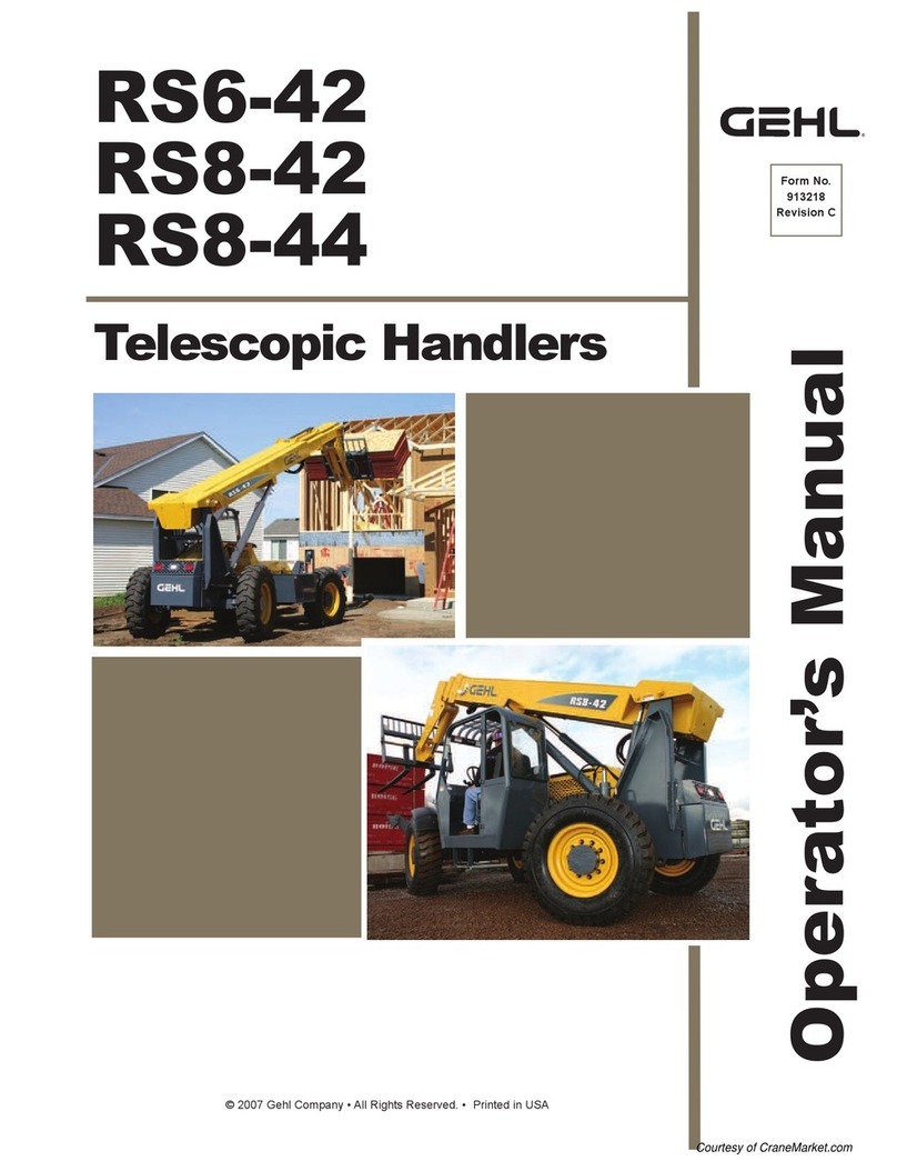
Gehl RS5-19 User manual

Operator’s Manual
RS5-19
Telescopic Handler
Beginning with Serial Number 50951
Form No.
50960066
Revision A
August
2013
®

Engine Failure
Indicator and Control Symbols
Read Operator’s
Manual
Turn Signals
Parking Brake
Safety Alert
Symbol
Fuel
Lights
Volume Half FullVolume Full
Engine Oil
Pressure
Hazard Flasher
Battery
Work Lights
Transmission
Temperature
Fan
Crab Steer
Lower Load
2-Wheel Steer
Raise Load
4-Wheel Steer
Engine Coolant
Temperature
Hourmeter
Retract Load
Volume Empty
Engine Electrical
Preheat
Tilt Rearward
Wiper/Washer
Extend LoadTilt Forward
Hydraulic Oil
Engine Start HornIgnition Off Ignition ON
Brake Failure
Diesel Fuel
Fasten Seat Belt
Tie Down PointLift Point Male Auxiliary
Hydraulic Coupler
Female Auxiliary
Hydraulic Coupler
Hydraulic Filter
Restriction
Engine Air Filter
Restiction
Axle OilEngine Oil
Neutral
Brake Fluid
Slow
Grease
Forward
Beacon
Rear Axle
Alignment
Front Axle
Alignment
Control Lever
Multi-Function
Audible Alarm
OFF
Reverse

PRINTED IN U.S.A. 150960066/AP0813
Table of Contents
Chapter Description Page
International Symbols . . . . . . . . . . . . . . . . . . . . . . . . . . . .Inside Front Cover
1Introduction . . . . . . . . . . . . . . . . . . . . . . . . . . . . . . . . . . . . . . . . . . . . . . . . . .2
2Specifications . . . . . . . . . . . . . . . . . . . . . . . . . . . . . . . . . . . . . . . . . . . . . . . . .4
3Checklists . . . . . . . . . . . . . . . . . . . . . . . . . . . . . . . . . . . . . . . . . . . . . . . . . .5, 7
4SAFETY . . . . . . . . . . . . . . . . . . . . . . . . . . . . . . . . . . . . . . . . . . . . . . . . . . . .8
5Indicators and Controls . . . . . . . . . . . . . . . . . . . . . . . . . . . . . . . . . . . . . . . .17
6Operation and Adjustments . . . . . . . . . . . . . . . . . . . . . . . . . . . . . . . . . . . . .28
7Lubrication . . . . . . . . . . . . . . . . . . . . . . . . . . . . . . . . . . . . . . . . . . . . . . . . . .43
8Service and Storage . . . . . . . . . . . . . . . . . . . . . . . . . . . . . . . . . . . . . . . . . . .46
9Decals . . . . . . . . . . . . . . . . . . . . . . . . . . . . . . . . . . . . . . . . . . . . . . . . . . . . . .61
10 Maintenance . . . . . . . . . . . . . . . . . . . . . . . . . . . . . . . . . . . . . . . . . . . . . . . . .65
Engine Diagnostic Codes (EDC’s) . . . . . . . . . . . . . . . . . . . . . . . . . . . . . . . .69
Electrical Schematics . . . . . . . . . . . . . . . . . . . . . . . . . . . . . . . . . . . . . . . . . .71
Hydraulic Schematics . . . . . . . . . . . . . . . . . . . . . . . . . . . . . . . . . . . . . . . . . .72
Load Zone Charts . . . . . . . . . . . . . . . . . . . . . . . . . . . . . . . . . . . . . . . . . . . . .73
Standard Hardware Torque Data . . . . . . . . . . . . . . . . . . . . . . . . . . . . . . . . .75
Index . . . . . . . . . . . . . . . . . . . . . . . . . . . . . . . . . . . . . . . . . . . . . . . . . . . . . . .76
Warranty . . . . . . . . . . . . . . . . . . . . . . . . . . . . . . . . . . . . . . .Inside Back Cover
IDENTIFICATION INFORMATION
Write the Gehl Telescopic Handler serial number below.
Refer to the model and serial number when inquiring about parts or service from your Gehl dealer.
The model and serial numbers for this machine are on a decal located inside the operator’s station.
MODEL NO. RS5-19
SERIAL NO.

50960066/AP0813 2PRINTED IN U.S.A.
The information in this Operator’s Manual was written to give the owner/operator assistance in preparing, adjust-
ing, maintaining and servicing of the Telescopic Handler. More important, this manual provides an operating plan
for safe and proper use of the machine. Major points of safe operation are detailed in the SAFETY chapter of this
manual.
GEHL Company asks that you read and understand the contents of this manual
COMPLETELY and become familiar with the machine before operating it.
The use of this Telescopic Handler is subject to certain hazards that cannot be eliminated by mechanical means,
but only by the exercise of intelligence, care and common sense. It is therefore essential to have competent and
careful operators, who are not physically or mentally impaired, and who are thoroughly trained in the safe opera-
tion of the equipment and the handling of the loads.
Throughout this manual information is provided that is set in italic type and introduced by the word IMPORTANT
or NOTE. Be sure to read carefully and comply with the message or directive given. Following this information
will improve operating and maintenance efficiency, help to avoid breakdowns and damage, and extend the
machine’s life. A chart of standard hardware torques is located in the back of this manual.
A storage pocket in the back of the seat is provided for storing the Operator’s Manual. After using the manual,
please return it to the pocket and keep it with the unit at all times! If this machine is resold, GEHL Company rec-
ommends that this manual be given to the new owner.
If this machine was purchased “used,” or if the owner’s address has changed, please provide your GEHL dealer or
GEHL Company Service Department with the owner’s name and current address, along with the machine model
and serial number. This will allow the registered owner information to be updated, so that the owner can be noti-
fied directly in case of an important product issue, such as a safety update program.
“Right” and “left” are determined from a position sitting on the seat and facing forward.
The wide GEHL dealership network stands ready to provide any assistance required, including providing genuine
GEHL service parts. All parts should be obtained from or ordered through your GEHL dealer. Give complete infor-
mation about the part, and include the model and serial number of the machine. Record the serial number in the
space provided on the previous page, as a handy record for quick reference.
GEHL Company reserves the right to make changes or improvements in the design or construction of any part
without incurring the obligation to install such changes on any unit previously delivered.
Chapter 1
INTRODUCTION
GEHL Company, in cooperation with the Society of Automotive
Engineers, has adopted this
Safety Alert Symbol
to identify potential safety hazards that if not properly avoided, could
result in injury. When you see this symbol in this manual or on the
machine itself, you are reminded to BE ALERT! Your personal safety is
involved!

PRINTED IN U.S.A. 350960066/AP0813
Identification
Telescopic Boom
Operator’s Station
Quick-attach
System
Tilt Cylinder Slave Cylinder
Dash Indicators
and Controls
Seat
Fuel Tank
Behind Access
Cover
Rear Boom
Access Cover
Lift Cylinder
Hydraulic Tank
Filler under
Engine Cover
Extend Cylinder
Inside Boom
Air Cleaner
under Engine
Cover
Exhaust Pipe
Auxilluary
Hydraulics
Rear View
Mirror

50960066/AP0813 4PRINTED IN U.S.A.
Chapter 2
SPECIFICATIONS
Lifting Performance
Maximum lift capacity:
5500 lbs. (2495 kg)
Maximum lift height:
19’ 1”(5.8 m)
Capacity at maximum lift height:
3000 lbs. (1361 kg)
Max. forward reach to load center:
11’ (3.35 m)
Capacity at maximum forward reach:
1850 lbs. (840 kg)
Maximum below grade reach:
0” (0 mm)
General Dimensions
Based on standard machine equipped
with listed tires, 48” masonry carriage
and 48” pallet forks.
Recommended tire type:
12 - 16.5 NHS 10-ply
Overall length, less forks:
148” (3.76 m)
Overall width:
71” (1.80 m)
Overall height:
76” (1.93 m)
Ground clearance: 10.5” (266 mm)
Wheelbase: 90” (2.29 m)
Outside turn radius: 132” (3.35 m)
Machine weight without attachment:
9,760 lbs. (4400 kg)
Instrumentation
Gauges: Fuel level, hourmeter,
coolant temperature, Voltmeter, Engine
speed
Monitoring lights:
Engine oil pressure, alternator,
hydrostatic drive oil temperature,
engine coolant temperature, air cleaner,
low fuel, hydraulic filter, engine failure
and glow indicator.
Visual indicators:
Boom angle, frame angle
Steering System
Steer Valve: Fixed-displacement rotary
Displacement/Rev: 7.3 cu. in. (120 cc)
System pressure: 2400 psi (165 bar)
Steer cylinders: 1 per axle
Steer mode valve:
3-position, 4-way solenoid with
dash-mounted switch actuation
Steer modes: 2-wheel, 4-wheel, crab
Braking System
Service brakes: Oil-immersed inboard
hydraulic wet-disc type; front axle
Manual foot pedal actuation
Parking brake: Spring-applied, hydraulic-
release disc-type in front axle
Actuation is electric switch with engine
running, automatic with engine off.
Electrical System
Type: 12-volt, negative ground
Battery: 950 minimum cold cranking
amps
Circuit protection: Fuse panel
Backup alarm: 107 dB(A)
Horn: 111 dB(A)
Alternator: 95 amp
Service Capacities
Cooling System: 12 qts. (11.3 L)
50/50 mixture
Anti-freeze protection: -31oF (-35oC)
Pressure cap: 14 psi (1.0 bar)
Fuel tank: 17 gals. (64 L)
Hydraulic tank:
18 gals. (68 L)
Axles:
Differentials: 4 qts. (3.8 L) ea.
Planetaries:
Front: 27 oz. (0.8 L) ea.
Rear: 30 oz. (0.9 L) ea.
Transfer Case (front axle only):
8 oz. (0.23 liters)
Hydrostatic Transmission
Type: Rexroth A4VG56DA/32
Speeds: 2 fwd / 2 rev
Travel Speeds:
Low speed: fwd/rev 4 mph (6.4
km/h)
High speed: fwd/rev 15 mph (24
km/h)
Axles (front and rear)
Front Axle: Dana model 60-211-69
Drive/steer, limited-slip differential,
full-time four-wheel drive
Rear Axle: Dana model 221-83
Drive/steer, open differential,
full-time four-wheel drive
Engine
Natural Aspiration Yanmar 4TNV98
202 cu. in. (3.32 liters) displacement
69.3 hp (50.7 kW) @ 2500 rpm
173 ft.-lbs. (235 Nm)
torque @ 1625 rpm
Oil capacity: 9.5 qts. (9.0 L)
Features:
In-line 4-cycle, 4-cylinder, direct-
injection diesel fuel system, in-line
5 micron fuel pre-filter with water
trap, and in-line 1 micron primary
fuel filter, positive pressure lubrica-
tion, liquid pressurized cooling
system, 19” (483 mm) suction fan,
dry dual-element air cleaner,
spin-on oil filter.
Hydraulic System
Type: Open-center
Pump: Single-section gear type
Displacement / revolution:
2.20 cu. in. (36 cc)
Flow @ 2530 RPM:
22 gpm (83 L/min)
Main relief pressure:
3350 psi (231 bar)
Steer relief pressure:
2400 psi (166 bar)
Hydraulic filter:
Return type, 16-micron
media, replaceable element.
Rated flow: 35 gpm (132 L/min)
Rated pressure: 1000 psi (70 bar)
By-pass pressure (full flow):
50 psi (345 kPa)

PRINTED IN U.S.A. 550960066/AP0813
Chapter 3
CHECKLISTS
PRE-DELIVERY
The following Checklist is an important reminder of inspec-
tions that MUST be made before delivering the Telescopic
Handler to the customer. Check off each item after the pre-
scribed action is taken.
√Check that:
q
NO parts of machine have been damaged in shipment.
Check for such things as dents and loose or missing parts;
correct or replace components as required.
q
Battery is securely mounted and not cracked. Cable con-
nections are tight. Electrolyte at proper level.
q
Cylinders, hoses and fittings are not damaged, leaking or
loosely secured.
q
Oil, fuel and air filters are not damaged, leaking or loosely
secured.
q
All grease fittings have been properly lubricated and no fit-
tings are missing; see Lubrication chapter of this manual.
q
Wheel nuts are torqued to 450 ft.-lbs. (610 Nm).
q
Tires are inflated to 65 psi (448 kPa) cold.
q
Hydraulic system reservoir, engine crankcase, engine
coolant, transmission and axles are filled to the proper
operating fluid levels.
q
All adjustments have been made to comply with the set-
tings given in this manual and in the separate engine man-
ual.
q
All guards, shields and decals are in place and securely
attached.
q
Model and serial numbers for this unit are recorded in
space provided on this page and page 1.
√Check that:
q
All indicators (lamps, switches, etc.) function properly.
q
All hand and foot controls operate properly.
q
Boom, Quick-attach System with attachment tool all func-
tion properly.
q
No hydraulic system leaks when under pressure.
q
Listen for abnormal noises or vibrations; if detected, deter-
mine their cause and repair as necessary.
I acknowledge that the pre-delivery procedures were per-
formed on this unit as outlined above.
Dealership’s Name
Dealer Representative’s Name
Date Checklist Filled Out
Machine Model # Machine Serial # Engine Serial #
DELIVERY
√Check that:
The following Checklist is an important reminder of valu-
able information that MUST be passed on to the customer at
the time the unit is delivered. Check off each item as you
explain it to the customer.
q
Review with the customer the contents of this manual and
the AEM Safety Manual and for the following:
q
The Index at the back, for quickly locating topics;
q
The Safety, Indicators and Controls, and Operation and
Adjustments chapters for information regarding safe use of
the machine.
q
The Lubrication, Service and Storage, and Maintenance
chapters for information regarding proper maintenance of
the machine. Explain that regular lubrication and mainte-
nance are required for continued safe operation and long
life.
q
Give this Operator’s Manual and the AEM Safety Manual
to the customer and instruct them to be sure to read and
completely understand their contents BEFORE operating
the unit.
q
Remind the customer of U.S. OSHA regulation 1910.178
(l), which specifies operator training requirements.
q
Explain that the customer must consult the engine manual
(provided) for related specifications, operating adjustments
and maintenance instructions.
q
Completely fill out the Owner’s Registration, including
customer’s signature, and return it to the Company.
Customer’s Signature
Date Delivered
Start the machine and test-run the unit while
checking that proper operation is exhibited by all
controls.
(Dealer’s File Copy - Remove at Perforation)

50960066/AP0813 6PRINTED IN U.S.A.
INTENTIONALLY BLANK
(To be removed as Dealer’s file copy)

PRINTED IN U.S.A. 750960066/AP0813
Chapter 3
CHECKLISTS
PRE-DELIVERY
The following Checklist is an important reminder of inspec-
tions that MUST be made before delivering the Telescopic
Handler to the customer. Check off each item after the pre-
scribed action is taken.
√Check that:
q
NO parts of machine have been damaged in shipment.
Check for such things as dents and loose or missing parts;
correct or replace components as required.
q
Battery is securely mounted and not cracked. Cable con-
nections are tight. Electrolyte at proper level.
q
Cylinders, hoses and fittings are not damaged, leaking or
loosely secured.
q
Oil, fuel and air filters are not damaged, leaking or loosely
secured.
q
All grease fittings have been properly lubricated and no fit-
tings are missing; see Lubrication chapter of this manual.
q
Wheel nuts are torqued to 450 ft.-lbs. (610 Nm).
q
Tires are inflated to 65 psi (448 kPa) cold.
q
Hydraulic system reservoir, engine crankcase, engine
coolant, transmission and axles are filled to the proper
operating fluid levels.
q
All adjustments have been made to comply with the set-
tings given in this manual and in the separate engine man-
ual.
q
All guards, shields and decals are in place and securely
attached.
q
Model and serial numbers for this unit are recorded in
space provided on this page and page 1.
√Check that:
q
All indicators (lamps, switches, etc.) function properly.
q
All hand and foot controls operate properly.
q
Boom, Quick-attach System with attachment tool all func-
tion properly.
q
No hydraulic system leaks when under pressure.
q
Listen for abnormal noises or vibrations; if detected, deter-
mine their cause and repair as necessary.
I acknowledge that the pre-delivery procedures were per-
formed on this unit as outlined above.
Dealership’s Name
Dealer Representative’s Name
Date Checklist Filled Out
Machine Model # Machine Serial # Engine Serial #
DELIVERY
√Check that:
The following Checklist is an important reminder of valu-
able information that MUST be passed on to the customer at
the time the unit is delivered. Check off each item as you
explain it to the customer.
q
Review with the customer the contents of this manual and
the AEM Safety Manual and for the following:
q
The Index at the back, for quickly locating topics;
q
The Safety, Indicators and Controls, and Operation and
Adjustments chapters for information regarding safe use of
the machine.
q
The Lubrication, Service and Storage, and Maintenance
chapters for information regarding proper maintenance of
the machine. Explain that regular lubrication and mainte-
nance are required for continued safe operation and long
life.
q
Give this Operator’s Manual and the AEM Safety Manual
to the customer and instruct them to be sure to read and
completely understand their contents BEFORE operating
the unit.
q
Remind the customer of U.S. OSHA regulation 1910.178
(l), which specifies operator training requirements.
q
Explain that the customer must consult the engine manual
(provided) for related specifications, operating adjustments
and maintenance instructions.
q
Completely fill out the Owner’s Registration, including
customer’s signature, and return it to the Company.
Customer’s Signature
Date Delivered
Start the machine and test-run the unit while
checking that proper operation is exhibited by all
controls.
(Pages 5 and 6 have been removed at perforation)

50960066/AP0813 8PRINTED IN U.S.A.
Chapter 4
SAFETY
DANGER
“DANGER” indicates an imminently haz-
ardous situation that, if not avoided, will result
in death or serious injury.
WARNING
“WARNING” indicates a potentially hazardous
situation that, if not avoided, could result in
death or serious injury.
CAUTION
“CAUTION” indicates a potentially hazardous
situation that, if not avoided, may result in
minor or moderate injury. It may also alert to
unsafe practices.
Gehl Company ALWAYS takes the operator’s safety
into consideration when designing its machinery, and
guards exposed moving parts for his/her protection.
However, some areas cannot be guarded in order to
assure proper operation. Further, this Operator’s
Manual and decals on the machine warn of additional
hazards and should be read and observed closely.
REMEMBER! It is the owner’s responsibility for com-
municating information on the safe use and proper
maintenance of this machine! This includes providing
understandable interpretations of these instructions
for operators who are not fluent in reading English.
It is the responsibility of the operator to read and
understand the Operator’s Manual and other informa-
tion provided and use the correct operating procedure.
Machines should be operated only by qualified opera-
tors.
MANDATORY SAFETY SHUTDOWN
PROCEDURE
BEFORE cleaning, adjusting, lubricating or ser-
vicing the unit:
1. Stop machine on a level surface. (AVOID park-
ing on a slope, but if necessary, park across the
slope and block the tires.)
2. Fully retract the boom and lower the attach-
ment tool to the ground. Idle engine for gradual
cooling.
3. Place controls in neutral and apply parking
brake.
4. Shut off the engine and remove the key.
ONLY when you have taken these precautions can
you be sure it is safe to proceed. Failure to follow
the above procedure could lead to death or serious
bodily injury.
The above Safety Alert Symbol means ATTENTION!
ALWAYS BE ALERT! YOUR SAFETY IS
INVOLVED! It stresses an attitude of safety aware-
ness and can be found throughout this Operator’s
Manual and on the machine itself.
Before attempting to operate this
equipment, read and study the following
safety information. In addition, be sure that
everyone who operates or works with this
equipment, whether family member or
employee, is familiar with these
safety precautions.

PRINTED IN U.S.A. 950960066/AP0813
SAFETY
Additional Safety Reminders
ÜUser/operator safety practices, as established by
industry standards, are included in this Operator’s
Manual and intended to promote safe operation of
the machine. These guidelines do not preclude the
use of good judgment, care and common sense as
may be indicated by the particular jobsite work
conditions.
ÜIt is essential that operators be physically and men-
tally fit, free of mind-altering drugs and chemicals,
and thoroughly trained in the safe operation of the
machine. Such training should be presented com-
pletely to all new operators and not condensed for
those claiming previous experience. Information
on operator training is available from several
sources, including the manufacturer.
ÜSome illustrations used in this manual may show
doors, guards and shields open or removed for
illustration purposes ONLY. BE SURE that all
doors, guards and shields are in their proper oper-
ating positions before starting the engine.
Before Operation Safety Reminders
ÜCheck brakes, steering, and hydraulic system prior
to starting operation. Operate all controls to ensure
proper operation. Observe all gauges and indica-
tors for proper operation. If any malfunctions are
found, correct the cause prior to using the machine.
ÜALWAYS wear appropriate personal protective
equipment for the job and working conditions.
Hard hats, goggles, protective shoes, gloves,
reflector-type vests, respirators and ear protection
are exampes of types of equipment that may be
required. DO NOT wear loose fitting clothing,
long hair, jewelry or loose personal items while
operating or servicing the machine.
ÜALWAYS check the job site for terrain hazards,
obstructions and people. Remove all objects that
do not belong in or on the machine and its equip-
ment.
WARNING
U.S. OSHA regulations require employers in
general industry and the construction, ship-
yard and cargo-handling industries (excepting
agricultural operations) to ensure that forklift
operators are competent, as demonstrated by
successful completion of a training course.
The training course must consist of a combi-
nation of formal instruction and practical
training, including both forklift-related and
workplace-related topics, and evaluation of
the operator’s performance in the workplace.
All operator training and evaluation is to be
conducted by persons who have the know-
ledge, training and experience to train and
evaluate operators.
WARNING
ALWAYS maintain a safe distance from elec-
tric power lines and avoid contact with any
electrically charged conductor or gas line. It is
not necessary to make direct contact with a
power line for power to ground through the
structure of the machine. Keep the boom at
least 10 ft. (3 m) from all power lines.
Accidental contact or rupture can result in
electrocution or an explosion. Contact the
North American One-Call Referral System at
(888) 258-0808 for the local “Digger’s Hotline”
number or proper local authorities for utility
line locations before starting to dig!

50960066/AP0813 10 PRINTED IN U.S.A.
ÜWalk around the machine and warn all personnel
who may be servicing the machine or who are in
the machine path prior to starting. DO NOT start
until all personnel are clearly away from the
machine.
Operation Safety Reminders
ÜAny or all of the following elements may affect the
stability of the machine: terrain, engine speed, type
of load being carried and placed, improper tire
inflation, weight of the attachment tool, and abrupt
movement of any control lever. IF YOU ARE
NOT CAREFUL WHILE OPERATING THIS
MACHINE, ANY OF THE ABOVE FACTORS
COULD CAUSE THE MACHINE TO TIP
AND THROW YOU OUT OF THE OPERA-
TOR’S STATION, WHICH MAY CAUSE
SERIOUS BODILY INJURY OR DEATH!
ÜALWAYS wear the seat belt provided to prevent
being thrown from the machine. If you are in an
overturn:
- DO NOT jump!
- Hold on tight and stay with the machine!
- Lean away from the fall!
ÜALWAYS keep hands, feet and arms inside of the
operator’s station when operating the machine!
ÜDO NOT depend on the backup alarm to clear
bystanders out of the path of the machine. Always
look in the direction of travel. Look to the rear
before backing.
ÜALWAYS use the recommended hand holds and
steps with at least three points of support when get-
ting on and off the machine. Keep steps and plat-
form clean. Face the machine when climbing up
and down.
ÜDO NOT raise or drop a loaded fork or bucket sud-
denly. Abrupt movements under load can cause
serious instability.
ÜStudy the load chart carefully. It shows maximum
capacity to be lifted and placed at specific outward
and upward distances. ALWAYS be aware of load
weights prior to attempting lift and placement with
this machine.
ÜDO NOT exceed the machine’s rated operating
capacity for the type of attachment tool being used.
ÜDO NOT allow minors or any unqualified person-
nel to operate or be near the machine unless prop-
erly supervised.
ÜDO NOT start the engine or operate any controls
unless properly seated in the operator’s seat!
ÜDO NOT run the engine in an enclosed area with-
out providing proper ventilation for the exhaust.
Exhaust gases contain carbon monoxide, an odor-
less and deadly gas. Internal combustion engines
deplete the oxygen supply within enclosed spaces
and may create a serious hazard unless the oxygen
is replaced. This includes the atmosphere within
the cab when equipped.
ÜDO NOT leave the operator’s station with the
boom and attachment tool raised. ALWAYS lower
the boom and attachment tool to the ground, shut
off the engine and engage the parking brake
BEFORE leaving the operator’s station.
ÜNEVER travel with the boom above the carry
position (attachment tool should be at minimum
ground clearance.) Boom should be fully retract-
ed.
ÜDO NOT drive too close to an excavation or ditch.
BE SURE that the surrounding ground has ade-
quate strength to support the weight of the machine
and the load it is carrying.
ÜDO NOT turn quickly while traveling on a slope or
operate the machine beyond the grade and slope
limits noted in the Operation and Adjustments
chapter of the Operator’s Manual.
ÜNEVER allow any riders on this machine or use as
a lift for personnel. This is strictly a single-seat,
NO passenger machine!
ÜWhen road travel is required, know and use the
signaling devices on the machine. Provide an
escort and Slow-Moving Vehicle (SMV) emblem
when required.
ÜIf necessary to park on a slope, park across the
slope and block the tires.
SAFETY

PRINTED IN U.S.A. 11 50960066/AP0813
Suspended Load Safety Reminders
The handling of suspended loads by means of a truss
boom, winch, boom mounted lift hook or other similar
device can introduce dynamic forces affecting the sta-
bility of the machine that are not considered in the sta-
bility criteria of industry test standards. Grades and
sudden starts, stops and turns can cause the load to
swing and create a hazard. Refer to the following
guidelines for handling suspended loads.
ÜDO NOT exceed the rated capacity of the tele-
scopic handler as equipped for handling suspend-
ed loads. The weight of the rigging must be
included as part of the load.
ÜDuring transport, the length of the rigging
between the attachment and load should be as
short as possible to reduce booms height and
movement. DO NOT raise the load more than 12
inches (305 mm) above the ground, or raise the
boom more than 45 degrees.
ÜOnly lift the load vertically – NEVER drag it hor-
izontally.
SAFETY
WARNING
U.S. OSHA regulations effective November 8,
2010 (29 CFR Part 1926, Subpart CC - Cranes
and Derricks in Construction) include require-
ments for employers that use powered indus-
trial trucks ("forklifts") configured to hoist (by
means of a winch or hook) and move sus-
pended loads horizontally. In particular, this
regulation applies to any rough-terrain forklift
(e.g., "telescopic handler") equipped with a jib
or truss boom with a hook (with or without a
winch), or a hook assembly attached to the
forks. [Note: This regulation is in addition to
the OSHA regulation that requires specific
forklift operator training: §1910.178(l).]
When a forklift / telescopic handler is config-
ured and used for hoisting, the employer must
ensure that:
1. Forklift, lift equipment and rigging have
been inspected (each shift, month and
year) and are in good, safe condition and
properly installed.
2. An operator's manual and applicable load
charts are on the forklift.
3. Work zone ground conditions can support
the equipment and load. Any hazardous
conditions in the work area have been
identified, and the operator notified.
4. Equipment is being used within its rated
capacity and in accordance with the manu-
facturer's instructions.
5. Operator and crew members have been
trained in the safe use and operation of the
equipment, including how to avoid electro-
cution.
6. During use, no part of the equipment, load
line or load will be within the minimum
clearance distance specified by OSHA [10
feet (3.0 m), and more for lines rated over
50 kV] of any energized power line, and
any taglines used are non-conductive.
7. In addition, for lift equipment with a rated
capacity greater than 2000 lbs. (907 kg),
the employer must ensure that:
a.) An accessible fire extinguisher is on
the forklift;
b.) Monthly and annual inspections are
performed and documented, and
records retained (three months for
monthly, one year for annual);
c.) Before November 10, 2014, operators
must have had the additional training
and qualification / certification required
by OSHA regulations §1926.1427 and
§1926.1430.
Note: Refer to the full text of the OSHA crane
regulation (29 CFR Part 1926, Subpart CC) for
a detailed description of the regulatory
requirements.

50960066/AP0813 12 PRINTED IN U.S.A.
ÜUse multiple pickup points on the load when pos-
sible. Use taglines to restrain the load from
swinging and rotating.
ÜStart, travel, turn and stop SLOWLY to prevent
the load from swinging. DO NOT exceed walking
speed.
ÜInspect rigging before use. Rigging must be in
good condition and in the U.S. comply with
OSHA regulation §1910.184, “Slings,” or
§1926.251, “Rigging equipment for material han-
dling.”
ÜRigging equipment attached to the forks must be
secured such that it cannot move either sideways
or fore and aft. The load center must not exceed
24 inches (610 mm).
ÜDO NOT lift the load with anyone on the load,
rigging or lift equipment, and NEVER lift the
load over personnel.
ÜBeware of the wind, which can cause suspended
loads to swing, even with taglines.
ÜDO NOT attempt to use frame-leveling to com-
pensate for load swing.
Servicing Safety Reminders
ÜALWAYS be aware of and avoid pinch-point areas
on the machine, such as wheels-to-frame, cylin-
ders-to-frame, boom- and attachment-tool-to-
frame.
ÜNEVER attempt to by-pass the keyswitch to start
the engine. ONLY use the jump-starting procedure
detailed in the Service and Storage chapter.
ÜNEVER use your hands to search for hydraulic
fluid leaks. Instead use a piece of paper or card-
board. Escaping fluid under pressure can be invis-
ible and can penetrate the skin, causing serious
injury. If any fluid is injected into your skin, see a
doctor at once. Injected fluid MUST be surgically
removed by a doctor familiar with this type of
injury or gangrene may result.
ÜALWAYS wear safety glasses with side shields
when striking metal against metal. In addition, it is
also recommended that a softer (chip-resistant)
material be used to cushion the blow. Failure to
heed could lead to serious injury to the eyes or
other parts of the body.
ÜDO NOT refill the fuel tank when the engine is
hot. Allow engine to cool down before refilling to
prevent hot engine parts from igniting the fuel if it
should spill or splash.
ÜDO NOT smoke while filling the fuel tank, work-
ing on the fuel or hydraulic systems, or working
around the battery.
ÜDO NOT fill the fuel tank completely. Allow room
for expansion. Maintain control of the fuel filler
nozzle when filling the tank. Use the correct fuel
grade for the operating season.
ÜStatic electricity can produce dangerous sparks at
the fuel-filling nozzle. Do not wear polyester, or
polyester-blend clothing while fueling. Before
fueling, touch the metal surface of the machine
away from the fuel fill to dissipate any built-up sta-
tic electricity. Do not re-enter the machine but stay
near the fuel filling point during refueling to mini-
mize the build-up of static electricity. Do not use
cell phones while fueling. Make sure the static line
is connected from the machine to the fuel truck
before fueling begins.
ÜUltra-Low Sulfur Diesel (ULSD) poses a greater
static ignition hazard than earlier diesel formula-
tions. Avoid death or serious injury from fire or
explosion; consult with your fuel or fuel system
supplier to ensure the entire fuel delivery system is
in compliance with fueling standards for proper
grounding and bonding practices.
ÜNEVER use fuel for cleaning purposes.
ÜDO NOT remove the radiator cap after the engine
has reached operating temperature or if it is over-
heated. At operating temperatures, the engine
coolant will be extremely hot and under pressure.
ALWAYS wait for the engine to cool before
attempting to relieve pressure and remove the radi-
ator cap. Failure to heed this warning could result
in severe burns.
SAFETY

PRINTED IN U.S.A. 13 50960066/AP0813
SAFETY
ÜDO NOT loosen or disconnect any hydraulic lines,
hoses or fittings without first relieving hydraulic
circuit pressure. Also, be careful not to touch any
hydraulic components that have been in recent
operation because they can be extremely hot and
can burn you!
ÜAvoid lubrication or mechanical adjustments with
the machine in motion or the engine running. If the
engine must be running to make certain adjust-
ments, place the equipment in a safe position,
place the transmission in neutral, apply the parking
brake, securely block the wheels and use extreme
caution.
ÜTo ensure continued safe operation, replace dam-
aged or worn-out parts with genuine Gehl service
parts before using this equipment.
Modifications, Nameplates, Markings and
Capacities
ÜModifications and additions that affect capacity or
safe operation must never be performed without
the manufacturer’s prior written approval. Where
such authorization is granted, any applicable mark-
ings are to be changed accordingly.
ÜAll attachment tools MUST be marked to identify
the attachment tool and the total capacity with the
attachment tool at maximum elevation with the
load laterally centered.
ÜALWAYS be sure all nameplates, warnings and
instruction markings are in place and legible.
Local government regulations may require specif-
ic decals, which are the responsibility of the owner
to provide.
Safety Guards and Warning Devices
ÜThis machine is fitted with a Roll-Over Protective
Structure (ROPS) and Falling Object Protective
Structure (FOPS) in accordance with industry stan-
dards. The structure is intended to offer protection
to the operator in case of an overturn and from
falling objects, but it cannot protect against every
possible hazard. Therefore it should not be consid-
ered a substitute for good judgment and safe prac-
tices in operating the machine. If the ROPS / FOPS
structure is damaged, it must be replaced to restore
the protection it provides.
ÜThis machine is equipped with a horn and backup
alarm. The user must determine if operating condi-
tions require the machine to be equipped with
additional devices (mirrors, rotating beacon, etc.)
and be responsible for providing and maintaining
such devices.

50960066/AP0813 14 PRINTED IN U.S.A.
SAFETY
L65927 L65928
L65927
L65927
L66613
072798
L65933
L70305
L65942

PRINTED IN U.S.A. 15 50960066/AP0813
SAFETY
L65933
L65927
L70305
072798
RED
L66613
L65928
L65942

50960066/AP0813 16 PRINTED IN U.S.A.
L70307
L70306
101506
101506
L65926
L70306
L70307
L65926
L65932
L65928
100359
L65928
100359
L65932
SAFETY

PRINTED IN U.S.A. 17 50960066/AP0813
GUARDS AND SHIELDS
Whenever possible and without affecting machine
operation, guards and shields are used to protect poten-
tially hazardous areas. In many places, decals are also
provided to warn of potential hazards and to display
special operating procedures.
WARNING
Read and thoroughly understand all safety
decals on the Telescopic Handler before oper-
ating it. DO NOT operate the machine unless
all factory-installed guards and shields are
properly secured in place.
CAUTION
Before operating the Telescopic Handler,
become familiar with and know how to use
ALL safety devices and controls. Know how to
stop the machine operation before operating
it. This Gehl machine is designed and intend-
ed to be used ONLY with a Gehl Company
attachment tool, or a Gehl Company approved
accessory or referral attachment tool. Gehl
Company cannot be responsible for safety if
the machine is used with an unapproved
accessory or attachment tool.
Chapter 5
INDICATORS AND CONTROLS
Operator’s Compartment and Indicators/Controls Locations
Frame Angle
Indicator
Boom Control
Joystick
Key Switch
Start Button
Boom Angle
Indicator
Brake Pedal
Attachment / Auxiliary
Hydraulics Joystick
Arm Rest
Throttle Pedal
Steering Wheel Instrument and
Switch Panel
Horn Button
Travel Direction
Lever

50960066/AP0813 18 PRINTED IN U.S.A.
Load Zone Charts: A
set of flip charts show
lift height and reach lim-
its relative to the load
weight being handled
with various attachment
tools.
INSTRUMENT AND SWITCH PANEL
Located to the right of the steering wheel, this panel
contains the instrument gauges, indicator lamps and
function switches.
Instrumentation
A - Multi-Function Display Screen: This screen dis-
plays the following functions:
•fuel level at all times,
•engine coolant temperature,
•engine speed,
•voltmeter
•hourmeter
•250 hour maintenance reminder
•error fault codes
•DPF regeneration status and level
DASH PANEL AREA
A - Key switch OFF: When the key is vertical in the
keyswitch, power is disconnected from the battery to
the control and instrument panel electrical circuits.
Also, this is the only position in which the key can be
inserted or removed.
B - Key switch ON: When the key is turned one posi-
tion clockwise from the vertical (OFF) position, power
from the battery is supplied to all controls and multi-
function display panel electrical circuits. Indicators on
the multi-function display should light up momentari-
ly.
When the key is in this position, the engine pre-heat
indicator will stay on until the engine is pre-heated. In
colder temperatures the pre-heat indicator will stay lit
for 3-30 seconds. When the pre-heat indicator light
goes out the engine can be started.
C - Start Button: With keyswitch in ON position,
press the button to activate the starter. Release it as
soon as the engine starts.
NOTE: If the engine requires repeated attempts
to start, the key MUST be returned to the OFF
position between starting attempts to prevent bat-
tery run down.
IMPORTANT: Do not use additional starting aids
such as ether injection when using the electrical
engine preheat.
D - Horn Button: Press the horn button to activate
warning sound.
Instrument and Switch Panel
Key Switch, Start and Horn Buttons
A
D
C
B
A
E
D
C
F
G
J
I
H
K
B
Table of contents
Other Gehl Lifting System manuals
Popular Lifting System manuals by other brands

Modulift
Modulift MOD 24 User instructions

Rotary
Rotary SPOA7 Series Installation instruction

Chicago Electric
Chicago Electric 47591 Assemble and operating instructions

National Auto Tools
National Auto Tools NSS-8000 instructions

Beachcomber
Beachcomber AIRLIFT Assembly, Installation Instructions & Parts List

Lift-Rite
Lift-Rite SPRINT Owner and operational manual

Ranger Products
Ranger Products BendPak P-6 Installation and operation manual

Performance Tool
Performance Tool W41018 owner's manual

Hatchlift
Hatchlift RV Bedlift Kit instructions

Enerpac
Enerpac MLSF3 Operation and maintenance manual

VMB
VMB TL-063B Operating instructions & user manual

BIG
BIG Digital Radio Operation manual