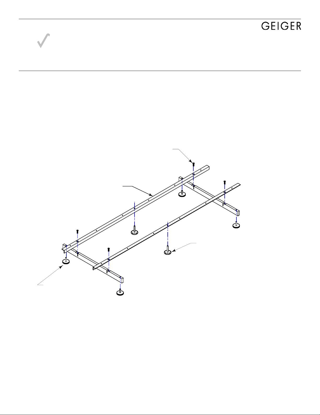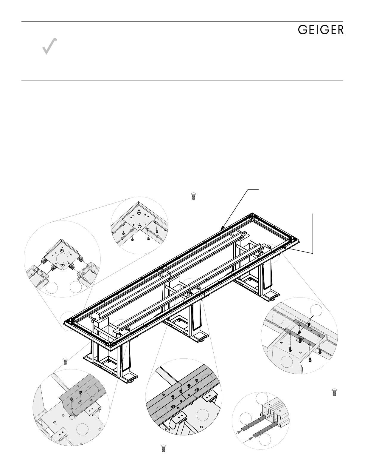
1. Install Structure
A. Locate plinth bases (#5) per installation drawing.
B. Connect Hat Channels (#44) to Plinth bases (#5). See Detail A.
C. Connect Corner Blocks (#49) to each end of short beams (#14).
See Detail B. Do this for both ends of table structure. Do not connect long beams yet.
D. !ATTENTION!: Before attaching beams to tops, insert two Beam Brackets (#15) for each plinth base
into slots of the Long Beams (#14) as shown in Detail C.
E. Center long beams (#14) over plinth base assembly.
F. Slide Beam brackets(#15) within beam channels so that the holes in these brackets align with the holes
on the plinth bases as shown in Detail D.
G. Fasten beams to bases. Screw up through bottom of holes in base arms into Beam Brackets (#15)
inserted in step D. Be sure to use outer set of holes on base arms.
H. Attach End Beam/Corner Block assembly completed in step C to ends of long beams.
I. Level structure end-to-end and side-to-side. Adjust base levelers as required.
44 5
44
44
5
Detail C
15
15
14
Detail B
49
14 14
14
5
15
4x SCREW-4
4x SCREW-4
Detail D
from underneath
Detail A
Center Bases
4x SCREW-4
Detail A
End Bases
2x SCREW-4
Insert beam Brackets into long beams
(see Detail C):
(4) if table has two bases
(6) if table has three bases
(8) if table has four bases
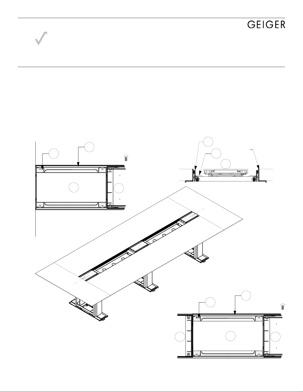
Caucus
Right ON SITE Installation Principles
ROS-APT Caucus Plinth Table with Trough 1B4FDL
Note: Details apply, however the actual configuration of your table may vary from what is depicted here.