Geiser One 1BS911 User manual


82-1/2" tile 60" tile
22-1/2" tile
30" tile
37-1/2" tile
45" tile
52-1/2" tile
30"
60"
78-1/2"
0"
22-1/2"
52-1/2"
78-1/2"
30"
60"
78-1/2"
22-1/2"
52-1/2"
63-7/16"
30" 30"
63-7/16"
22-1/2"
48-7/16" 48-7/16"
Right ON SITE Installation Principles

37-1/2" tile 30" tile
45" tile
52-1/2" tile
75" tile
30"
60"
71"
0"
22-1/2"
52-1/2"
71"
30"
60"
71"
22-1/2"
56"
30"
56"
Right ON SITE Installation Principles

30" tile 22-1/2" tile
45" tile
67-1/2" tile
30"
63-9/16"
0"
22-1/2"
52-1/2"
30"
22-1/2"
48-7/16"
30"
63-9/16"
37-1/2" tile
63-9/16"
48-7/16"
Right ON SITE Installation Principles

60" tile
37-1/2" tile 30" tile
52-1/2" tile
22-1/2" tile
30" tile
45" tile
22-1/2" tile 15" tile
30"
56"
0"
22-1/2"
56"
30"
56"
30"
48-7/16"
22-1/2"
48-7/16"
0"
30"
48-7/16"
30"
41"
22-1/2"
41"
0"
30"
41"
Right ON SITE Installation Principles


Page
6
6.
Connect
Optional
Task
Light
A.
Connect
the
LED
light
cord
that
exits
through
shelf
and
wall
panel
and
down
wall
to
the
power
supply.
Up
to
6
light
cords
and
a
total
of
16
feet
of
lighting
can
be
powered
by
1
power
supply.
The
power
supply
includes
a
dimmer
receiver
module
on
the
side
of
the
power
supply.
B.
If
2
or
3
power
supplies
are
required
,
interconnect
each
power
supply
to
the
adjacent
power
supply
with
the
provided
19"
connecting
cable.
C.
Plug
the
cord
of
the
last
power
supply
in
to
a
power
outlet.
D.
Program
the
dimmer
remote
control
to
operate
the
power
supply
or
supplies
using
the
instructions
below.
E.
Attach
the
remote
control
holder
to
furniture
with
provided
double
stick
tape
or
screw.
7.
Programming
Remote
Control
A.
Briefly
press
the
button
of
the
power
supply.
The
indicator
LED
is
lit
blue.
B.
Keep
the
1-channel
remote
control
within
reach.
Remove
any
protective
foil.
C.
Remove
and
reinsert
remote
battery.
Press
the
ON/OFF
button
on
the
remote
for
at
least
5
seconds.
If
the
programming
is
successful,
the
LED
on
the
power
supply
goes
out.
dimmer
receiver
module
plug
connecting
cable
here
plug
light
cords
here
dimmer
receiver
module
connecting
cable
Installation
Principles
Geiger One
Right
ON
SITE
1BS911
Note:
Details
apply,
however
the
actual
configuration
of
your
product
may
vary
from
what
is
depicted
here.

7.
Programming
Remote
Control
(continued)
D.
To
program
multiple
power
supplies
to
work
with
a
single
remote,
briefly
press
the
button
of
all
power
supplies
that
you
want
to
program.
The
indicator
LEDs
will
be
lit
blue.
E.
Keep
the
1-channel
remote
control
within
reach.
Remove
any
protective
foil.
F.
Remove
and
reinsert
the
remote
battery.
Press
the
ON/OFF
button
for
at
least
5
seconds.
If
the
programming
is
successful,
the
LEDs
on
the
power
supplies
will
go
out.
8.
Operating
Remote
Control
A.
Switching
the
lights
ON/OFF
Press
button
ON/OFF
to
switch
on
all
luminaires
of
lighting
group
1.
Press
the
button
once
more
to
switch
off
the
lighting
group.
B.
Setting
the
color
temperature
Turn
the
color
wheel
to
set
the
color
temperature
in
the
warm
to
cold
white
range.
C.
Setting
the
brightness
The
brightness
can
be
set
gradually
or
continuously.
D.
Gradual
Setting
(100
%
-
75
%
-
50
%
-
25
%
-
0
%)
Press
the
left
arrow
button
to
reduce
the
brightness
gradually.
Press
the
right
arrow
button
to
increase
the
brightness
gradually.
E.
Continuous
Setting
Keep
the
left
arrow
button
pressed
to
reduce
the
brightness
continuously.
Keep
the
right
arrow
button
pressed
to
increase
the
brightness
continuously.
Page
7
Installation
Principles
Geiger One
Right
ON
SITE
1BC911
Note:
Details
apply,
however
the
actual
configuration
of
your
product
may
vary
from
what
is
depicted
here.

Attach Fixed HeightorAdjustable HeightLegsto Utility Cabinet
Page8
(4x)1BPJG T
5/16"x5/8"
6mm hex head
-Attach RearLeg Clam p to case
-Slide leg through hole to leg bracket.
-Attach leg to bottom bracket
-Attach FrontLeg Clam p,HandTighten ing
Note: Makesu re leg pow er co rd faces out
fro m wall
Attach rea r leg clam p 1BPJH J to utility top panel
using (4x)#8 x 3/4" pan head woodscrew s
(2x)1BPJH J
leg clam p
(2x)1BPJH L
5/16-18
elevator bolt
(2x)1BG C V B
5/16-18 flange nut
(Finger Tighten Only)
Note: Rem ovethis sh ipping boltfro m the
bottom ofthe legs prior to a ssem b ly.
Geiger One
RightON SITE Installation Principles
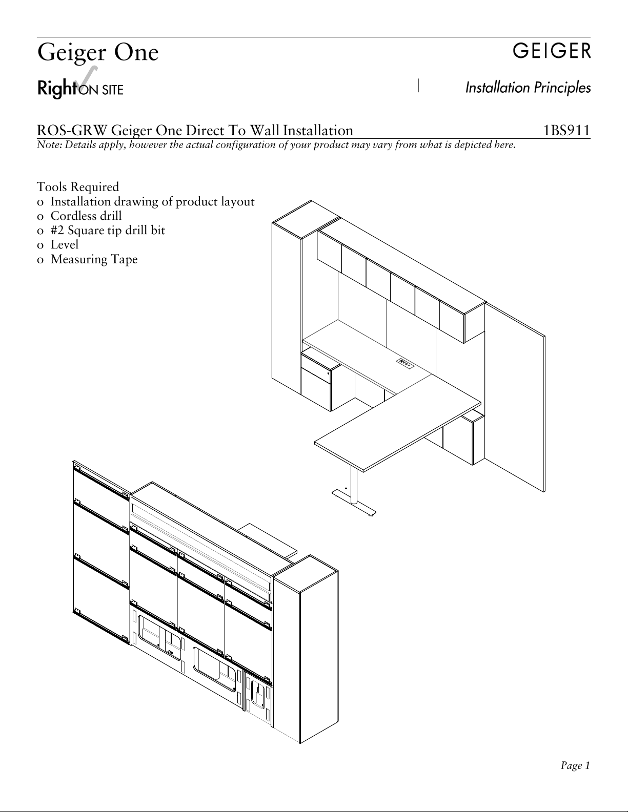
RO S-GRW Geiger OneDirect To WallInstallation 1BS911
Note: Details apply,how ever the actualco n figuration ofyourproductmayvary fro m whatis depicted here.

Right ON SITE Installation Principles


Right ON SITE Installation Principles

1-1/2" gap
B
C
D
E
AC
C
F
F(2x) cable manager
Optional 1EPS-P PlugStrip
Run cable through Optional Shroud
E
DControl Box Power Cord - 1BPNS4
Connects control box to power source
Can plug into wall or plug strip
(3x) Extension Cord - 1BPNS6
Connects leg cables to control box
C
Handset - 1BPNS8
Align with front edge just inside
bracket. Connects to control box port
B
3-Leg control box - 1BM65H
A
Connect Beams & brackets to worksurfaces using #8 x 1" pan head
wood screws (part 51153).
(2x) flat plates (10188)
To connect power to the height adjustable legs:
1. Attach an extension cord to each leg.
2. Connect the other end of the extension cord to the
control box.
3. Connect the hand set to the control box.
4. Plug the power cord into the control box and then to
an outlet.
You should hear a double click and see a flashing “0”. If
you see 4 dash lines then unplug the power cord and
wait 10 seconds before plugging back in. Press and hold
the down button and the desk will start to move up.
Keep the down bottom pressed and wait until the
display reads about 40” and you hear another double
click. You can now use the up and down bottom to reach
your desired height. Note that if you lose building power
you will have to go through these step again to reset
your desk.
Right ON SITE Installation Principles

1-1/2" gap
B
D
E
C
A
C
F
Optional 1EPS-P PlugStrip
Run cable through Optional Shroud
E
DControl Box Power Cord - 1BPNS5
Connects control box to power source
Can plug into wall or plug strip
(2x) Extension Cord - 1BPNS6
Connects leg cables to control box
C
Handset - 1BPNS8
Align with front edge just inside
bracket. Connects to control box port
B
2-Leg conrol box - 1BM65G
A
Connect Beams & brackets to worksurfaces using #8 x 1" pan head
wood screws (part 51153).
F(2x) cable manager
To connect power to the height adjustable legs:
1. Attach an extension cord to each leg.
2. Connect the other end of the extension cord to the
control box.
3. Connect the hand set to the control box.
4. Plug the power cord into the control box and then to
an outlet.
You should hear a double click and see a flashing “0”. If
you see 4 dash lines then unplug the power cord and
wait 10 seconds before plugging back in. Press and hold
the down button and the desk will start to move up.
Keep the down bottom pressed and wait until the
display reads about 40” and you hear another double
click. You can now use the up and down bottom to reach
your desired height. Note that if you lose building power
you will have to go through these step again to reset
your desk.
Right ON SITE Installation Principles

Optional 1EPS-P PlugStrip
Run cable through Optional Shroud
E
DControl Box Power Cord - 1BPNS5
Connects control box to power source
Can plug into wall or plug strip
(2x) Extension Cord - 1BPNS6
Connects leg cables to control box
C
Handset - 1BPNS8
Align with front edge just inside
bracket. Connects to control box port
B
2-Leg conrol box - 1BM65G
A
Connect Beams & brackets to worksurfaces using #8 x 1" pan head
wood screws (part 51153).
B
C
D
E
A
To connect power to the height adjustable legs:
1. Attach an extension cord to each leg.
2. Connect the other end of the extension cord to the
control box.
3. Connect the hand set to the control box.
4. Plug the power cord into the control box and then to
an outlet.
You should hear a double click and see a flashing “0”. If
you see 4 dash lines then unplug the power cord and
wait 10 seconds before plugging back in. Press and hold
the down button and the desk will start to move up.
Keep the down bottom pressed and wait until the
display reads about 40” and you hear another double
click. You can now use the up and down bottom to reach
your desired height. Note that if you lose building power
you will have to go through these step again to reset
your desk.
Right ON SITE Installation Principles