GEM AD500 User manual

AD500
Instruction Manual
Automatic Door Operator
For easy to follow installation instructions, please visit link
below for installation video or scan QR code on the right
http://www.gianni.com.tw/AutomaticDoorOperator_AD500.html

Table of Contents
1. General Safety Precautions -------------------------------------------
2. Declaration by Manufacturer -----------------------------------------
3. Product Features -------------------------------------------------------
4. Parts Identification ------------------------------------------------------
5. Specifications -------------------------------------------------------------
6. Before Installation ------------------------------------------------------
7. Template Instructions ---------------------------------------------------
8. Installation Preparation by Frame Types ---------------------------
9. Base Plate & Reducer Installation ------------------------------------
10. Push Arm Assembly Installation (For Outswing Doors) --------
11. Sliding Arm Assembly Installation (For Inswing Doors) --------
12. Learning Mode ----------------------------------------------------------
13. Operation Controller ---------------------------------------------------
14. Optional Accessories --------------------------------------------------
15. Trouble Shooting & Maintenance------------------------------------
16. Notes for Engineers ----------------------------------------------------
17. Safety Instructions for Users -----------------------------------------
01
01
02
03
04
07
12
16
18
21
24
26
26
27
28
29
31

This instruction manual is intended solely for qualified professionals. All installations, electrical connections and
adjustments must follow the installation instructions.
Please read these instructions carefully and watch video instructions before installing this unit. Incorrect
installation may result in severe personal injury and/or damage to property.
Packaging materials (plastic and polystyrene, etc) should be discarded or recycled in accordance with waste
disposal regulations and should be kept out of reach of children.
Do not install this unit in any environment with potentials and risks of chemical explosions.
Make sure the existing structure is up to standard. GEM is not responsible for any damage resulting from
incorrect use of this unit.
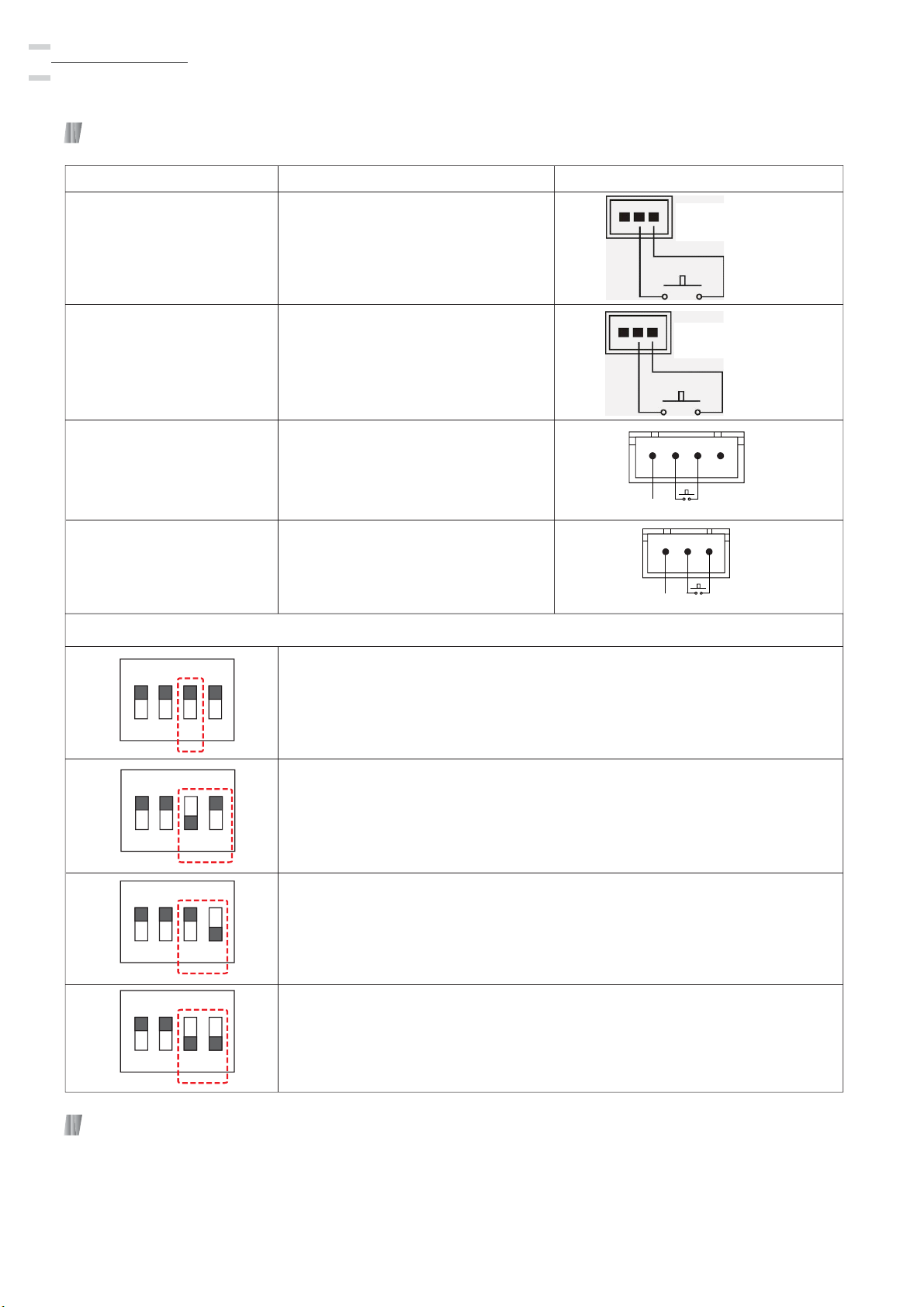
The safety devices (e.g. photocell and emergency stop) must follow the technical safety regulations and
current safety standards, including the limit of forces and speeds.The safety devices must protect any areas
where the risk exists of being crushed, cut or gragged, or where there are any other risks generated by the
motorized door/gate. Apply hazard area notices required by applicable regulations.
Each installation must clearly show the identification details of the motorized door/gate.
Make sure the voltage specified is correct for the device.
Allow at least 10 seconds of rest time between every new cycle to ensure adequate residual current will
return to the power system.
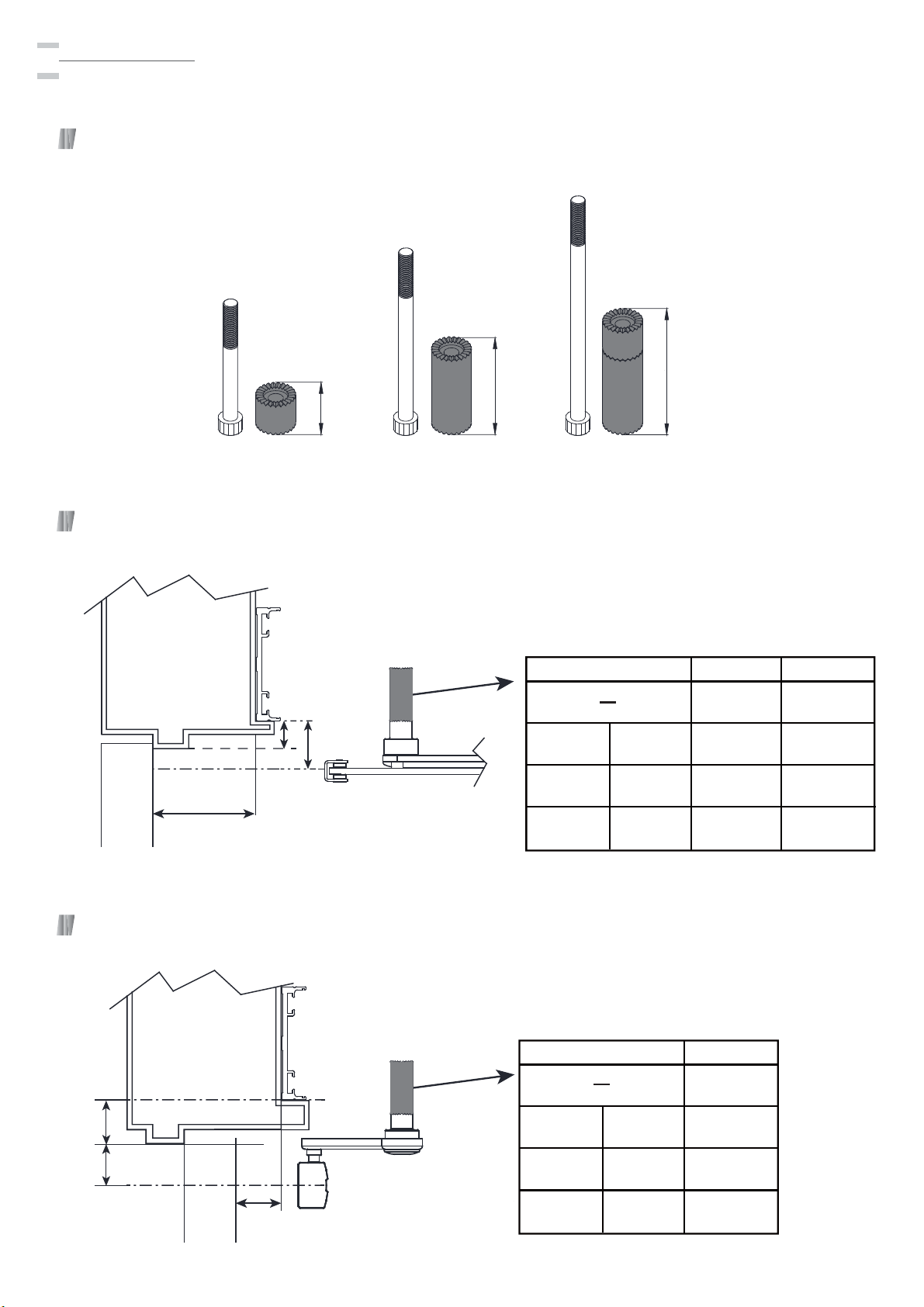
When necessary, connect the motorized door/gate to a reliable earth system with applicable safety
regulations. Before carrying out installation, maintenance and repair, turn off the power supply before opening
the lid to access the electrical parts. To handle electronic parts, wear earthed antistatic conductive gloves.
1
Automatic Door Operator
Manual
1. General Safety Precautions
2. Declaration by Manufacturer
Gianni Industries, Inc.
Address: No. 13, Zhongxing Road, Tucheng District, New Taipei City 236, Taiwan (R.O.C.)
E-mail: [email protected]
Website: www.gianni.com.tw
Herewith declares the following on AD500 Automatic Door Operator for swing doors:
AD500 is one way direction only and used on single doors
AD500 Automatic Door Operator cannot be installed with other mechanical devices (e.g. door closers) except
electric door locks.
UL listed and in conformity with other CE directives: Electromagnetic Compatibility Directive (EN61000) and Low
Voltage Directive (EN 60950-1)
Warranty: 3 years (Factory test: 1 million cycles)
Product should be operated within the recommended door weight range. A reduction in performance is expected
when operating outside of the recommended range.
The performance of the door operator may be affected by different independent variables such as friction, preload
(wind pressure), and other ambient factors. These factors may change the performance of the door operator and
its working life and parts. Furthermore, the surroundings must be considered to ensure the operator’s durability
and smooth operation.

Operating voltage: 100~240 VAC
Automatic Door Operator
Manual
2
3. Product Features
Door weight range: 50~150 kg
Four modes of operation: Auto Mode/ Hold Mode/ Manual Mode/ Push Mode
Obstruction detection - If the door is obstructed during operation, the operator will stop the door
and reverse movement
Backup battery input for emergency power supply
Operates with infrared safety sensors, wall push buttons, card readers, or radio frequency devices
Adjustment of hold-up time, opening/closing speed, and opening angle
Easy integration with electric locking devices and access control systems
Make sure to identify whether the door swing direction is inswing or outswing before installing the door
operator. Use the push arm attachment for outswing doors and the sliding arm and track assembly for
inswing doors.
The AD500 automatic door operator uses a DC motor to open the door. It closes the door by motor
and spring force.
When an opening signal is received by the control unit, the door is opened at the operator-adjusted
opening speed until it reaches the back check position, where it decelerates to a slower speed.
Deceleration
Back Check
Latch Check
Closing Speed
Opening Cycle Closing Cycle
To Fully Opened
Opening Speed
Deceleration To Fully Closed
Outswing Inswing
Push arm
Sliding arm
Track assembly
Hold Open Position

4. Parts Identification
3
Automatic Door Operator
Manual
Cable Hole 2
Door Frame (Outswing)
Door Frame (Inswing)
Cable Hole 1
Cable Hole 4
75mm
236mm
666mm
34mm
36mm
64mm
64mm
36mm
Cable Hole 3
The distance from edge of header to
bottom mounting hole is 1-7/16”(36mm)
when installing on outswing doors.
The distance from edge of header to
bottom mounting hole is 2-1/2”(64mm)
when installing on outswing doors.
Hinge
C
L
Hinge
C
L
Left hand
Outswing Doors
Right hand
Outswing Doors
Right hand
Inswing Doors
Left hand
Inswing Doors
Automatic Door Operator
Template Instructions
P-TL-ARM-500AD Ver.A Publish:2020.06.29
Template
(Operator body)
Template
(Sliding arm)
Template
(Push arm)
30mm
50mm
80mm
100mm
100mm
80mm
50mm
30mm
40mm
Push ARM
Template Instructions
Hinge
Door
Door
Drill 3.3mm hole
300mm
Left hand
Outswing Doors
Right hand
Outswing Doors
CL of Pivot Post
CL of Pivot Post
60mm
CL of Pivot PostCL of Pivot Post
Door Door
580mm
Right hand
Inswing Doors
Left hand
Inswing Doors
Sliding ARMTemplate Instructions
Base plate
Track assembly
Track block
Pivot post
Cover
Motor
Reducer
Sliding arm
Operation
Controller
Push arm
Control unit
X2
X2
X2
X10
X2 X10
X10

Automatic Door Operator
Manual
4
5. Specifications
Operating Voltage
Current Draw
100-240 VAC +10/-15%, 50/60 Hz
3.2A max 77 W, 0.21 - 0.45 A average
Motor Specs
Voltage: 60 VDC
Maximum current: 2 A
Power consumption: 98 W
Maximum rotation frequency: 2900 RPM
Maximum Torque Output 40 NM
Opening Time (0° - 90°) Variable between 5 - 8 seconds
Closing Time (90° - 10°) Variable between 12 - 25 seconds
Hold Open Time Selectable 3, 10, 20, 30 seconds
Battery Requirement 24 VDC, 8A
Door Width
Door Weight 50 - 150 kg (110-331 lbs)
Electric Locks Power Input 24VDC, max. 250mA
Operating Temperature -4 °F to +113 °F (-20 °C to +45 °C)
Relative Humidity
(non-condensing) Max 85%
Maximum Degree of Opening 80° - 120°
Net Weight 13.3 kg (30 lbs)
Operator Body Dimensions 716(L) X 131(W) X 110(D) mm
Sliding Arm Length 15 3/4” (400 mm)
Door Height 110 1/4” (2800 mm)
Track Assembly Length 24 7/16” (620 mm)
28 3/16” (L) X 5 3/16” (W) X 4 5/16”(D)
29 1/2”-47 1/4” (750-1200 mm)
28 3/16” (716mm)
(110mm)
(375mm)
(618mm)
24 5/16”
4 5/16”
14 3/4”
5 3/16” (131mm)
1 1/8” (29mm)

Relay
Relay
Relay
Relay
Back Check / Latch Check Angle
Closing Speed
Opening Speed
(Device 2 Input)
Motor
Encoder
Backup Battery Input
Closing door direction
Opening door direction
Make sure the voltage
specified is correct for
the device.
For safety, we recommend using a
fail-safe electric lock in case of
emergencies or power interruptions.
D21
D17
D18
5
Automatic Door Operator
Manual
Activation
(Device 1 Input)
AutoHold
Push
&
GoManual
81234
5
67
(Device 3 Input)
P
P2P1
Auto
Auto
COM.
Hol
d
d Open
Push&GO
Manual
P1 P2
Black
Red
Blue
Green
White
P2
P1
IR Sensor Input
24VDC
Output
COM
Electric Locking
Device
(Fail-Safe)
OPB-500AD
Operation Controller
Call Point
N.O. COM COM
N.O.
Smoke Detector
(or Fire Panel)
Activation
SVR 1
SVR 2
SVR 3
(24VDC)
(24VDC)
Back-up battery ensures normal
operation when power fails.
D8
Battery cannot be connected
to the uninterruptible power
supply system for the
building.
AD500-DB interlock module
Master door opens first and closes last. Slave door opens second and closes first.
Master Door Slave Door
Control Unit

Automatic Door Operator
Manual
6
Functions on the Control Unit
1234
ON Position 3 ON
1234
ON
1234
ON
Position 3 OFF
Position 4 ON
Position 3 ON
Position 4 OFF
1234
ON Position 3 OFF
Position 4 OFF
Adjusting hold open time
Hold open for 3 seconds
Hold open for 10 seconds
Hold open for 20 seconds
Hold open for 30 seconds
+-
+-
Function Description Diagram
Activation Input 2
Operator is activated by
Activation Device 2.
Activation Input 3
Operator is activated by
Activation Device 3.
Infrared Sensor Input
(Closing door direction)
Monitoring of IR impulse
or detection
(Use the included 4-pin, 3-wire
red/white/black harness)
Infrared Sensor Input
(Opening door direction)
Monitoring of IR impulse or
detection
(Use the included 3-pin, 3-wire
red/white/black harness)
Activation Device 2
Activation Device 3
(Use the included 2-pin red, or
black wire harness)
(Use the included 2-pin red, or
black wire harness)
LED Indicator
D8 (Green light): Power indicator
D17/18 (Red light): Door position indicator light. After supplying power, the red light turns on and then
off, indicating door position detecting is completed to proceed the learning mode.
D21 (Yellow light): Lit when door is locked; off when door is unlocked.

7
Automatic Door Operator
Manual
6. Before Installation
For security and vandalism prevention, always mount the operator access in the interior of a building
whenever possible.
This product is used only for single door applications. The AD500-DB automatic operator is used on
double doors.
Examine the indoor and outdoor wind pressure before installing the AD500. To assure the proper
operation and the best performance, please make a regular check of your operator.
Make sure that the door leaf is properly reinforced at the installation points.
Consider all power wire entry locations and signaling wires before preparing for installation.
Stand with your back against the hinges. If door opens at your left side, it is left-handed. If door opens
at your right side, it is right-handed. Right Hand shown in the diagram.
Make sure to identify the door swing direction, whether left hand or right hand, and inswing or outswing.
The operator must be installed inside of the room.
left hand outswing doors right hand outswing doors
left hand inswing doors right hand inswing doors
Outdoor
Indoor
Outdoor
Indoor
Outdoor Outdoor
Indoor
Indoor

Automatic Door Operator
Manual
8
Pre-Setup Evaluation
1.The AD500 is used for single door applications. For double door applications, use the AD500-DB
(2 units of AD500 door operators including an interlock module) to program the master and slave
door. The master door opens first and then closes last while the slave door opens second and closes
first. The double operator cover needs to be ordered specially.
2.When installing on outswing doors, there must be space at least 13 cm above the door header.
When installing on inswing doors, there must be space at least 16 cm above the door header.
3.The required door leaf width is at least 75 cm (minimum 80 cm wide door frame) at this time the
electromagnetic lock can only be installed upright.
4.It is strongly recommended to install on concrete or brick walls. For wood plates or partition boards,
add a piece of reinforced metal plate to hold the operator weight or prevent shaking when opening
or closing the door.
5.Note that this product cannot be installed on frameless glass doors or walls, sliding doors, and gates.
6.Install shaft extensions (DT-20/50/70) if the frame stop exceeds standard length (see measurement A
and C on page 10). If the frame stop exceeds 40 mm length to contact with pivot post, add spacers to
compensate for gaps and no shaft extensions are required.
7.For outswing applications: if the door frame and leaf depth (X) exceed 150 mm (see the illustration on
page 9), the lengthen arm must be used. The maximum depth (X) of the lengthen arm does not exceed
300 mm.
8.For inswing applications, the door leaf and frame depth do not exceed 70 mm (see the illustration on
page 10).
9.Check if the door moves smoothly and the hinges can carry the door load. If the door hinges are
warped, adjust the hinges first and then install the door operator.
10.The existing floor hinges or mechanical door closer needs to be removed.
11.The existing mechanical latch needs to be removed.
12.The existing door handle needs to be removed. (when using this product, it is strictly forbidden to
push or pull the door)
13.It is not recommended to install on exterior doors or gates.
14.This product closes the door electrically. When closing the door, there will be a slight collision sound.
Attach a door frame silencer if necessary.
15.It is suggested to install electromagnetic lock to prevent the door from being opened by force under
wind load conditions or access control.

9
Automatic Door Operator
Manual
Push Arm
Use the push arm for outswing doors. Use the lengthen arm If the depth (“X”) exceeds 150 mm. For
lengthen arm, the “X” maximum depth cannot exceed 300 mm.
Push Arm Extensions
Standard Arm Dimensions
P/N : ARM-500AD-3
P/N : ARM-500AD-3L
Reveal =X Extension
Up to 5-15/16” (0-150mm) Standard arm
5-15/16” to 11-13/16”(150-300mm) Lengthen arm
X
Lengthen Arm Dimensions
(30mm)
1 3/16”
(30mm)
1 3/16”
(30mm)
1 3/16”
Ø1/4” (6.3mm)
2 3/8” (60mm)
2 3/8” (60mm)
2 3/8” (60mm)
2 3/8” (60mm)
(20mm)
13/16”
(5.2mm)
Ø3/16”
1 3/4” (45mm)
10” (254.5mm)
Ø1/4” (6.3mm)
(30mm)
1 3/16”
(30mm)
1 3/16”
(30mm)
1 3/16”
2 3/8” (60mm)
2 3/8” (60mm) 2 3/8” (60mm)
12 3/8” (314.5mm)
10 5/16” (261.5mm)
9 3/16” (234mm)
11/16” (17.5mm)
(10mm)
3/8”
(30mm)
1 3/16”
(30mm)
1 3/16”
9 13/16” (250mm)
10 5/16” (261.5mm)
9 3/16” (234mm)
11/16” (17.5mm)
(10mm)
3/8”
12 3/16” (310mm)
(30mm)
1 3/16”
(30mm)
1 3/16”
(15mm)
9/16”

Automatic Door Operator
Manual
10
Drive Shaft Extension Kits
Operator with Push Arm System
Operator with Sliding Arm System
AB
C
2 3/4” (70mm)
2” (50mm)
13/16” (20mm)
P/N : DT-50 P/N : DT-70 (DT-20+DT-50)P/N : DT-20
≤300mm
P/N
AB
0 ~ 30mm 50mm
30 ~50mm 70mm
50 ~80mm 100mm
80~ 100mm 120mm
DT-20
DT-50
DT-70
20mm
50mm
70mm
P/N
C
0 ~37mm
37 ~57mm
57 ~87mm
87 ~107mm
DT-20
DT-50
DT-70
20mm
50mm
70mm
≤31.8mm
≤70mm
Shaft extensions are used for specific door frames.

11
Automatic Door Operator
Manual
Required Tools
Removing the Cover & Reducer
Remove the reducer by
loosening 4 screws.
Center Punch
6mm Allen Wrench (included)
5mm Allen Wrench (included)
4mm Allen Wrench (included)
Torx Wrench (5mm)
Drill Bit -(9.5mm)
Drill Bit -(5.1mm)
Drill Bit -(4mm)
Masonry Drill Bit (5mm)
Spanner (12mm)
TAPS (6mm)
T-Handle Tap Wrench
Phillips Screwdriver
Flathead Screwdriver
Hammer
Spirit Level
Electric Drill (Pro)
Unplug the signaling wires and
power wire for the motor.

Automatic Door Operator
Manual
12
7. Template Instructions
Left hand
Outswing Doors
7-1
7-2
7-3
Directions: Check the door hinge centerline, and the two reference lines that are 36 mm
away from the bottom line of the header frame.
Directions: Mark the 8 screw positions by center punch.
Indoor
Outdoor
36mm
C/L
Directions: Template placement as illustrated.
Door Frame (Outswing)
36mm
36mm
The distance from edge of header to
bottom mounting hole is 1-7/16”(36mm)
when installing on outswing doors.
Hinge
C
L
Left hand
Outswing Doors
Automatic Door Operator
Template Instructions
36mm
Note the centerline of hinge on the template.

13
Automatic Door Operator
Manual
7-4
7-5
7-6
Directions: Check the door hinge centerline, and the two reference lines that are 36 mm
away from the bottom line of the header frame.
Directions: Template placement as illustrated.
Directions: Mark the 8 screw positions by center punch.
Right hand
Outswing Doors
Outdoor
Indoor
36mm
C/L
Door Frame (Outswing)
36mm
The distance from edge of header to
bottom mounting hole is 1-7/16”(36mm)
when installing on outswing doors.
Hinge
C
L
Hinge
C
L
Right hand
Outswing Doors
Automatic Door Operator
Template Instructions
36mm
Note the centerline of hinge on the template.

Automatic Door Operator
Manual
14
7-7
7-8
7-9
Directions: Check the door hinge centerline, and the two reference lines that are 64 mm
away from the bottom line of the header frame.
Directions: Mark the 8 screw positions by center punch.
Left hand
Inswing Doors
Directions: Template placement as illustrated.
Door Frame (Inswing)
64mm
64mm
The distance from edge of header to
bottom mounting hole is 2-1/2”(64mm)
when installing on outswing doors.
Hinge
C
L
Left hand
Inswing Doors
Automatic Door Operator
Template Instructions
64mm
C/L
64mm
Outdoor
Indoor
Note the centerline of hinge on the template.

7-10
7-11
7-12
Directions: Check the door hinge centerline, and the two reference lines that are 64 mm
away from the bottom line of the header frame.
Directions: Template placement as illustrated.
Directions: Mark the 8 screw positions by center punch.
Right hand
Inswing Doors
15
Automatic Door Operator
Manual
Door Frame (Inswing)
64mm
64mm
The distance from edge of header to
bottom mounting hole is 2-1/2”(64mm)
when installing on outswing doors.
Hinge
C
L
Right hand
Inswing Doors
Automatic Door Operator
Template Instructions
64mm
C/L 64mm
Indoor
Outdoor
Note the centerline of hinge on the template.

8. Installation Preparation by Frame Types
Automatic Door Operator
Manual
16
8-1 Hollow Metal Frames
54
321
Use blind nuts for reinforcement. Drill 9.5mm holes. Hammer blind nut assembly. Tighten with a 12 mm
C type wrench and a 5 mm Allen wrench. Remove the tools. The blind nut is countersunk into the metal
plate. The operator base plate is secured to the frame.
Installing Blind Nuts
Blind Nut Assembly

17
Automatic Door Operator
Manual
8-2 Reinforced Metal Frames
If installing on thin wood or partition boards, a thicker metal plate needs to be added to enhance
the sturdiness of the installation site.
Drill 5.1 mm holes and tap with 6 mm drill bit. Secure the base plate to the frame.
8-3 Solid Wood Frames
For solid wood frames. Drill 4 mm holes first. Fix Phillips screws.
Secure the base plate to the frame.
8-4 Concrete Walls
Drill with 5 mm masonry drill bit.
Fix Phillips screws. Secure the base plate to the frame.

Automatic Door Operator
Manual
18
9. Base Plate & Reducer Installation
9-1 Left Hand Outswing Doors
Left hand
Outswing Doors
9-2 Right Hand Outswing Doors
Right hand
Outswing Doors
Secure the base plate to the door frame. Reducer is secured to the base plate with 4 screws.
Please see below instructions for each door swing direction. Reducer opening angle ranges
from 0 to 90 degrees.
Other manuals for AD500
1
Table of contents
Other GEM Door Opening System manuals
Popular Door Opening System manuals by other brands

Dormakaba
Dormakaba ED100 operating & maintenance manual

Relcross
Relcross 9130 installation instructions

Kesseböhmer
Kesseböhmer eTouch DISPENSA operating instructions

EZ-ACCESS
EZ-ACCESS CONCIERGE 23DL installation manual

Von Duprin
Von Duprin 35A-F installation instructions

Von Duprin
Von Duprin 98/9927 installation instructions