Page 2
INTRODUCTION
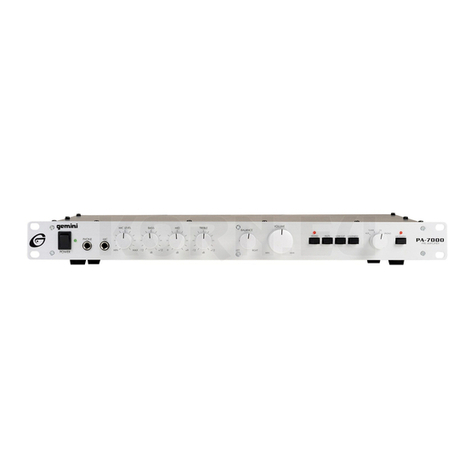
Congratulations on purchasing a Gemini model PA-701 rack mountable
preamplifier. This state of the art unit includes the latest features backed by a
three year warranty. Prior to use, we suggest that you carefully read all the
instructions.
CAUTIONS
1. All operating instructions should be read before using this equipment.
2. To reduce the risk of electrical shock, do not open the unit. There are NO
USERREPLACEABLEPARTSINSIDE.Pleasereferservicingtoaqualified
service technician.
3. Do not expose this unit to direct sunlight or to a heat source such as a
radiator or stove.
4. This unit should be cleaned only with a damp cloth. Avoid solvents or other
cleaning detergents.
5. When moving this equipment, it should be placed in its original carton and
packaging. This will reduce the risk of damage during transit.
6. DO NOT EXPOSE THIS UNIT TO RAIN OR MOISTURE.
7. DONOTUSEANYSPRAYCLEANERORLUBRICANTONANYCONTROLS
ORSWITCHES.
CONNECTION
1. Be sure the POWER (1) switch is in the OFF position. All connections must
be made with all equipment OFF.
2 . For best sound, use only high quality RCA cables when hooking up
equipment to the PA-701. Make sure that all cables are pushed in securely.
3. Connect the OUTPUT LINE (22) jacks of the PA-701 to your amplifier(s).
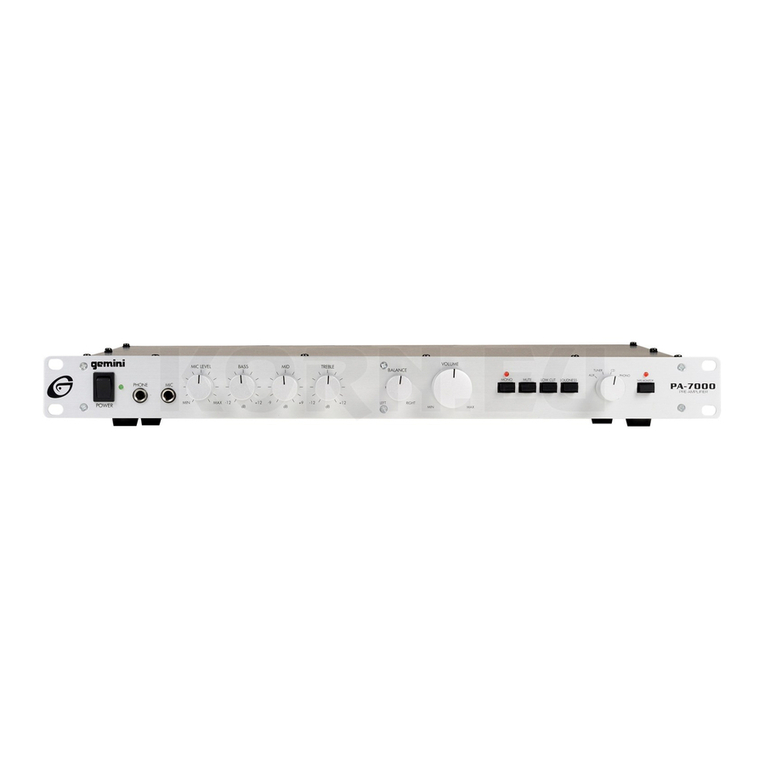
4. Plug your microphone into the MIC (5) jack on the front panel of the
PA-700.
5. Plug your headphone into the PHONE (11) jack on the front panel.
6. Plug your turntable into the PHONO (16) jacks and attach the ground wire
from the turntable to the GND (23) screw.
7. Plug your CD player into the CD (17) jacks.
8. Plug your tuner into the TUNER (18) jacks.
9. Any other line level output device (such as a mixer) may be connected to
the AUX (19) jacks.
10.You will require two sets of RCA cables to connect your tape deck to the
PA-701. Use one set of RCA cables to connect the tape deck’s playback
or output jacks to the PLAY (20) jacks on the rear of the PA-701. Use the
other set of RCA cables to connect the tape deck’s record or input jacks to
the REC (21) jacks on the PA-701.
NOTE: Any line level device can be connected to the PLAY (20) jacks and
then can be accessed by the TAPE MONITOR (3) button.
OPERATION
1. POWER: Once you have made all source connections to the PA-701, and
you have made sure that the VOLTAGE SELECTOR (24) switch is in the
proper position, plug the power cord into a power source and press the
POWER (1) button (LED lights).
2. INPUT SELECTION: The INPUT SELECTION (2) switchdetermines which
inputsource goes through the PA-701 to the amplifier.IfthePHONOposition
is selected on the INPUT SELECTION (2) switch, then the source
connected to PHONO (16) jackonthe back panelwill be selected.If the CD
position is selected, then the source connected to the CD (17) jack on the
back will be selected.
3. TAPE MONITOR: Pressing the TAPE MONITOR (3) button (the LED is lit)
allows you to hear the playback signal of your tape deck or whatever you
have connected to the PLAY (20) jacks on the rear panel. Pressing the
TAPE MONITOR (3) button a second time (the LED is off), disengages the
tape monitor circuit.
4. MIC LEVEL: The MIC LEVEL (4) control adjusts the volume of the
microphone.
5. MIC JACK: 1/4" microphone input jack (5).
6. VOLUME: Overall volume is controlled by the VOLUME (6) control.
7. BALANCE: Use this control to adjust the relative levels of the left and right
channels. The 12 o’clock position is the point of equal BALANCE (7).
8. TREBLE: The TREBLE (8) control adjusts the relative level of the high
frequencies in the sound.
9. MID: The MID (9) control adjusts the relative level of the mid range
frequencies in the sound.
10.BASS: The BASS (10) control adjusts the relative level of the low
frequencies in the sound.
11. PHONE JACK: 1/4" headphone input jack (11).
12.MONO: When the MONO (12) buttonisactivated (LED islit),the two stereo
channels are blended together to produce monophonic sound. This blend
minimizes rumble and surface noise in old monophonic records. Push the
button a second time (LED goes out) to get back to stereo mode.
13.MUTE: Pushing this button reduces the volume of the amplifier output
signal by approximately 20 dB. Pressing the button a second time removes
the muting. The MUTE (13) has no effect on the microphone volume.
14.LOWCUT:Theoutputfrom a turntable usually contains strongbut inaudible
impulses at infrasonic frequencies (below 20Hz) due to disc warps,
stylus/tonearm resonance, and vibrations that reach the turntable. If these
are amplified at full strength, they may waste amplifier power and muddy
thesound.TheLOW CUT FILTER (14) attenuates these unwanted signals.
15.LOUDNESS: When pressed, the LOUDNESS (15) button engages a
“loudness compensation” circuit which, at low-to-medium volume, boosts
the bass and treble response.
USING THE GROUND LIFT SWITCH
Depending on your system configuration, sometimes applying the ground will
createa quieter signalpath. Sometimes liftingthe ground caneliminate ground
loops and hum to create a quieter signal path.
1. With the unit on, listen to the system in idle mode (no signal present) with
the ground applied (the GROUND LIFT SWITCH (25) in the left position).
2. Then turn the power off before moving the GROUND LIFT SWITCH
(25). Lift the ground by moving the GROUND LIFT SWITCH to the right,
turn the power back on and listen to determine which position will provide
a signal devoid of background noise and hum. Keep the GROUND LIFT
SWITCH in the ground position if the noise level remains the same in either
position.
CAUTION: Do not terminate the AC ground on the unit in any way. Termination
of the AC ground can be hazardous.
SPECIFICATIONS
INPUTS SENSITIVITY/IMPEDANCE
Mic..................................................................................................1mV / 3 Kohms
Phono.........................................................................................3mV / 47 Kohms
Tape,Tuner,CD, Aux......................................................................150mV / 22 Kohms
OUTPUT/IMPEDANCE
Tape Rec.....................................................................................150mV / 3 Kohms
Pre Output..................................................................................max. 11V / 1 Kohms
TOTAL HARMONICDISTORTION
Mic................................................................................................less than 0.02%
Phono...........................................................................................less than 0.04%
Tape,Tuner,CD, Aux................................................................less than 0.01%
SIGNAL TO NOISE RATIO
Mic.........................................................................................more than 70dB
Phono....................................................................................more than 90dB
Tape,Tuner,CD, Aux............................................................more than 100dB
GENERAL
Frequency Response..................................................5Hz - 30 KHz +0, - 3dB
Bass..........................................................................................+/-12dB at 100Hz
Midrange..........................................................................................+/-9dB at 1KHz
Treble..................................................................................+/-12dB at 10KHz
Loudness.........................................................................+9/0/+9dB at 100/1K/10KHz
Mute........................................................................................................-20dB
Power.........................................................................120V or 230V, 50/60Hz
Power Consumption....................................................................................15W
Dimensions...................................................................483mm x 45mm x 248 mm
19" x 1.75" x 9.75"
Weight................................................................................................4 kg (9 lbs.)
