Gemini PMX-1400 User manual

(1)
SERVICE MANUAL
PMX-1400
Stereo Preamp Mixer
CONTENT’S:
Connections & Operations:............................................................Page 2-5
Specifications:.....................................................................................Page 5
Parts Lists:........................................................................................Page 5-6
PCBs:................................................................................................Page 7-9
Schematics...................................................................................Page 10-11
Gemini Sound Products Corp.
120 Clover Place P.O. Box 6928
Edison, NJ 08818-6928
732-738-9003 (Phone) • 732-738-9006 (Fax)

(2)
PMX-1400

(3)
47
46
46
44
49
45
45
43
43
41
42
42
40
40
39
39
38
38
37
37
36
36
35
35
34
34
50
33
L7 L6 PH3
L5
L8
REC
BOOTH
AMP
+++
+
+
+
+
+
+
123
1
2
3
123
GND LIFT
RIGHT LEFT
MAIN POWER
+
PH1
L1
L1 PH1
PH2
PH3 L3
L2
PH2
L3
L4
L5
+
+
99
99
123
1
2
3
123
48

(4)
INTRODUCTION:
Congratulations on your purchase of the Gemini PMX®-1400 Mixer.
This state-of-the-art unit is backed by a three year warranty, excluding
crossfader and channel slides. Prior to use, we suggest that you
carefully read all the instructions.
FEATURES:
• 4 Stereo Channels
• Talkover
• State-of-the-Art Cue Section
• Dual 7 Band Graphic Equalizers
• Booth and Record outputs
• Balanced and Unbalanced Master Outputs
• 3 Phono/Line Convertible, 5 Line, and 2 Mic Inputs
CAUTIONS:
1. All operating instructions should be carefully read before
using this equipment.
2. To reduce the risk of electrical shock, do not open the unit.
THERE ARE NO USER REPLACEABLE PARTS INSIDE.
Please refer servicing to a qualified service technician.
In the USA: If you experience problems with this unit,
please call 1 (732) 969-9000 for Gemini Customer Service.
Do not attempt to return this equipment to your dealer.
3. Do not expose this unit to direct sunlight or to a heat source
such as a radiator or stove.
4. This unit should be cleaned only with a damp cloth. Avoid
solvents or other cleaning detergents.
5. When moving this equipment, it should be placed in its original
carton and packaging. This will reduce the risk of damage
during transit.
6. DO NOT EXPOSE THIS UNIT TO RAIN OR MOISTURE.
7. DO NOT USE SPRAY CLEANER OR LUBRICANT ON CONTROLS
OR SWITCHES.
CONNECTIONS:
1. Before plugging the power cord in, make sure that the VOLTAGE
SELECTOR (33) switch is set to the correct voltage.
NOTE: THIS PRODUCT IS DOUBLE INSULATED AND IS NOT INTENDED TO
BE GROUNDED.
2. Make sure that the POWER (26) switch is in the OFF position.
The POWER LED (27) display will be off.
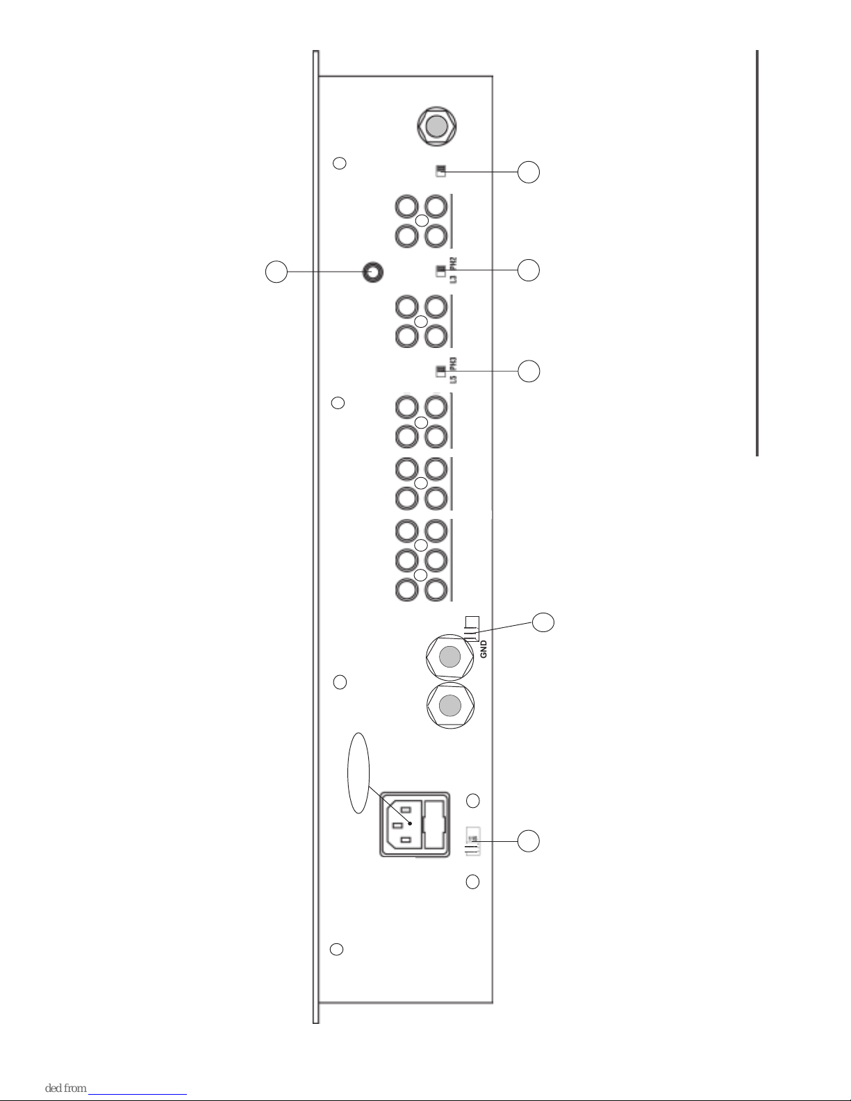
3. The PMX-1400 is supplied with four sets of output jacks: The MAIN
OUTPUT (34) jacks connect to the main amplifier. The BALANCED
MASTER OUTPUT (99) jacks connect the mixer to main amplifier
using standard cables with 1/4” connectors. We recommend using
balanced cables if the distance to your amp is 10 feet or more. The
REC OUTPUT (36) jacks can be used to connect the mixer to the
record input of your recording unit, thus enabling you to record your
mix. The BOOTH OUTPUT (35) jacks allow the connection
of an additional amplifier.
4. The MIC 1 input (located on the front panel) accepts an XLR
connector. The MIC 2 (48) input (on the rear panel) accepts
1/4" connectors. All accept balanced and unbalanced microphones.
5. On the rear panel are three stereo PHONO/LINE (40, 43, 46) inputs
and five stereo LINE (37, 38, 39, 42, 45) inputs: PHONO/LINE
SWITCH (41) enables you to set the (40) input to Phono or Line.
PHONO/LINE SWITCH (44) enables you to set the (43) input to
Phono or Line. PHONO/LINE SWITCH (47) enables you to set the
(46) input to Phono or Line. Attach phono ground line to the
GROUND THUMB SCREW (49).
7. Headphones may be plugged into the front panel mounted
HEADPHONE (32) jack.
8. The PMX-1400 comes with a front panel BNC LIGHT (25) jack
for use with a (not provided) gooseneck light.
USING THE GROUND LIFT SWITCH:
Depending on your system configuration, application of the ground
will sometimes create a quieter signal path. Lifting the ground
occasionally eliminates ground loops and “hum” to create a quieter
signal.
1. With the mixer ON, listen to the system in “idle” mode (no signal
present) and with the ground “applied” and the GROUND LIFT
SWITCH (50) in the LEFT position.
2. Turn the power OFF before moving the GROUND LIFT
SWITCH (50). “Lift” the ground by moving the GROUND LIFT
SWITCH to the RIGHT, turn the power back ON and listen to
determine which position provides a signal devoid of background
noise and hum. Keep the GROUND LIFT SWITCH in the “ground”
position if the noise level remains the same in either position.
CAUTION: DO NOT TERMINATE THE AC GROUND ON THE MIXER.
CABLE. TERMINATION OF THE AC GROUND CAN BE HAZARDOUS!
OPERATION:
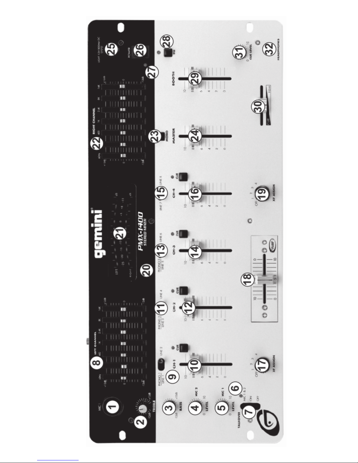
1. POWER: Once you have made all the equipment connections to
your mixer, press the POWER SWITCH (26). The power will turn
on and the POWER LED (27) will glow RED.
2. CHANNEL 1: Switch (9) allows you to select PHONO 1/LINE 1
(46) or the LINE 2 (45) input. CHANNEL SLIDE (10) controls
the input level of this channel.
3. CHANNEL 2: Switch (11) allows you to select PHONO 2/LINE 3
(43) or the LINE 4 (42) input. CHANNEL SLIDE (12) controls
the input level of this channel.
4. CHANNEL 3: Switch (13) allows you to select PHONO 3/LINE 5
(40) or the LINE 6 (39) input. CHANNEL SLIDE (14) controls
the input level of this channel.
5. CHANNEL 4: Switch (15) allows you to select either the LINE 7
(38) or LINE 8 (37) input. CHANNEL SLIDE (16) controls
the input level of this channel.
6. CROSSFADER: The CROSSFADER (18) allows the mixing of one
source into another. The PMX-1400 features an assignable
crossfader. The ASSIGN (17, 19) switches allow you to select
which channel will play through each side of the crossfader.
7. ASSIGN (17) switch has five settings (OFF, 1, 2, 3 and 4) and
allows you to direct Channel 1, 2, 3 or 4 through the LEFT side
of the crossfader. ASSIGN switch (19) also has five settings
(OFF, 1, 2, 3 and 4) and allows you to direct Channel 1, 2, 3 or 4
through the RIGHT side of the crossfader. Placing either ASSIGN
switch in the OFF position inactivates that side of the crossfader.
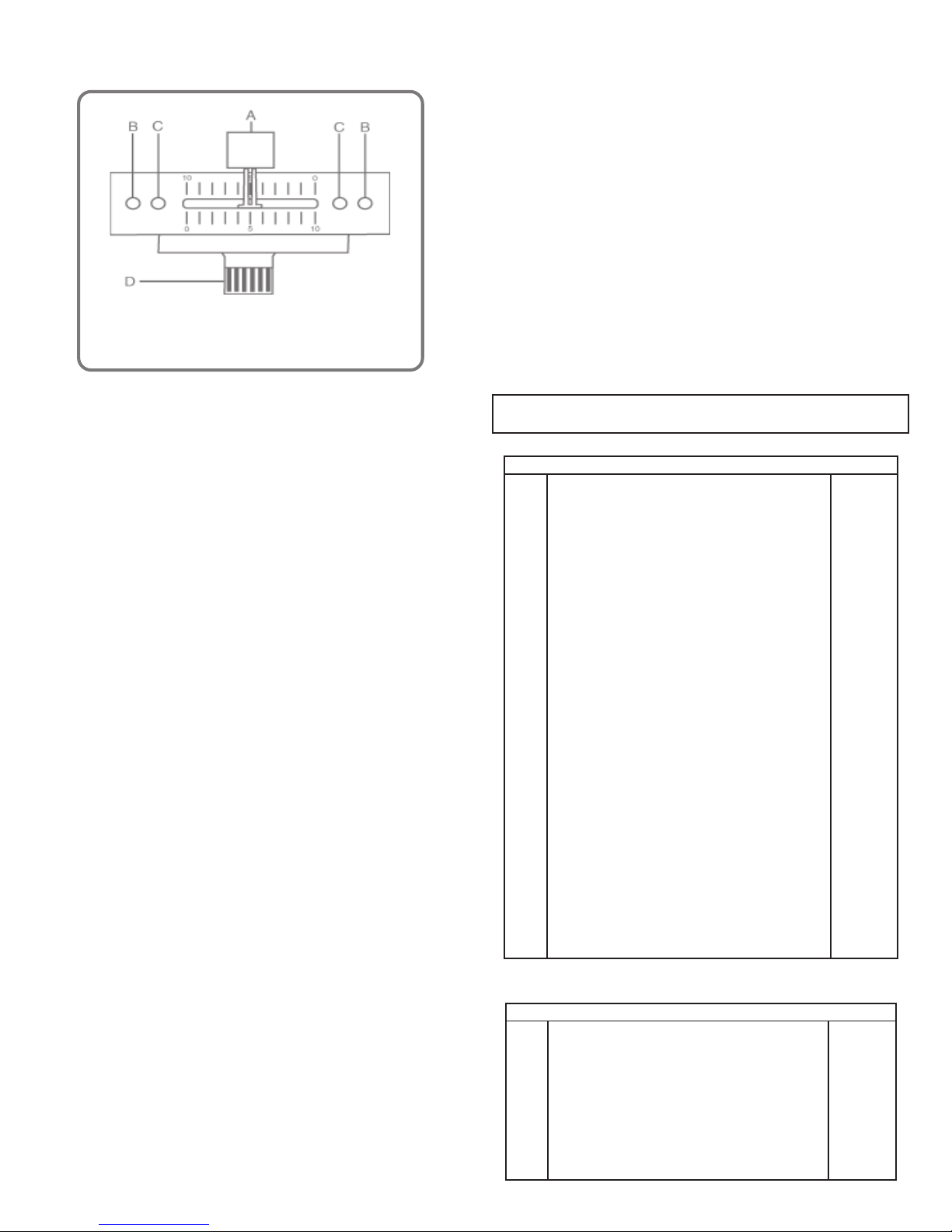
The CROSSFADER in your unit is removable and, should the need
arise, can be easily replaced. Replacement crossfaders are
available in three models: the RG-45 PRO (RAIL GLIDE™) Dual-
Rail Crossfader; as well as RF-45, which has a 45mm travel
from side-to-side; and the PSF-45, which features a special
“curve” designed for scratch mixing. Your Gemini mixer is equipped
with an RG-45 PRO (RAIL GLIDE™) 45MM DUAL-RAIL CROSSFADER
featuring internal dual stainless steel rails that allow the slider to ride
smoothly and accurately from end-to-end.

(5)
The following instructions are provided for those who
purchase a crossfader replacement unit from an authorized
Gemini dealer:
8. EQUALIZER: This unit features dual 7 band GRAPHIC EQUALIZERS
(8, 22) that allow you to adjust the sound to fit any room. Activate
the equalizer by pressing EQ BUTTON (28) (EQ LED is illuminated).
By adjusting any of the 7 LEFT equalizer slide controls (8), you can
cut or boost the tonal characteristics of the sound coming from the
LEFT speaker by ±12 dB. Adjusting any of the 7 RIGHT equalizer
slide controls (22) allows you to cut or boost the tonal
characteristics of the sound coming from the RIGHT speaker by ±12
dB. Deactivate the equalizer by pressing the EQ BUTTON (28) again
(EQ LED is OFF).
9. OUTPUT CONTROL: The level of the MAIN OUTPUT (34) is
controlled by the MASTER (24) slide. Activating the MONO (23)
button (MONO LED is illuminated) converts the overall output to
mono. The BOOTH (29) control adjusts the level of the BOOTH
OUTPUT (35).
HINT: BOOTH OUTPUT IS USED BY SOME DJS TO RUN
MONITOR SPEAKERS IN THE DJ BOOTH. IT IS ALSO USED AS
A SECOND ZONE OR AMP OUTPUT.
NOTE: REC OUTPUT HAS NO LEVEL CONTROL. LEVEL IS
CONTROLLED WITH THE CHANNEL SLIDES OF THE SELECTED
CHANNEL(S). TONE IS CONTROLLED VIA THE EQUALIZERS.
10.TALKOVER: The purpose of the talkover is to allow the program
playing to be muted so that the mic may be heard above the music.
The MIC/TALKOVER SWITCH (7) controls MIC 1 and MIC 2 and
has three settings.
• When MIC/TALKOVER (7) is in the BOTTOM position,
MIC 1, MIC 2 and TALKOVER are all OFF.
•When MIC/TALKOVER (7) is in the CENTER position, MIC 1
and MIC 2 are ON. MIC INDICATOR (6) glows/TALKOVER is OFF.
•When MIC/TALKOVER SWITCH (7) is in the TOP position,
MIC 1, MIC 2 and TALKOVER are ON and the volume of all
sources except MIC inputs is lowered by 16 dB.
11. TREBLE (2) and BASS (3) controls allow you to adjust the tone
of MIC 1 and MIC 2. MIC 1 LEVEL (5) controls the level of MIC 1
while MIC 2 LEVEL (4) controls the level of MIC 2.
12.CUE: By connecting a set of headphones to the HEADPHONE (32)
jack, you can monitor any or all channels. Press CUE ASSIGN (20)
buttons for Channels 1 through 4 and select the Channel(s) to be
monitored. The respective LED indicators will glow. Use the CUE
LEVEL (31) control to adjust the cue volume without changing the
overall mix. By moving the CUE PGM PAN (30) control to the LEFT
you will be able to monitor the assigned cue signal. Moving the
control to the RIGHT allows you to monitor PGM (program) output.
13.DISPLAY: The DISPLAY (21) indicates the MASTER output of the
left and right levels.
SPECIFICATIONS:
INPUTS:
Phono........................................................................................3 mV, 47 KOhm
Line........................................................................................150 mV, 27 KOhm
MIC 1 & MIC 2...............................................................1.5 mV, 2 K Ohm
Balanced
Bass....................................................................................................± 12dB
High......................................................................................................± 12dB
OUTPUTS:
Amp/Booth................................................................................0 dB 1V, 400
Ohm
Max........................................................................................20V Peak-to-Peak
Rec......................................................................................225 mV, 5 KOhm
GENERAL:
Frequency Response......................................................20Hz - 20KHz +/- 2 dB
Distortion...........................................................................................0.02%
S/N Ratio...............................................................................Better than 80 dB
Talkover Attenuation................................................................................-16 dB
Headphone Impedance...........................................................................16 Ohm
Echo......................................................................................600m sec
Power Source.....................................................115/230V, 50/60Hz, 10W
Dimensions..............................................19”w x 4”d x 9”h (483 x 94 x 221 mm)
Weight..................................................................................10.17 lbs. (4.6 Kg)
••
••
•Unscrew the FADER PLATE SCREWS (B).
••
••
•Do not touch the INSIDE SCREWS (C).
••
••
•Carefully lift the fader and unplug the CABLE (D).
••
••
•Plug the new fader into CABLE (D) and place it back in the mixer.
••
••
•Screw the fader to the mixer with the FADER PLATE SCREWS (B).
Description Part #
Cabinet Parts and Packing
1
2
4
5
6
7
8
9
10
11
12
13
14
15
16
17
18
19
20
21
22
23
24
25
26
27
28
29
30
31
32
Item #
Parts Lists:
FACEPPMX1400
021-999
032-007
021-767
022-322
022-305
023-674
002-531
002-532
002-703
002-724
002-726
003-102
003-110
148-312
003-994
003-970
003-373
003-969
003-986
003-975
003-564
047-474
049-206
159-201
159-167
159-216
159-171
159-196
146-710
101-008
PANEL CONTROL
PANEL REAR
COVER BOTTOM
BRACKET VR
HOLDER X-FADER
PROTECTOR PLATE FOR 115/230V SWITCH
SWING LEVEL
KNOB PUSH (SMALL)
BUSHING FOR KNOB (SMALL)
KNOB SLIDE (SMALL)
KNOB SLIDE SILVER (BIG)
KNOB SLIDE SILVER (SMALL)
KNOB ROTARY (ASSIGN)
KNOB ROTARY (B)
KNOB INLAY (SILVER); LEVEL, BALANCE, CUE, ASSIGN
EQ VR INLAY
TRIM VR
INLAY PLATE
HOLDER LED 3f LED(17mm)
HOLDER LED
HOLDER LED
WASHER XLR
PCB SPACER SUPPORT
PAD FOOT
BNC DUST PROOF CLOTH
DUST PROOF CLOTH (VR)
DUST PROOF CLOTH (KNOB-SWING)
DUST PROOF CLOTH (VR)
FADER DUST PROOF CLOTH
GND SCREW
FLAT-HEAD MACHINE SCREW; FMS 2X4 (Y)
262-044
262-045
262-046
262-052
262-053
PRINTED CIRCUIT BOARD PDM24S-1:IN/OUT
PRINTED CIRCUIT BOARD PDM24S-2:MAIN
PRINTED CIRCUIT BOARD PDM24S-4:
FADER (73.5×13)
PRINTED CIRCUIT BOARD PDM14-3:PHONE
PRINTED CIRCUIT BOARD PDM14-5:
PHONE JACK (21×13)
Description Part #
Printed Circuit Boards
Item #
1
2
3
4
5

(6)
Parts Lists - PCB1 Input/Output
079-027
079-003
081-027
092-078
161-105
161-106
RECTIFIER DIODE 1N4002 (1N4003,1N4004)
SILICON DIODE 1N4148
SLIDE SWITCH 2P2C PH/LINE
PHONE JACK 6.3
4P RCA JACK P=14mm
6P RCA JACK P=14mm
D3-8, D507, D508
D1, D2
SW1-3
J1
J2-5
J6
Designators Description Part #
Electrical Parts
Item #
1
2
3
4
5
6
076-095
076-104
TRANSISTOR 2SC2878
TRANSISTOR 2SA1048 (2SA1317)
Q2-5
Q1
Designators Description Part #
Transistors
Item #
1
2
074-145
074-107
074-114
INTEGRATED CIRCUIT NJM2068LD
INTEGRATED CIRCUIT NJM7812FA
INTEGRATED CIRCUIT NJM7912FA
IC1-4
IC6
IC7
Designators Description Part #
ICs
Item #
1
2
3
082-019
082-028
083-069
083-097
072-035
072-107
072-113
071-101
071-159
080-091
080-079
080-080
080-078
LEVER SW 4P2C P=18 PH/LN,LN/LN
ROTARY SWITCH 1-2-5 L=17 FAD ASSIGN
PUSH SWITCH 2P2C L=12.5 CUE,MONO
PUSH SWITCH 4P2C L=12.5
SLIDE VR 45mm L=20 CH VOL MASTER 50KA×2
SLIDE VR 30mm L=15 EQ 20KW C.C
RAILGLIDE VR 45mm X-FADER 100KB×2
ROTARY VR 16f L=20 TREBLE,BASS 10KB C.C
ROTARY VR 16f L=20 MIC LEVEL 10KA
LIGHT EMITTING DIODE (RED)
LIGHT EMITTING DIODE (GREEN)
LIGHT EMITTING DIODE (YELLOW)
LIGHT EMITTING DIODE (RED)
SW4-7
SW9-10
SW11-15
SW8
VR1-4
VR7-13
X-FADER
VR14-15
VR5-6
Red 3.15
Green 2.5x6.5
Yellow 2.5x6.5
Red 2.5x6.5
Designators Description Part #
Electrical Parts
Item #
1
2
3
4
5
6
7
8
9
10
11
12
13
074-104
074-145
074-115
074-022
INTEGRATED CIRCUIT
NJM4558LD(M5218AL,BA4558N)
INTEGRATED CIRCUIT NJM2068LD
INTEGRATED CIRCUIT M5229P
INTEGRATED CIRCUIT LB1403N
IC11
IC8-10
IC12
IC13-16
Designators Description Part #
ICs
Item #
1
2
3
4
074-104
074-113
074-145
074-115
INTEGRATED CIRCUIT
NJM4558LD(M5218AL,BA4558N)
INTEGRATED CIRCUIT NJM4556L
INTEGRATED CIRCUIT NJM2068LD
INTEGRATED CIRCUIT M5229P
IC19, IC20
IC21
IC17
IC18
Designators Description Part #
ICs
Item #
1
2
3
4
080-091LIGHT EMITTING DIODE (RED) 3.15fD35-37
Designators Description Part #
Diodes
Item #
1
083-069
083-097
072-035
072-107
072-092
071-084
060-702
PUSH SWITCH 2P2C L=12.5 CUE,MONO
PUSH SWITCH 4P2C L=12.5 EQ
SLIDE VR 45mm L=20 CH VOL MASTER 50KA×2
SLIDE VR 30mm L=15 EQ 20KW C.C
SLIDE VR 45mm L=20 CUE PGM 20KB×2
ROTARY VR 16f L=20 CUE LEVEL 50KA×2
JUMP WIRE TYPE 0.5f P=5mm T/52mm
SW16
SW17
VR24-25
VR17-23
VR26
VR16
J10
Designators Description Part #
Electrical Parts
Item #
1
2
3
4
5
6
7
Parts Lists - PCB2 Main
Parts Lists - PCB3 Phono

PCB1 - Input/Output
Page 7

PCB2 - Main
Page 8

PCB3 - Phono
Page 9

IC1A
2068LD
IC1B
2068LD
R7
47
R1
1K 1%
R3
1K 1% R4
30K 1%
R5
47
R9
30K 1%
R2
30K 1%C1
101
C11
101
C7
101
C5
101
C6
47/16
C3
10/16
C2
22/16
C4
10/16
C8
47/16
X1
C10
10/16
C9
10/16
C12
22/16
R10
1K 1%
R8
1K 1%
R6
30K 1%
J1
-12
+12
+12
-12
2
3
1
4 8
IC2A
2068LD
IC2B
2068LD
R22
100K R19
47 R12
47
R20
8K2
R23 180
R18
47K
R17
8K2
R13
47K
R11
180
R15
100K
C24
822
C22
101
C26
273
C15
101
C16
273
C20
822
C21
47/16
C13
47/16
C14
47/16
C18
47/16
C23
10/16
C17
10/16
R21
1K
R16
1K
R26
1K8
R25
1K8
C28
101
C29
101
C25
10/16
C30
10/16
C19
10/16
C27
10/16
+12
-12
IC3A
2068LD
IC3B
2068LD
R38
100K R35
47 R28
47
R36
8K2
R39 180
R34
47K
R33
8K2
R29
47K
R27
180
R31
100K
C41
822
C42
101
C44
273
C33
101
C34
273
C38
822
C39
47/16
C31
47/16
C32
47/16
C35
47/16
C4010/16
C36
10/16
R37
1K
R32
1L
R42
1K8
R41
1K8
C46
101
C47
101
C43
10/16
C48
10/16
C37
10/16
C45
10/16
+12
-12
IC4A
2068LD
IC4B
2068LD
R53
100K R51
47 R44
47
R52
8K2
R55 180
R50
47K
R49
8K2
R45
47K
R43
180
R47
100K
C60
822
C58
101
C62
273
C51
101
C53
273
C56
822
C57
47/16
C49
47/16
C50
47/16
C54
47/16
C5910/16
C52
10/16
R54
1K
R48
1K
R58
1K8
R57
1K8
C64
101
C65
101
C61
10/16
C66
10/16
C55
10/16
C63
10/16
R24
1K8
R14
1K8
R30
1K8
R40
1K8
R56
1K8
R46
1K8
X2
X3
X4
X5
X6
R60
1K8
R59
1K8
C69
101
C68
101
C70
10/16
C67
10/16
R62
1K8
R61
1K8
C72
101
C73
101
C74
10/16
C71
10/16
R78
180
R81
47K
R79
330
R77 5K1
R84
180
R80
330
R83
5K1
C82
22/16
C81
22/16
R82
47K
Q4 2SC2878
Q5 2SC2878
R70
180
R72
47K
R71 330
R69 5K1
R76
180
R73
330
R75
5K1
C80
22/16
C79
22/16
R74
47K
Q2 2SC2878
Q3
2SC2878
R65
47K
R67
47K
R63
8K2
R68
8K2
C76
10/16
C77
10/16
D3
1N4002
D5
1N4002
D6
1N4002
D4
1N4002
C89
470/25
C90
470/25
C87
103
C88
103
C84
4,7/16
C85
4,7/16
-12
-12
+12
Vin
1
GND
2
+12V 3
IC6 7812
Vin
2
GND 1
-12V 3
IC7
7912
Q1
2SA1317
R66
560K
D2
1N4148
D1
1N4148
C75
220/16
C78
4,7/16
+12
SW1A
SW1B
SW2A
SW2B
SW3A
SW3B
J2A
J2B
J3A
J3B
J4A
J4B
J5A
J5B
J6A
J6B
J6C
R64
1K
1
2
X12
D8
1N4002
D7
1N4002
C86
470/16
X7
X?
D507
1N4002
D508
1N4002
1
2
3
4
5
X11
1
2
3
4
X8
R85
2M2
-12
MIC-2
PH1; L1
PH1/L1
L2
PH-2; L3
L4
PH-2/L3
PH-3/L5
PH-3; L5
L6
L7
L8
OUT REC.
OUT BOOTH
OUT AMP.
+12
1
2
3
X14
X15
11
12
10
SW4D
2
3
1
SW4A
5
6
4
SW4B
8
9
7
SW4C
R85
47K
R101
4K7
R86
47K
R87
47K
D9
LED
+12
VR1A
50KA
VR1B
50KA
R88
47K
VR5
10KA
R110
10K
R134
27K R135
22
R139
1K3
R136
22
R140
1K3
R109
1K8
R141
1K
R111
10K
IC8A
2068LD
IC8B
2068LD
C92 47
C95
224
C97
223
C96
224
C98
223
C99
221
C100
10/16
C114
47/16 C115
47/16
C101 47/16
-12
+12
R112
10K
R113
10K
R142
47K
R143
47K
R144
47K
R145
47K
R146
47K
R147
47K
R148
47K
R149
47K
-VCC 20
GND 19
+VCC 18
OUT 17
N INP 16
P INP 15
NF7 14
IN7 13
NF6 12
IN6 11
NF1
2
IN1
1
IN2
3
NF2
4
IN3
5
NF3
6
IN4
7
NF4
8
IN5
9
NF5
10
IC12
M5229P
R150
10
R151
10 R155
3K3
R156
3K3
C125
471
C127
821
C128
272
C129
682
C130
123
C131
124
C126
124
C139
563
C138
183
C137
822
C135
393
C116
22/16
C102
10/16
C134
1/16
C133
2.2/16
C132
0.47/16
C103
10/16
-12+12
R157
100K
R137
10
R138
10
IC9A
2068LD
C140 101
C144
22/16
C117
22/16 C118
22/16
-12
+12
R159
20K
C104
47/16
C105
47/16
R160
20K
IC9B
2068LD
C141
101
R158
100K
SW8A
SW8B
SW8C
C145
22/16
C146
22/16
SW9A
SW9B
SW10B
SW10A
R114
10K
R115
10K
C119
22/16
1
9
2
6
3
4
7
8
5
IC13
LB1403N
1
9
2
6
3
4
7
8
5
IC14
LB1403N
1
9
2
6
3
4
7
8
5
IC15
LB1403N
1
9
2
6
3
4
7
8
5
IC16
LB1403N
D11
LED
D12
LED
D13
LED
D14
LED
D15
LED
D16
LED
D17
LED
D18
LED
D19
LED
D20
LED
D21
LED
D22
LED
D23
LED
D24
LED
D25
LED
D26
LED
D27
LED
D28
LED
D29
LED
D30
LED
R116
10K
R161
100K
R165
120K
R167
160K
R117
10K
R169
8K2
R118
10K
R162
100K
R166
120K R168
160K
R119
10K
R170
8K2
R172
47
R173
47
R174
47
C106
10/16
C107
4.7/16
C108
10/16
C109
10/16
C110
4.7/16
C111
10/16
R152
47
R175
47K
R153
10
R154
10
IC10A
2068LD
C142 47
C147
22/16
C121
22/16 C122
22/16
-12
+12
C148
100/16
C149
100/16
IC10B
2068LD
C143 47
R176
47K
C150
22/16
SW8D
+12
-12
+12
-12
R122
10K
VR7
20KW
VR8
20KW
VR9
20KW
VR10
20KW
VR11
20KW
VR12
20KW
VR14
10KB
VR15
10KB
VR13
20KW
C136
471
SW12A
SW12B
X16
11
12
10
SW5D
2
3
1
SW5A
5
6
4
SW5B
8
9
7
SW5C
R89
47K
R103
4K7
R90
47K
R91
47K
D31
LED
+12
VR2A
50KA
VR2B
50KA
R92
47K
R123
10K
R124
10K
SW13A
SW13B
X17
11
12
10
SW6D
2
3
1
SW6A
5
6
4
SW6B
8
9
7
SW6C
R93
47K
R104
4K7
R94
47K
R95
47K
D32
LED
+12
VR3A
50KA
VR3B
50KA
R96
47K
R125
10K
R126
10K
SW14A
SW14B
X18
11
12
10
SW7D
2
3
1
SW7A
5
6
4
SW7B
8
9
7
SW7C
R97
47K
R105
4K7
R98
47K
R99
47K
D33
LED
+12
VR4A
50KA
VR4B
50KA
R100
47K
R127
10K
R128
10K
SW15A
SW15B
R106
4K7
D34
LED
+12
R129
10K
IC11A
4558
IC11B
4558
R177
27K
R163
47K
R164
47K
R178
27K
C151
22/16
C152
22/16
C112
10/16
C113
10/16
C93
47
C94
47
C123
22/16
R188
47
C124
22/16
+12
1L
1R
2L
2R
3L
3R
4L
4R
4R
3R
2R
1R
4L
3L
2L
1L
4R
3R
2R
1R
1L
2L
3L
4L
+V IND GND
+V INDGND
VR6
10KA
R171
47
+12
1
2
3
X19
1
2
3
X24
X23
+12 -12
X20
X22
QUE
QUE
QUE
QUE
CH-1
CH-2
CH-3
CH-4
MIC-1
MIC-2
X-FAD. ASSIGN
X-FAD. ASSIGN
A
B
T.O
ON
OFF
T.O.
1
2
X21
T1
TR05
1
2
X28
SW18
FSW19
SW-SPST
C141
103
J7
PLUG
J8
PLUG
J9
LAMP
AC 220/110 V
SW
X27
R87B 100KB
R87A
100KB
CROSS FADER
X30
PLUG06
059-166
Page 10
Schematic A

+12
-12
X31
-VCC 20
GND 19
+VCC 18
OUT 17
N INP 16
P INP 15
NF7 14
IN7 13
NF6 12
IN6 11
NF1
2
IN1
1
IN2
3
NF2
4
IN3
5
NF3
6
IN4
7
NF4
8
IN5
9
NF5
10
IC18
M5229P
R179
47 R180
47
R211
3K3
R212
3K3
C180
471
C186
124
C189
393
C185
123
C184
682
C183
272
C182
821
C191
124
C187
563
C188
183
C175
822
C181
471
C91
22/16
C120
22/16
C159
10/16
C192
2,2/16
C190
1/16
C193
0,47/16
C160
10/16
-12
+12
R215
12K R181
47 R182
47
IC17A
2068LD
C19468
C161
10/16
C153
22/16 C154
22/16
+12
IC17B
2068LD
C195 68
R216
12K
C164
10/16
R199
10K
R200
10K
R201
7K5
R202
7K5
R217
4K7
D35
LED
+12
-12
R192
1K
R193
1K
R218
4K7
D36
LED
+12
VR24A
50KA
VR24B
50KA
IC19A
4558
IC19B
4558
R187
100K
R189
100K
R219
6K8
R207
1K3
R220
6K8
R208
1K3
C165
10/16
C166
10/16
C155
22/16
C156
22/16
C176
47
C177
47
R221
10 R222
10
+12
-12
VR25A
50KA
VR25B
50KA
IC20A
4558
IC20B
4558
R190
100K
R191
100K
R196
4K7
R194
1K
R197
4K7
R195
1K
C167
10/16
C168
10/16
C157
22/16
C158
22/16
C178
47
C17947
R223
10 R224
10
+12
-12
VR26A
20KW
VR26B
20KW
R203
10K
R227
18K
R204
10K
R205
18K
R228
18K
R229
18K
R230
18K
R231
18K
VR16A
50KA
VR16B
50KA
IC21A
4556
IC21B
4556
R185
100K
R186
100K
R209
1K3
R213
91K
R210
1K3
C169
10/16
C170
10/16
C196
470/16
C197
470/16
C198 39
C199
39
R225
10 R226
10
+12
-12
C171
10/16
C172
10/16
R183
47
R184
47
C200
222
C201
222
+12
-12
X10
R206
10K
VR17
20KW
VR18
20KW
VR19
20KW
VR20
20KW
VR21
20KW
VR22
20KW
VR23
20KW
R214
91K
SW16A
SW02
SW16B
SW02
SW17A
SW04
SW17B
SW04
SW17C
SW04
+12
-12
ML
MR
RR
RL
ML ML
MR MR
BL
BR
RL
RR
BL
BR
ML
MR
RRRL
X26
X28
1
2
X32
C173
10/16
C174
10/16
D37
LED
R198
4K7
+12
X30
J10
PHONEJACK2
X29
2001
Schematic B
Page 11
Table of contents
Other Gemini Amplifier manuals

Gemini
Gemini XG-3001 User manual

Gemini
Gemini XPM-3000 User manual

Gemini
Gemini PVX-125 User manual

Gemini
Gemini PVX-125 User manual

Gemini
Gemini X-01 User manual

Gemini
Gemini XGA Series User manual

Gemini
Gemini GXA-1600 User manual

Gemini
Gemini PA-7000 User manual

Gemini
Gemini X1 User manual

Gemini
Gemini P-600 User manual

Gemini
Gemini SA-501 User manual

Gemini
Gemini XP-3000 User manual

Gemini
Gemini P-07 User manual

Gemini
Gemini GPA-1000 User manual

Gemini
Gemini P-801 User manual

Gemini
Gemini P-800 User manual

Gemini
Gemini P-700 User manual

Gemini
Gemini P-601 User manual

Gemini
Gemini PA-702 User manual

Gemini
Gemini X1 User manual