Gemini 953NH Use and care manual

...........................................................................
...........................................................................
Alarm model:
Sold on:
By:
GEMINI Technologies S.r.l.
Via Luigi Galvani 12 - 21020 Bodio Lomnago (VA) - Italy
Tel. +39 0332 943211 - Fax +39 0332 948080
www.gemini-alarm.com
ISO 9001 Certified company
Installed on bike
model, number
REV.02 - 05/17
Made in Italy
953NH
UK
USER AND INSTALLER
MANUAL

UK
1.0
2.0
3.0
4.0
5.0
6.0
- INTRODUCTORY NOTE
- ALARM SYSTEM CONTROL DEVICES
2.1 - Transponder (RFID TAG)
2.2 - Remote control
- SYSTEM OPERATION - BASIC CONFIGURATION
3.1 - Arming
3.2 - Arming delay
3.3 - Top case/seat open warning
3.4 - Siren exclusion
3.5 -
3.6 - Limitation of audible alarms
3.7 - Neutral time between alarm events
3.8 - System disarming without alarm memory
3.9 - System disarming with alarm memory
- PROGRAMMABLE FEATURES
4.1 - Optical/acoustic signals
4.2 - Panic alarm via remote control
4.3 -
4.4 - Passive arming
4.5 - Anti-hijack feature
4.6 - Pre-alarm
4.7 - Self-rearming
-
-
PIN CODE OVERRIDE
PIN CODE OVERRIDE EXAMPLE
PIN CODE CUSTOMIZATION
(RFID TAG)
USER MANUAL
Alarm events
Tilt sensor
SLEEP MODE - ENERGY SAVER FEATURE
HAZARD WARNING FLASHERS
-
-
-
- REPLACING BATTERIES
10.1 - Remote control
10.2 - Transponder
-
- USE AND MAINTENANCE
- TECHNICAL SPECIFICATIONS
- WARRANTY CONDITIONS
7.0
8.0
9.0
10.0
11.0
12.0
13.0
14.0
WASTE ELECTRICAL AND ELECTRONIC EQUIPMENT (WEEE)
DIRECTIVE
CONTENTS CONTENTS
INSTALLER MANUAL
FITTING INSTRUCTIONS
23.1 - With Brown/Green wire grounded
23.2 - Without grounding the Brown/Green wire
15.0
16.0
17.0
18.0
19.0
20.0
21.0
22.0
23.0
24.0
25.0
26.0
-
- ALARM UNIT SEALING
- ALARM UNIT POSITIONING
- ACCESSORIES - FITTING
18.1 - Status LED
18.2 - Contact switch (optional)
18.3 - Anti-hijack button (optional)
- PINOUT TABLE
- WIRING DIAGRAM
- IMMOBILIZER CONNECTIONS
- DIODE INSTALLATION
- LEARNING NEW DEVICES
- PROGRAMMABLE FEATURES
- PROGRAMMING EXAMPLE
- TILT SENSOR ADJUSTMENT
PAGE 1 PAGE 2

ATTENTION
!
CAUTION
Non compliance to this instruction could result in serious damage to the
vehicle and to the alarm system.
Non compliance to this instruction may cause damage or operational
failures to the alarm system.
USER MANUAL
1.0 - INTRODUCTORY NOTE
Dear customer,
This self-powered alarm system, designed and manufactured for 2-
wheeled vehicles, is supplied with 1 transponder (RFID TAG) and 1 remote control.
specifically
2.0 - ALARM SYSTEM CONTROL DEVICES
The remote control and the transponder are used to operate the alarm system.
S PIN code can be entered to
emergency override the system.
Override PIN code is entered by means of the vehicle ignition key (see chapter 7.0).
hould these devices be lost or inoperative, a Button 1
LED
indicator
Button 2
The following signal words are included in the present manual to emphasize
important instructions and to alert the user/installer to potential hazards:
PAGE 3 PAGE 4
2.2 - REMOTE CONTROL
The remote control has a low charge battery indicator that gives early warning
to avoid malfunctioning. When the batteries are low, the LED will blink when
one of the buttons is pressed. Replace the batteries: weak batteries will
prevent the remote control from properly operating the alarm system (see
par.10.0).
The remote control has 2 buttons that activate several functions based on the
alarm configuration:
Button 1
(textured):
Button 2
(smooth):
• Alarm system arming/disarming.
• Anti-hijack activation.
• Hazard flashers activation.
• Anti-hijack activation.
• Panic alarm activation/deactivation.
• Siren silencing during an alarm.
• Siren exclusion when arming.
The transponder is not active, it must be initially paired with the
alarm system.
The alarm is factory programmed but certain features can be user-customized
and tilt/shock sensor sensitivity adjusted (see par. 26.0).
Please read the present manual carefully to familiarize yourself fully with the
alarm features and operating procedures and do keep it handy for future
reference.
2.1 - TRANSPONDER
The transponder is not factory learned, it must be initially
paired with the alarm system as indicated in par. 23.0.
The transponder can only be used to disarm the alarm system.
To activate the transponder
; the LED will turn ON steady when the TAG is activated. Release
the button. The LED will flash each time the TAG transmits.
If no movement is sensed for 10 min. the TAG automatically goes into stand-by
mode to save battery life; to “wake it up” for another transmission cycle, move it
or press the button.
To turn the TAG OFF, press the button and keep it pressed for at least 10 sec.
The LED will turn ON steady and, after 10 sec., it will quick flash twice to
confirm powering OFF.
simply press the button and keep it pressed for at
least 4 sec.
Pressing the TAG button sends radio signals to the alarm system.

3.0 - SYSTEM OPERATION - BASIC CONFIGURATION
3.1 - ARMING
If no TAG is detected when the engine is switched OFF the alarm system will
confirm the arming countdown procedure with a flash of the turn indicators and
2 blinks of the status LED.
After the 30 sec. arming delay a flash of the turn indicators and 2 Beeps will
confirm the system is fully armed. The status LED will power ON steady.
Turning ignition back ON during the 30 sec. arming delay causes the
procedure to interrupt.
If, when arming, the seat or topcase are open, passive arming countdown will
be interrupted. It will resume once they are closed.
If the siren is excluded, only the turn indicators will flash during an alarm
event.
The engine immobilizer feature remains enabled.
Siren exclusion is bound to a single arming cycle.
CAUTION
PAGE 5 PAGE 6
3.5 - ALARM EVENTS
3.6 - LIMITATION OF AUDIBLE ALARMS
3.7 - NEUTRAL TIME BETWEEN ALARM EVENTS
If an alarm event is detected during the armed state, the siren will sound, the
LED will turn ON steady and the turn indicators will flash repeatedly for approx.
30 sec.
The following irregularities will trigger an alarm if the relative sensors have
been enabled:
Cable cut tamper detection.
Ignition attempt (when no TAG is detected).
Seat/topcase tampering (if protected by a contact switch .
Panic alarm (by pressing remote control button “2”).
After the alarm cycle, the system returns in armed mode.
To interrupt the siren and the flashing of the turn indicators during an alarm
event, without disarming the system, press remote control button “2”.
Alarm events caused by unauthorized motion, seat/topcase tampering or
ignition attempts will trigger the siren for 7 consecutive cycles.
The siren will then be automatically excluded for the following reasons:
To comply with the regulations in force aimed at limiting noise pollution.
To save power and maximize vehicle battery life.
If, after 7 cycles, no one checks the vehicle, it is useless to have it sound
again.
Once the alarm cycle is over, further alarm events will be ignored for 5 sec.; the
LED will be ON steady.
During this neutral time, the system can be disarmed via PIN code (see par.7.0
and 8.0).
!
!
!
!
!
!Tilt detection.
!
!
)
3.4 - SIREN EXCLUSION
During the first 4 sec. of the arming delay, the siren can be excluded by
pressing remote control button “2”.
Siren exclusion is confirmed by a quick flash of the turn indicators.
3.3 - TOPCASE/SEAT OPEN WARNING
If, during the arming sequence, the topcase or the seat are open or incorrectly
closed, 1 Bop will sound after the arming confirmation tones.
3.2 - ARMING DELAY
During the 30 sec. arming delay countdown the engine immobilizer and
optional module outputs are enabled.

3.10 - SYSTEM DISARMING WITHOUT ALARM MEMORY
3.11 - SYSTEM DISARMING WITH ALARM MEMORY
when ignition is switched ON, t
otherwise press remote control button “1”.
Disarming will be confirmed by 3 Beeps, 3 flashes of the turn indicators and
the powering OFF of the
If an alarm event occurs while the system is armed, it will be signaled on
disarming (ignition key ON) by 2 flashes of the turn indicators and 2 Bops.
The last cause of alarm can be identified by observing the status LED and
counting the flashes.
If the TAG is detected he system automatically
disarms
status LED.
Ignition attempt:
Seat/Topcase
tampering:
Cable tampering:
Tilt/Shock
detection:
PAGE 7 PAGE 8
4.0 - PROGRAMMABLE FEATURES
The alarm system is factory preset with some of the features disabled as
detailed below.
4.1 - OPTICAL/ACOUSTIC SIGNALS
The alarm system confirms the execution of an operation through
Acoustic signals can be
excluded.
both
acoustic and optical (LED and turn indicators) signals.
Factory settings
Feature
Acoustic signals
Panic a
Tilt sensor
Passive arming
Anti-hijack
Pre-alarm
Self-rearming (anti-distraction)
larm
Status
Enabled
Enabled
Enabled
Enabled (do not modify)
Disabled
Disabled
Disabled
4.3 - TILT SENSOR
When the system is armed, the sensor will trigger an alarm whenever motion is
detected. The tilt sensor can be excluded.
For use in emergency situations. Panic alarms can be triggered as many times
as necessary but at least 5 sec. must elapse between 2 consecutive alarms.
Pressing remote control button “2” will immediately activate the siren and the
turn indicators for approx. 30 sec. To turn off the panic alarm simply press
button “2” again.
The panic alarm can be triggered with either an armed or disarmed system.
4.2 - PANIC ALARM VIA REMOTE CONTROL

4.4 - PASSIVE ARMING
4.5 - ANTI-HIJACK FEATURE
Passive arming is factory enabled (see par. 3.1). Do not modify.
!
!
!
!
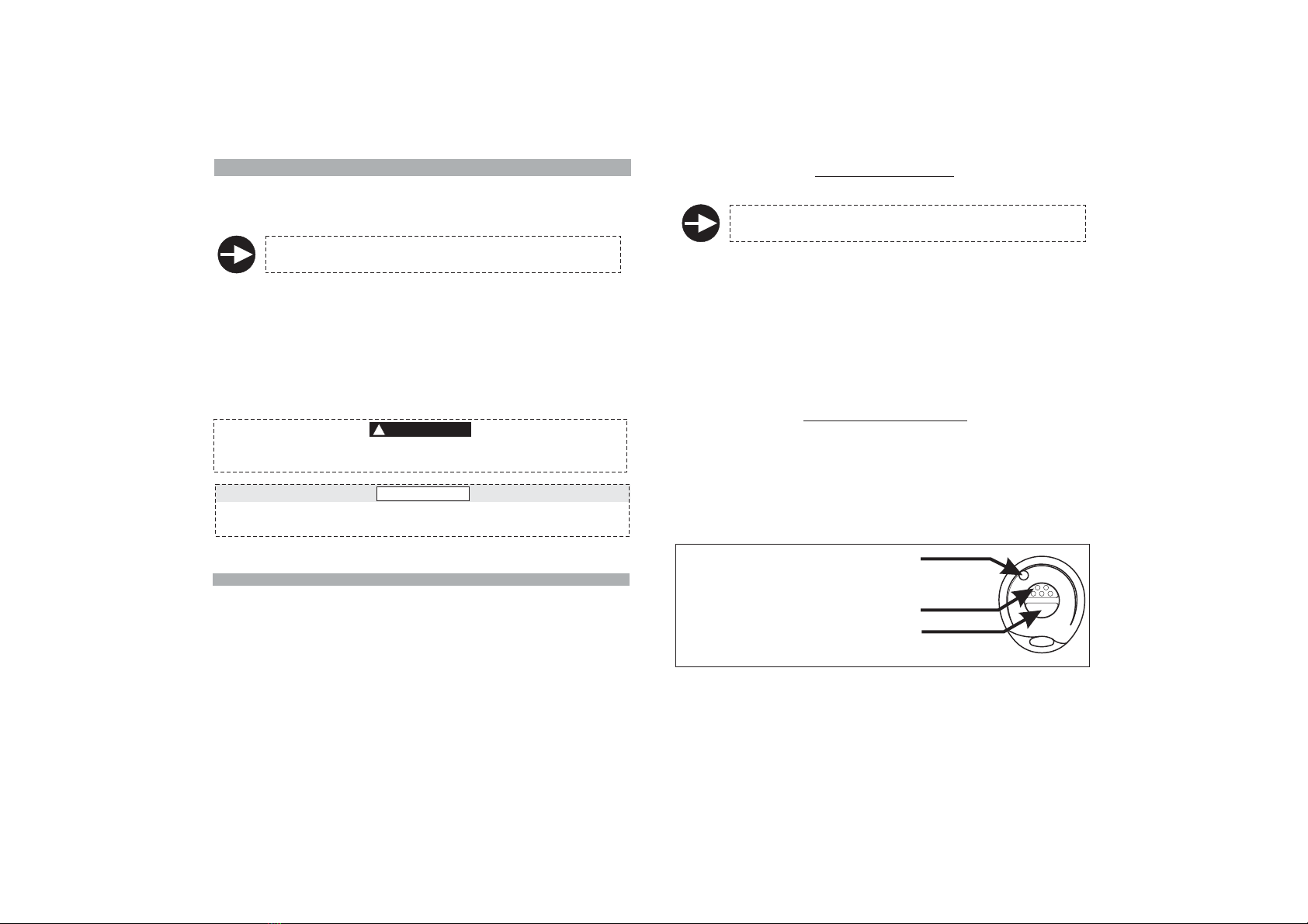
Press remote control button “1”.
Press the anti-hijack button (if available).
Walk away from your vehicle, it will activate automatically when the TAG is
no longer detected.
Press remote control button “2”.
The LED will turn ON steady and the turn indicators will flash twice to confirm
the anti-hijack feature has been activated.
20 sec. after the anti-hijack feature has been activated, the siren will sound for
approx. 1 min. while the turn indicators will flash until the anti-hijack is
deactivated.
The system will kill the engine 2 sec. after the siren is triggered.
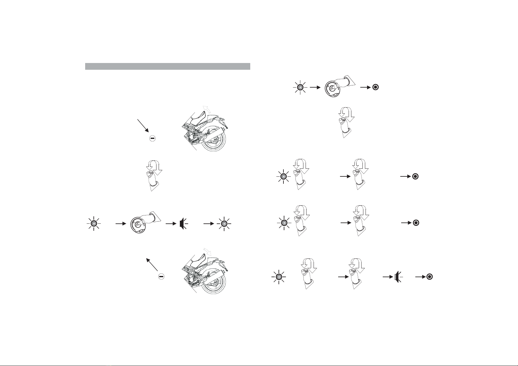
To exit the anti-hijack mode:
Press the TAG button.
Press the anti-hijack button for 2 sec. (if available).
Enter the PIN code.
To exit the anti-hijack mode via PIN code proceed as follows:
Wait for the siren to stop wailing.
If ignition key is in the ON position, turn it OFF.
If key is in the OFF position, cycle it ON and OFF.
After 4 sec. there will be a
From this point on, proceed as indicated in par. 7.0 and 8.0.
Disarming via PIN code will be confirmed by 3 Beep and 3 flashes of the
turn indicators.
!
!
!
!
!
!
!
!
!
sequence of 9 LED flashes.
4.7 - SELF-REARMING
When the system is armed and then accidentally disarmed, the system will
automatically rearm 35 sec. after it has been unintentionally disarmed.
4.6 - PRE-ALARM MODE
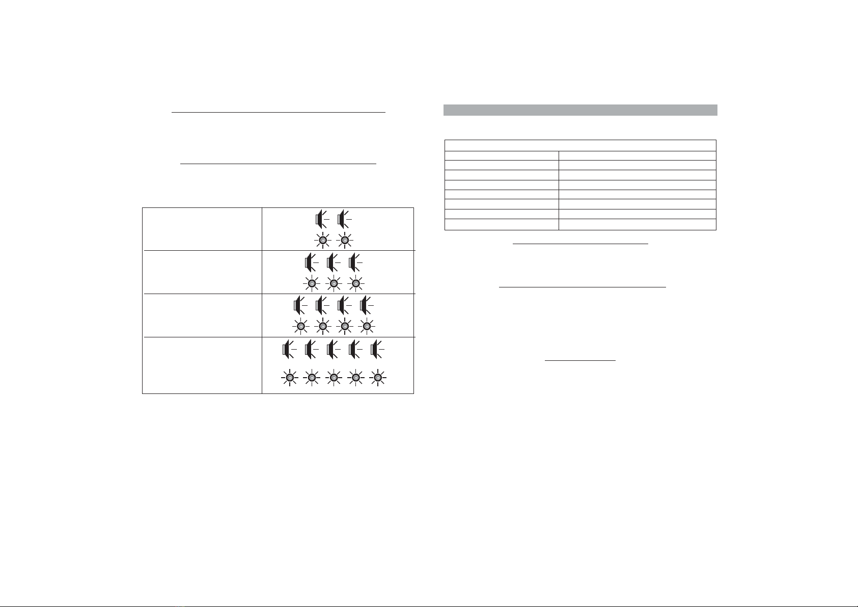
If the pre-alarm feature is enabled, the siren, during an alarm condition , will
start sounding for approx. 2.5 sec. for the first 3 cycles, then from the 4th cycle
on, it will sound for 30 sec.
Alarm cycles will be reset every time the alarm is disarmed or whenever the
panic alarm is activated.
PAGE 9 PAGE 10
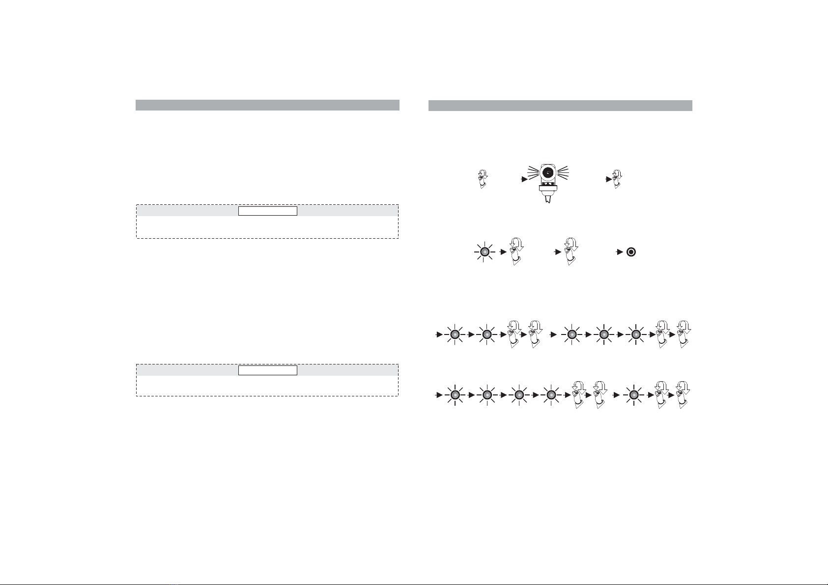
To activate the anti-hijack feature while the engine is running, either:
5.0 - SLEEP MODE - ENERGY SAVER FEATURE
6.0 - HAZARD WARNING FLASHERS
To make the turn indicators flash as Hazard warning lights, proceed as
follows:
With the system disarmed, turn ignition key in “ON”; the LED will light up for
approx. 1 sec.
While the LED is ON, press remote control button “1”.
Turn ignition key “OFF”; the turn indicators will start flashing.
To disable the flashers, turn ignition key “ON” (and eventually “OFF”) or
arm the system.
!
!
!
In order to preserve battery life, t
72h after it has been armed. All protection features are operative during
sleep mode except the status LED.
The remote control is inoperative, normal operation is restored when ignition
is switched ON.
If only the TAG is used, press the TAG button immediately after starting the
engine.
When the engine is switched ON, there is a 5 sec. delay to allow disarming
without triggering the siren.
he system automatically reverts to sleep
mode
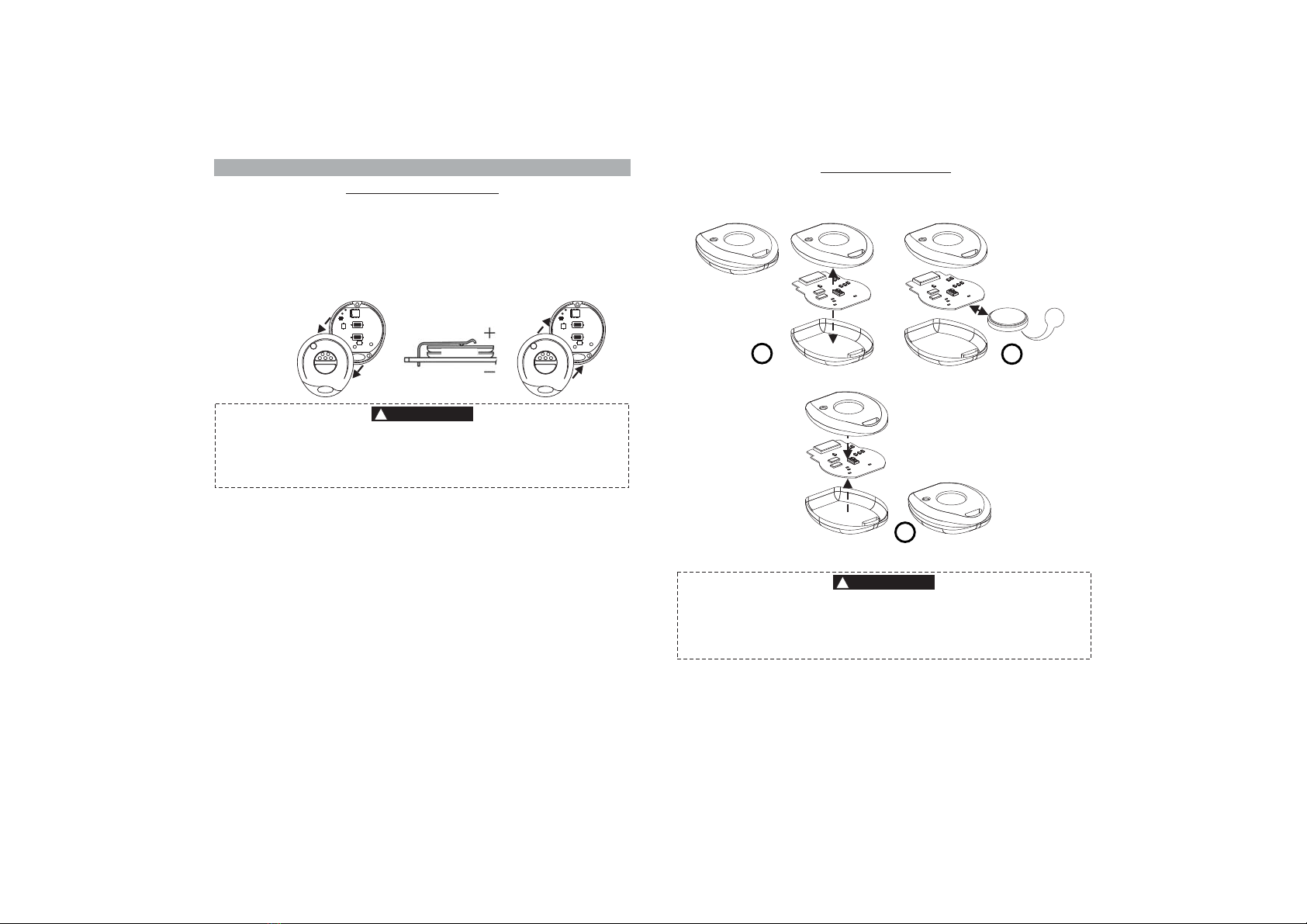
The anti-hijack mode has a memory feature.
I
it will be
considered a theft attempt.
f the power supply is disconnected and subsequently
reconnected an alarm will be triggered because

CAUTION
7.0 - PIN CODE OVERRIDE
If you cannot disarm the system from the remote control because it is lost or
broken or batteries are flat, you will be able to disarm the system by using the
PIN override procedure.
For security reasons, we recommend that you change the 4-digit PIN code
from the factory setting 1-1-1-1 (par. 9.0).
Trigger an alarm condition. After the warning signals, the status LED will
turn ON steady for approx. 5 sec.
To override the system:
While the LED is ON, cycle ignition key ON and then OFF
!
!.
If ignition key stays in the ON position for more than 5 sec., the system will
interpret the situation as a theft attempt and trigger another alarm.
!
!
!
!
The status LED will turn OFF to confirm the system is in override mode.
4 sec. after the LED has powered OFF, there will be a
.
Count the number of flashes and, at the number of flashes that equals the
PIN 1st digit, cycle ignition key ON and OFF to confirm the entered digit.
After 4 seconds, .
When the number of flashes equals that of the 2nd digit, cycle ignition key
ON and OFF to confirm the entered digit.
Repeat the above steps for the remaining two digits.
If the code has been entered correctly, the system will disarm and signal the
last cause of alarm (par. 3.9, “System disarming with alarm memory .
!
!
!
there will be another sequence of LED flashes
sequence of 9 LED
flashes
”)
If the LED blinks more than 9 times, the procedure will be invalidated and
considered a theft attempt.
CAUTION
PAGE 11 PAGE 12
8.0 - PIN CODE OVERRIDE EXAMPLE
To help you understand the override procedure by PIN code, here below is a
step-by-step example entering PIN code “2-3-4-1”.
After the alarm warnings are over, the status LED will turn ON steady for
approx. 5 sec. While the LED is ON, cycle ignition key ON and OFF; the
LED will go OFF to confirm the system is in PIN override mode.
After 4 sec. the LED will flash 9 times in sequence. Count the number of
flashes
equals that of the 1st digit .
After 4 sec., there will be another sequence of LED flashes. Cycle ignition
key ON and OFF after the 3rd blink (PIN code 2nd digit “3”).
and cycle ignition key ON and OFF when the number of flashes
(in this case “2”)
Arm the system. After the arming delay, trigger an alarm condition.
Repeat the above steps for the remaining two digits (” ).4” and “1”
Key “ON” Key “OFF”
Alarm condition
Key
“OFF”
Key
N“O ”
LED ON
approx. 5”
L OFF to
confirm
override mode
ED
First digit: “2” Second digit: “3”
“ON” “OFF”
4 Sec.
4 Sec.
4 Sec.
4 Sec.
Third digit: “4” Fourth
digit: “1”
If the PIN code has been entered correctly, the alarm system will disarm
and signal the last cause of alarm (see par. 3.9).
“ON”
“ON”“ON”
“OFF”
“OFF”“OFF”
If the LED blinks more than 9 times, the procedure will be invalidated and
considered a theft attempt.

9.0 - PIN CODE CUSTOMIZATION
Here below is a step-by-step example showing how to customize the factory
PIN code. In this case the selected PIN code is .2-3-4-1
Ground the BROWN-GREEN wire.
Disconnect the BROWN-GREEN
wire.
Open the seat (if protected by a
contact switch).
Close the seat if previously opened.
Turn ignition key “ON”.
The status LED will light up for approx.1 sec.
While the LED is ON, simultaneously press both remote control buttons.
2 Bops will sound and the LED will power ON steady.
D.isarm the alarm system
Key “ON”
1 sec. Bop
Bop
Steady
ON
GROUND
GROUND
BROWN-GREEN
BROWN-GREEN
PAGE 13 PAGE 14
Bop
Bop
Beep
Simultaneously press both
.
remote control buttons.
The LED will turn OFF
LED
OFF
LED
OFF
Turn ignition key “OFF”.
After 4 sec., the LED will flash 9 times in sequence.
Count the number of flashes and cycle ignition key ON and OFF when the
number of flashes equals that of the new PIN code 1st digit.
Repeat the above steps to enter the last 2 digits.
When the 4th digit is entered, the system automatically exits the procedure.
2 Bops and 1 Beep will confirm the code has been entered successfully.
After
.
4 sec., .
2nd digit
there will be another sequence of LED flashes
Repeat the above step to enter the
Key
“OFF”
Key
“ON”
Key
“ON”
Key
“OFF”
Key
“OFF”
Last
digit
LED
OFF
Key
“ON”
Key
“OFF”

10.0 - REPLACING
When the remote control batteries are too weak (see par. 2.2), replace them as
follows:
Separate the remote shells taking care not to damage the internal circuit.
Insert the new batteries taking care not to invert polarity.
Close the remote shells.
!
!
!
!
Remove the discharged batteries.
BATTERIES
10.1 - REMOTE CONTROL
Use only CR1616 batteries.
Discard used batteries properly in special dedicated containers.
Inserting the batteries the wrong way and/or using different type batteries
can damage the remote control or cause the batteries to explode.
BATTERIES
WARNING
!
PAGE15 PAGE 16
10.2 - TRANSPONDER
Proceed as follows to replace the battery:
1. Separate the plastic covers and remove the circuit with care.
3. Reassemble the
covers, turn ON
the TAG and make
sure it works.
1
3
+
2. Slide out the dead battery and
insert a new one. Pay attention
not to invert polarity.
2
Use only CR2032 type batteries.
Inserting the battery the wrong way and/or using different type batteries
can damage the remote control or cause the batteries to explode.
Discard used batteries properly in special dedicated containers.
ATTENTION
!

11.0 - WASTE ELECTRICAL AND ELECTRONIC EQUIPMENT
(WEEE) DIRECTIVE
The present device does not fall within the scope of Directive 2002/96/EC on
Waste Electrical and Electronic Equipment (WEEE) as specified in art. 2.1 of
Leg. Decree n. 151 of 25/07/2005.
12.0 - USE AND MAINTENANCE
:
Do not clean the alarm unit with water but use a damp cloth to wipe.
.
!
Care should be taken to protect the electronic alarm system
Do not use voltages other than the one specified by the manufacturer
Protect the alarm from any direct water flow such as high-powered water
jets found in a car wash.
!
!
Gemini Technologies will not be held responsible for any damage
caused by improper use.
ATTENTION
!
14.0 - WARRANTY CONDITIONS
n.206
6, 2005 (”Italian Consumer Sales Code”) and subsequent
amendments.
This product is guaranteed for 24 months from the date of purchase in
accordance with the provisions set forth in Leg. Decree dated
September
The product certificate, duly completed and accompanied by the original sales
receipt will constitute proof of purchase.
The warranty shall be void if labels on the product or on the certificate are
missing or torn, if the certificate is not fully completed or if the enclosed sales
receipt is missing.
The manufacturer is responsible for any aspect of installation, after-sales
service and/or technical support and, should these services be included in the
sales contract, they will be the exclusive responsibility of the retailer.
Consumers who need to enforce their statutory consumer guarantee rights
against defective products - in accordance with Art. 128 et seq. of the Italian
Consumer Sales Code (Leg. Decree n.206 as above)- must personally contact
the retailer.
The manufacturer declines any responsibility for eventual malfunctions or
failures of the product and/or any damage whatsoever caused by improper
installation, use or tampering.
This alarm system is solely intended to be a theft-deterrent device.
NOT
Power supply
Power supply range
Current absorption @ 12Vdc
Relay capacity
Current absorption in
Siren sound level
sleep mode
12 Vdc
9Vdc-15Vdc
)
mA
118dBA @1m
8A
< (system armed and LED
flashing
<1
2mA
13.0 - TECHNICAL SPECIFICATIONS
PAGE 17 PAGE 18
Turn indicator output
Gemini Technologies will not be held responsible for any damage
caused by improper use.
12V max. (6A max. per side)

INSTALLER MANUAL
15.0 - FITTING INSTRUCTIONS
Please read all instructions and understand them thoroughly before starting
the installation.
The present manual is to be considered an integral part of the alarm
system.
17.0 - ALARM UNIT POSITIONING
Do not install the alarm unit in this
position as water ingress over time
may seep through the rubber sheath
and permanently damage the
electronic circuit making the alarm
unreliable.
Eventual malfunctioning due to water
infiltration is not covered by warranty.
!
!
!
Fitting the alarm in this position will prevent water
entering the unit.
It is important to give the rubber sheath a “
bending as shown in the picture opposite and
secure with a tie wrap.
Do not expose to atmospheric agents.
goose-
neck”
!
!
!
!
!
Pay attention not to muffle the siren speaker.
Secure away from moving mechanical parts.
Keep away from devices that could reach high
temperatures when the vehicle is in use.
Do not secure the alarm unit directly on the vehicle
frame.
Keep away from devices that could generate high
frequency electromagnetic disturbances.
NO!
OK!
Since the alarm system has a built-in high sensitivity triaxial tilt sensor, it can
be positioned either vertically or horizontally as long as you keep the following
:in mind
PAGE19 PAGE 20
Do not jet wash the alarm unit.
The warranty will not cover damages to the alarm system due to water
ingress caused by improper installation or jet washing.
ATTENTION
!
16.0 - ALARM UNIT SEALING
To seal the alarm, position the
rubber cap over the external edge of
the alarm housing as shown below.
Pull the plastic rectangular flange
over the rubber cap and secure with
the supplied screws.
Do not over tighten the screws.
Alarm unit sealed

18.0 - ACCESSORIES
18.1 - STATUS LED
Since the LED warning light serves as both a system status indicator and a
visual deterrent it
Always check the rear clearance before drilling:
• Drill a
must be installed where it can readily be seen.
ø 10mm hole and insert the LED holder.
• Gently press the LED holder until it clicks into place.
• Connect the LED Black 2-pin connector to the alarm Black 2-pin connector.
• Bundle up and tie down any excess wires.
18.2 - CONTACT SWITCH (OPTIONAL)
A contact switch can be fitted to protect the seat or topcase. It must be installed
in such a way as to detect the opening of the seat/topcase without being
accessible from the outside.
An alarm will
NB:
be triggered when negative
signal.
the GREEN/BROWN wire detects a
If no contact switch is fitted, the GREEN/BROWN wire will remain free for
other possible uses such as programming the alarm or learning new devices.
PAGE 21 PAGE 22
Attach to cut end of key switch wire
Attach to cut end of main wiring harness.
.
Connect to a permanent negative connection
(do not connect to vehicle chassis
Connect to the cable end which, if grounded, will kill
the engine.
).
19.0 - PINOUT TABLE
Wire functionWire colorPos.
-1-
-2-
-3-
-4-
-5-
-6-
-7-
-8-
-9-
-10-
-11-
-12-
-13-
-14-
-15-
-16-
---
Brown
White-Violet
Green-Brown
---
---
Yellow
Black
---
Grey
White
White-Grey
Orange
Red
Orange
Black
N/A
Power supply earth ground
Turn indicators (12V, 6A max.)
Positive supply
Turn indicators (12V, 6A max.)
LEARN button / Anti-hijack
N/A
N/A
Ignition
LED
N/A
Contact switch input
Immobilizer (N.C.)
Immobilizer (Com.)
Immobilizer (N.O.)
Antenna
negative output
IMMOBILIZER - wire joint
IMMOBILIZER - grounded wire
Wire color
Wire color
White
Grey
White
White/Grey
Connections
Connections
CAUTION
Alarms are supplied without wiring harnesses. A wide range of specific pin-
to-pin wiring harnesses is available for the most common motorbikes.
KITCA 417N17.The following tables refer to the generic wiring harness
18.3 - ANTI-HIJACK BUTTON (OPTIONAL)
Connect the anti-hijack button to the White-Violet wire. The anti-hijack will
trigger when a negative signal is detected.
ATTENTION
!
This alarm system is intended for 12V turn indicators.
sure the flashers are powered by a
12V signal.
Before you do any electrical work, make

Turn indicators
(12V)
Optional fuse
(recommended)
Key
switch
White-Grey
White
Grey
10A Red
Ground
Battery
12 V
Brown
Yellow
Green-Brown
Immobilizer
White-Violet
16
8
12
4
14
6
10
2
15
7
11
3
13
5
9
1
20.0 - WIRING DIAGRAM
Orange
Orange
Seat/topcase
contact switch
(recommended)
PAGE 23 PAGE 24
Status
LED
21.0 - IMMOBILIZER CONNECTIONS
Key switch
White
Immobilizer wire
Cut
Grey
To vehicle engline
Key switch
White
Immobilizer wire
Ground
White/Grey
To vehicle engine
ENGINE IMMOBILIZER - GROUNDED WIRE
For most small
2-stroke motorcycle engines.
ENGINE IMMOBILIZER - CUT WIRE

PAGE 25 PAGE 26
22.0 - DIODE INSTALLATION
Activate one of the turn indicators, turn ignition key OFF and arm the alarm.
If the instrument panel lights up when the turn indicators are activated, a
diode needs to be installed (follow diagram below).
!
How to tell if you need to install a diode:
!
Vehicle wiring harness
After
Turn indicator
relay
WHITE wire
Cut
Diode installed
in-line
Vehicle original
wire
Live feed to
turn indicators
BLACK wire
Before
CAUTION
23.0 - LEARNING NEW DEVICES
The alarm system is supplied with 1 active remote control and 1 TAG that must
be activated.
To pair the TAG and learn new devices, follow one of the 2 procedures:
Alarm memory will only store 8 devices.
Saving an extra device will automatically delete the first one.
23.1 - BY GROUNDING THE BROWN/GREEN WIRE:
!
!
Disarm the alarm system via remote control.
Lift the seat or open the topcase (if fitted with a contact switch) otherwise
ground the BROWN/GREEN wire.
!Ground the White-Violet wire (with or without a Yellow end connector).
!
!
!
!
!
Turn ignition key in ON.
Press the TAG button or one of the buttons on the remote control to be
learned.
A flash of the turn indicators and a Beep will confirm the new remote has
been learned.
If other devices need to be learned, then press
the button on the device to be learned.
To exit the learn procedure, turn ignition key OFF. A Bop and a single flash
of the turn indicators will confirm the end of the procedure.
Close the seat/topcase or remove the BROWN/GREEN wire from
ground.
!
!
!
Disconnect the White-Violet wire.
repeat the above procedure
2 flashes of the turn indicators and 2 confirmation tones (1 Bop and 1 Beep)
will acknowledge the system is in learn mode.
23.2 - WITHOUT GROUNDING THE BROWN/GREEN WIRE:
!
!
!
Disarm the alarm system via remote control.
Turn ignition key in ON.
.
If other devices need to be learned, wait 2 sec. and then press the button on
the device to be learned.
To exit the learn procedure, turn ignition key OFF.
!
!
The status LED will light up for 1 sec.; while the LED is ON, simultaneously
press both buttons on the active remote control.
2 flashes of the turn indicators and 2 confirmation tones (1Bop and 1 Beep)
will acknowledge the system is in learn mode.
!
!
!
Press the TAG button or one of the buttons on the remote control to be
learned
A Bop and a single flash of the turn indicators will confirm the end of the
procedure.

PAGE 28
After pressing both buttons simultaneously (step 4), program the features
according to your needs.
EXIT PROGRAMMING
24.0 - PROGRAMMABLE FEATURES
To either enable or disable one of the programmable features, proceed as
follows:
NB: Remember to ALWAYS arm/disarm the system before programming.
4
2
3
With the system disarmed, lift the seat
or open the topcase (if protected by a
contact switch) otherwise ground the
GREEN/BROWN wire.
NB: Remove the wire from ground after
programming.
Turn ignition key in ON.
The status LED will light up for approx. 1 sec.
While the LED is ON, simultaneously press
both remote control buttons.
Two confirmation tones (1 Bop and 1 Beep)
will acknowledge the system is in
programming mode.
The LED will light up steady.
1
Button ENABLE
Button DISABLE
1:
2:
Button 1: ENABLE
2: DISABLEButton
Button ENABLE
Button DISABLE
1:
2:
Button ENABLE
Button DISABLE
1:
2:
Button ENABLE
Button DISABLE
1:
2:
Button ENABLE
Button DISABLE
1:
2:
Button ENABLE
Button DISABLE
1:
2:
PANIC
()
ALARM
factory enabled
ACOUSTIC SIGNALS
(factory enabled)
TILT SENSOR
(factory enabled)
SYSTEM SELF-REARMING
()factory disabled
PASSIVE ARMING
()factory enabled
ANTI-HIJACK
()factory enabled
PRE-ALARM
()factory disabled
TO ENABLE TO DISABLE
Press button 1Press button 2
PAGE 27
Beep Bop

CAUTION
25.0 - PROGRAMMING EXAMPLE
Here below is a step-by-step example showing how to program the system
with the tilt sensor and self-rearming disabled.
.
Keep in mind that, at every button press, the system automatically scrolls to the
next feature.
With the system disarmed, lift the seat/topcase (if protected by a contact
switch) otherwise ground the BROWN/GREEN wire.
Turn ignition key in ON; the LED will light up for approx. 1 sec.
While the LED is ON, simultaneously press both remote control buttons; 2
Beeps will confirm the system is in programming mode and the LED will
light up steady.
Press remote control button 1; a Beep will confirm acoustic signals are
enabled.
; a Beep will confirm that the panic alarm is
enabled.
Press button 1; a Beep will confirm that passive arming is enabled.
Press button 1; a Beep will confirm that the anti-hijack feature is enabled.
Press button 1; a Beep will confirm that the pre-alarm feature is enabled.
Press button 2; a Bop will confirm that is disabled.
When the last feature has been configured, the system automatically exits
the programming procedure; 2 Bops and 1 Beep will confirm the end of the
procedure. The status LED will power OFF.
Turn ignition key OFF, close the seat/topcase or remove the BROWN-
GREEN wire from ground.
!
!
!
!
!
self-rearming
!
!
!
!
!
!
Press remote control button 1
Press button 2; a Bop will confirm that the is disabled.tilt sensor
You can exit the programming procedure at any time by turning ignition
key OFF.
Programmed features will automatically be saved while the others will
remain unvaried.
PAGE 29
26.0 - TILT SENSOR ADJUSTMENT
The alarm system has a built-in triaxial tilt/shock sensor with 4 levels of
sensitivity adjustment. T e shock sensor is factory preset to be at minimum
sensitivity.
To change the sensitivity level proceed as follows:
Disarm the alarm system via
Lift the seat/topcase (if protected by a contact switch) otherwise ground the
BROWN/GREEN wire.
.
!
!
!
h
remote control.
Turn ignition key ON; the status LED will turn ON for approx. 1 sec
!While the LED is ON, press remote control button 2 and press it again within 2 sec.
CAUTION
The procedure will be voided if more than 2 seconds go by between the
first button press and the second.
!
!
Two LED flashes and two Beeps will confirm the system is in adjustment
mode.
Sensor is at the lowest sensitivity level.
!
!
!
!
Press remote control button 2 to increase sensitivity by one (press 3 times
to set at maximum level); a LED flash and a Beep will confirm each change
of setting.
When the sensor is adjusted, turn ignition key OFF.
If adjusted at the highest level (3 button presses), the system automatically
exits the procedure.
In both cases, a LED flash and Beep will confirm the end of the procedure.
!
.
Turn ignition key OFF. Close the topcase/seat or remove the
BROWN/GREEN wire from ground
CAUTION
Every time you enter the programming procedure, sensitivity is restored to
the factory default setting.
PAGE 30

Company
Address, City
Country
Phone number
Fax number
Art. of Directive
3.1 (a) Health
3.1 (a) Safety
3.1 (b) EMC
3.1 (b) EMC
Art. of Directive
3.2 Spectrum
Product description:
Intended use:
EU / EFTA member states intended
for use
Member states with restrictive use
Manufacturer
Brand name
Type / Model
GEMINI TECHNOLOGIES S.r.l
Via Luigi Galvani 12, 21020 Bodio Lomnago (VA)
Italy
+39 0332 943211
+39 0332 948080
Standard
EN 50371
EN 60950-1 +A11
EN 301 489-3
E 301 489-1
N
Standard
EN300 220-2
TCF reference n°
Date
Name and position
Date of issue
2002
2006; 2009
V2.1.1 (2009-05)
V1.8.1 (2008-04)
Date of issue
V2.3.1 (2010-02)
TCF_ 7208E/7218E
August 23, 2010
Andrea Rossi, Managing Director
Remote control at 433,92 Mhz
For vehicle alarm systems
EU: all members
EFTA: all members
None
GEMINI TECHNOLOGIES S.r.l.
GEMINI
7208E and 7218E
We, the undersigned,
R&TTE Declaration of Conformity
Doc ref. No. 2010-01
Declare under our sole responsibility that the following equipment:
Is tested to and conforms with the essential requirements of Art. 3.1 (a) for protection of
Health and Safety of the user and any other person and of Art. 3.1 (b) for Electromagnetic
Compatibility, as included in the following standards:
And is tested to and conforms to Art. 3.2, with the essential radio test suites so that it
effectively uses the frequency spectrum allocated to terrestrial/space radio
communication and orbital resources so as to avoid harmful interference, as included in
the following standards:
And therefore complies with the essential requirements and provisions of
of the European Parliament and of the Council of March 9, 1999 on radio
equipment and telecommunications terminal equipment and the mutual recognition of
their conformity and with the provisions ofAnnex II.
Directive
199/5/EC
NOTES
Table of contents
Other Gemini Motorcycle Accessories manuals
Popular Motorcycle Accessories manuals by other brands

Memphis Shades
Memphis Shades 2321-0036 Mounting instructions

Conrad
Conrad 2564529 operating instructions

BoxerCafe
BoxerCafe Battery Relocation Kit instruction sheet

BEROTEC
BEROTEC CUMPAN FANTIC Caballero 125 user guide

SW-Motech
SW-Motech GPT.07.904.65100/B Mounting instructions

Cardo Systems
Cardo Systems scala rider Q3 quick guide