PRELIMINARY ADVICE
Please read all instructions and understand them thoroughly before
starting installation.
1.0 - PRELIMINARY ADVICE..........................................................
2.0 - ALARM POSITIONING............................................................
3.0 - ACCESSORIES POSITIONING..............................................
3.2 - Contact switch (optional).......................................................
4.0 - ALARM UNIT SEALING..........................................................
6.0 - ELECTRICAL CONNECTIONS...............................................
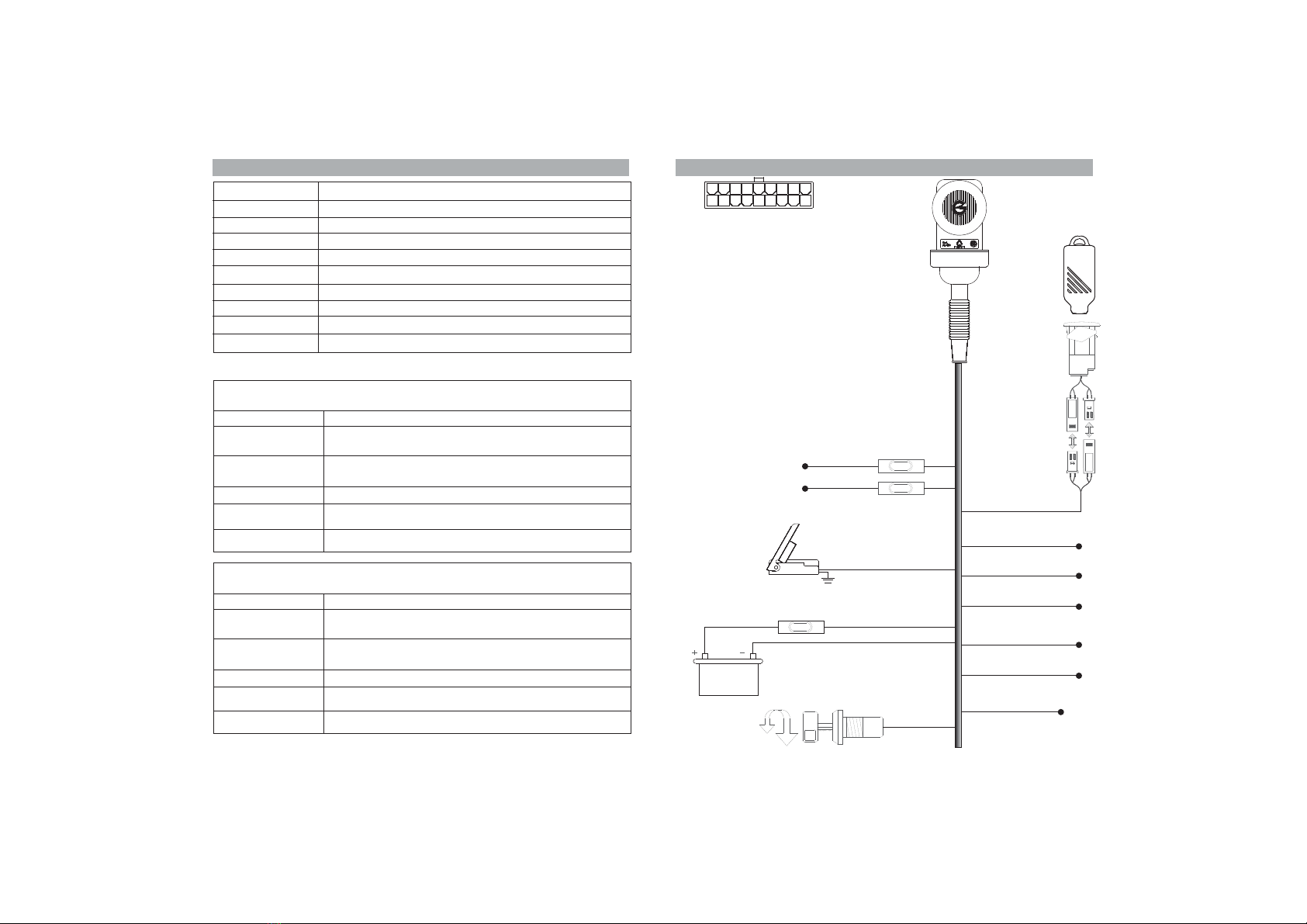
7.0 - WIRING DIAGRAM AND PINOUT...........................................
8.0 - DOUBLE ENGINE IMMOBILIZATION......................................
8.1- Electronic ignition....................................................................
8.2- Grounded wire.........................................................................
9.0 - PAIRING NEW DEVICES.........................................................
9.1 - With Brown/Green wire connection.........................................
9.2 - Without Brown/Green wire connection....................................
10.0 - PROGRAMMABLE FEATURES.............................................
11.0 - PROGRAMMING EXAMPLE.................................................
12.0 - REMOTE CONTROL.............................................................
13.0 - WASTE ELECTRICALAND ELECTRONIC EQUIPMENT.......
14.0 - TECHNICAL SPECIFICATIONS.............................................
3.1 - Electronic key receptacle......................................................
5.0 - ALARM POSITIONING FOR MAXIMUM SENSITIVITY..........
PAGE 02
PAGE 03
PAGE 04
PAGE 0
PAGE 0
PAGE 0
PAGE 06
PAGE 08
PAGE 09
4
4
5
PAGE 10
PAGE 10
PAGE 11
PAGE 12
PAGE 12
PAGE 13
PAGE 14
PAGE 15
PAGE 16
PAGE 17
PAGE 17
PAGE 2 PAGE 3
WARNING
!
CAUTION
NOTE
Non-compliance to this instruction could result in serious damage to the alarm
system and the vehicle itself.
Non-compliance to this instruction may cause serious damage or operational
failures to the alarm system.
Provides useful installation tips.
The following signal words are used throughout this manual to emphasize
important instructions or special information.
2.0 - ALARM POSITIONING
!
!
!
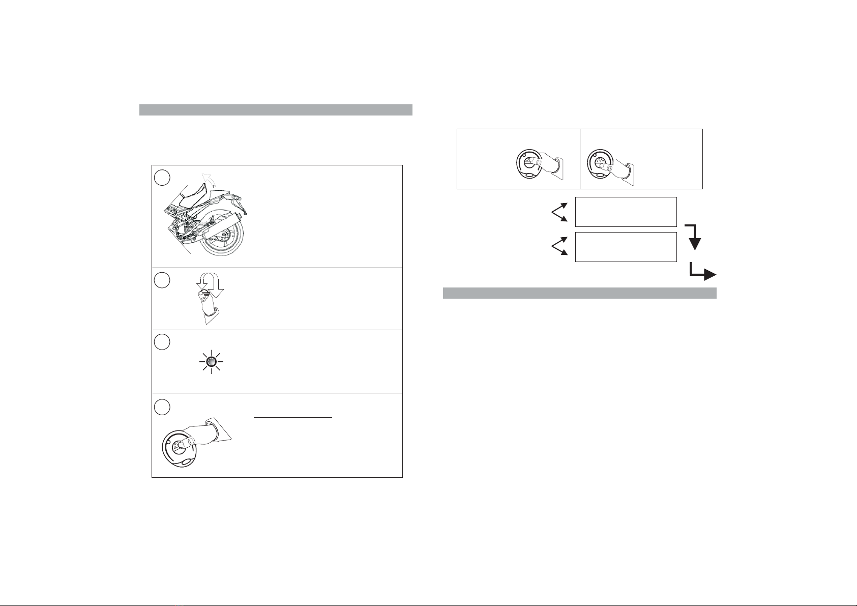
Fit th alarm as shown in the picture opposite to
prevent water entering the unit
Give the a ‘goose-neck’ bending as
shown and secure with a tie wrap.
.
e
.
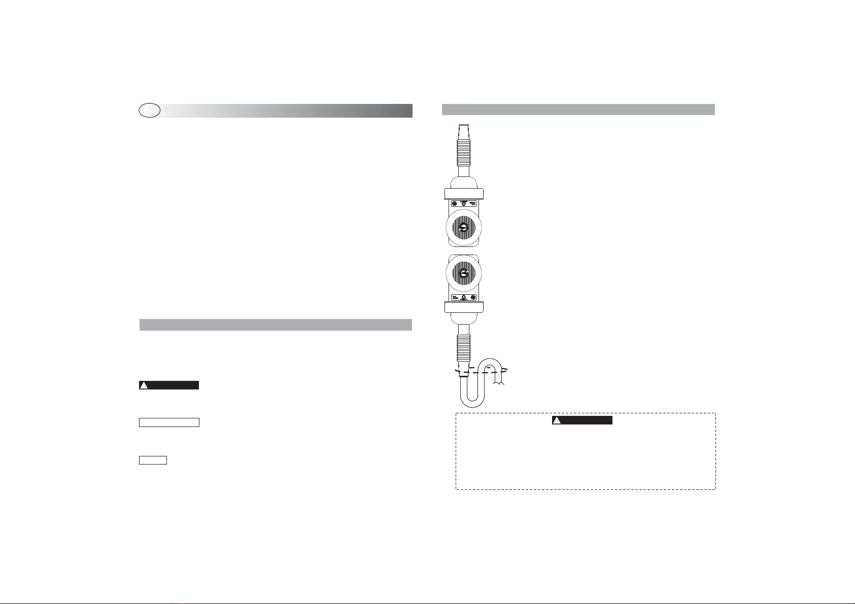
Do not install the!
rubber sheath
The alarm unit must be installed in such a way as
not to muffle the siren but it must not be exposed to
atmospheric agents
Install the alarm away from moving mechanical
parts, electric or electronic components that could
generate high frequency electromagnetic
disturbances and away from devices that could
reach high temperatures when the vehicle is in use.
alarm unit directly on the vehicle
frame.
!
Do not install the alarm unit in this
position as water ingress over time
may seep through the rubber
sheath and permanently damage
the electronic circuit making the
alarm system unreliable.
Eventual malfunctioning due to
water infiltration is not covered by
warranty.
NO!
OK!
UK CONTENTS
WARNING
!
If a jet wash is used to clean the vehicle, protect the alarm unit from
water splashes and be careful not to expose it to high pressure jets.
The warranty will not cover damages to the system due to water
infiltrations caused by improper installation, improper jet washing or
the use of non original accessories, not approved by the
manufacturer.