Gemini gtrack 7855 MyBASIC User manual

UK
7855
MyBASIC
USER MANUAL
AC 2697/UK - REV.08 - 05/15
Made in Italy

1.0 - TABLE OF CONTENTS
1.0
2.0
3.0
4.0
5.0
6.0
7.0
11.0
- TABLE OF CONTENTS
- INTRODUCTION
- CONTROL DEVICES
- ARMING
- DISARMING
- OPTIC SIGNALS
Arming/disarming signals
Pre-alarm signals
- PRE-ALARM AND ALARM
alarm
Tilt alarm
Position alarm
Battery alarm
COMMANDS FROM AND TO MOBILE PHONE
VEHICLE PARKING
- MESSA
3.1 - Remote control
3.2 - Electronic key
6.1 -
6.2 -
- ALARMS
8.1 - Ignition detection
8.2 -
8.3 -
8.4 -
8.5 - Generic alarm (GREEN-BROWN wire)
8.6 - Wireless sensors alarm
-
9.1 - Initial configuration
9.2 - STOP & GO activation
9.3 - STOP & GO deactivation
9.4 - Tilt sensor exclusion
9.5 - Vehicle localization
9.6 - Tracking (vehicle movement)
9.7 - Speed control
9.8 - Engine immobilizer activation
9.9 - Engine immobilizer disabling
9.10 - Blinker activation
9.11 - System arming
9.12 - System disarming
9.13 - System status
9.14 - System passive arming
9. Periodic vehicle position control setting
Auxiliary input configuration
-
GES
11.1 - Error messages
11.2 - Alarm messages
8.0
9.0
10.0
15 -
9.16 -
UK

2.0 - INTRODUCTION
Dear Customer, thank you for choosing this self-managed tracking system,
designed and manufactured in Italy by GEMINI TECHNOLOGIES specifically
for 2-wheeled vehicles. Being highly flexible it can also be used to protect
Please read the present manual carefully
to make sure you always have
enough credit
ATVs
and heavy-duty machinery.
is only applicable to devices labeled Rev.08 or
higher.
Google Maps link
to fully take advantage of all the
security features offered by the system without triggering false alarms that can
use up needlessly your SIM credit. If the MyGTRACK is set up with a prepaid
SIM card, periodically check on your balance
.
TheNB:
The following signal words are used throughout this manual to emphasize
important instructions or special information. Do keep this manual handy for
future reference.
12.0
13.0
14.0
15.0
- MyGTRACK MANAGEMENT EXAMPLE
12.1 - System configuration
12.2 - Vehicle localization
- VEHICLE MAINTENANCE
- REMOTE CONTROL BATTERY REPLACEMENT
-
CONTROL UNIT MAINTENANCE
COMMANDS
-
- WASTE ELECTRICAL AND ELECTRONIC EQUIPMENT (WEEE)
16.0
17.0
WARNING
!
Non-compliance to this instruction could result in serious damage to the
GPS alarm system and the vehicle itself.
Non-compliance to this instruction may cause serious damage or
operational failures to the GPS alarm system.
ATTENTION

KEEP YOUR PASSWORD STORED INASAFE PLACE
ALWAYS CARRY YOUR remote control and electronic key but NEVER
together with the vehicle keys
f the system is armed and all override devices have been lost, the engine can
only be started by first disarming the system
.
.
I
(see command table).
Electronic key
3.2 - ELECTRONIC KEY
The electronic key is a simplified remote control. In emergency situations (ex.
in case of remote control failure), it can be used to arm/disarm the tracking
system.To use the electronic key, simply touch it to its receptacle.
The receptacle incorporates a LED warning light that serves as both a system
status indicator and a visual theft deterrent.
3.0 -
3.1-R
CONTROL DEVICES
EMOTE CONTROL
The remote control has a low charge battery indicator that gives you early
warning to avoid malfunctioning. When the batteries are fully charged, the LED
will show a steady light at the press of a button. If the batteries are too weak for
normal operation, the LED will start blinking at the press of a button.
The remote control is the main interface with the tracking system; we therefore
recommend you acquaint yourself fully with it.
Arming and
disarming
button
LED
indicator
E
.
xample of
receptacle
positioning on the
vehicle plastic
fairing
ATTENTION

4.0 - ARMING
To arm the system press once on the remote control button or touch the
electronic key to its receptacle.
The LED and the turn indicators will blink twice to confirm arming.
5.0 - DISARMING
To disarm the system press once on the remote control button or insert the
electronic key in its receptacle.
The LED and the turn indicators will blink 3 times to confirm disarming; the
vehicle can then be started.
To restore passive arming, turn ignition key “ON” and then “OFF”.
While the system is armed and, until it is disarmed, the vehicle cannot be started.
The passive arming feature, enabled via SMS (see chapter 9.14 or 15.0),
automatically arms the system 2 minutes after ignition is switched “OFF”.
To exclude auto-arming proceed as follows:
Turn ignition key “ON” and wait for the LED to light up.
Within 10” from LED ignition, insert the electronic key in its receptacle.
Passive arming exclusion is confirmed by 4 optical signals.
Turn ignition key “OFF”.
!
!
!
!
With the electronic key, the system arms immediately but there is a 60”
delay period within which no alarm is detected.
ATTENTION
ATTENTION
Passive arming exclusion is bound to a single arming cycle.

Arming
Disarming
BASIC
BASIC
LED flashes
LED flashes
(15”)
Turn indicator flashes
Turn indicator
flashes (15”)
6.0 - OPTICAL SIGNALS
6.1 - ARMING/DISARMING SIGNALS
6.2 - PRE-ALARM SIGNALS
NB: see installer manual (chap. 3.0) for the complete list of optical signals.

8.0 - ALARMS
8.1 - IGNITION DETECTION ALARM
8.2 - TILT ALARM
8.3 - POSITION ALARM
8.4 - BATTERY ALARM
This alarm is triggered if ignition key is turned “ON” while the system is armed
15.0.
The system
().
.
The
.
When the system is armed, attempts to lift or move the vehicle (including hauling or
wheel stealing) will trigger an alarm. To exclude this alarm see chapter 9.4 or
provides protection against displacement attempts while ignition
is OFF ex. towing
When ignition is switched back “ON”, the system compares the actual position
to the position saved when the engine was powered off.
If they differ by more than the factory set tolerance (not modifiable), the system
sends the user an alarm message
system rovides protection against battery tampering. If one of the power
supply cables is cut, the system sends an alarm message to the user (no pre-
alarm signal is triggered).
p
7.0 - PRE-ALARM AND ALARM
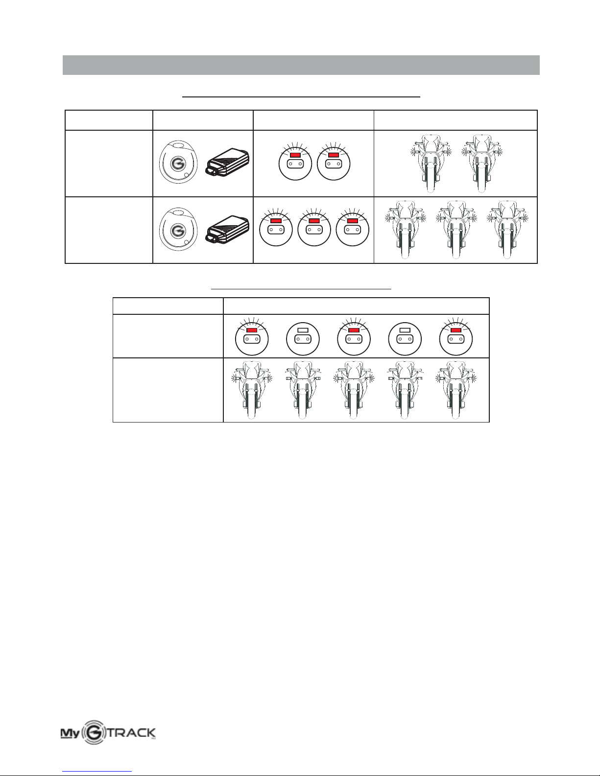
When the My GTRACK is armed, there is a pre-alarm and an alarm stage.
Pre-alarm is signalled by 15” of optical signals (LED and indicator lights) during
which the system can be disarmed via remote control. If the system is not
disarmed, an alarm is triggered and an alert message transmitted to the “main
number” indicating the type of alarm (ignition alarm, tilt alarm, etc.).
If no one intervenes within 5 minutes, the system sends a 2nd text message to
the emergency number (see chapter “Commands from/to a mobile phone”).
Ignition remains inhibited.
ATTENTION
Whenever an alarm message is sent, the system triggers the siren and
the turn indicators (if connected).

8.5 - )GENERIC ALARM (GREEN-BROWN wire
When a generic message is sent, the system checks the alarm source. If the
alarm source is still active (i.e. seat still open), the input will be inhibited. If no
longer active (i.e. seat closed), the system will automatically rearm
.
.
8.6 - WIRELESS SENSORS ALARM
Wireless sensors can be added to protect the area where the vehicle is usually
parked; if one of the sensors detects an alarm condition, an alert message will
be sent to the user mobile phone
ATTENTION
A generic alarm message will only be transmitted if the installer has
connected and programmed the system accordingly.
ATTENTION
ATTENTION
The code for requesting speed alert and vehicle position must always be a
3-digit number (factory pre as “000”, three zeros).set
If a text message is sent with the wrong command, you will receive an
error message (command error).
9.0 - COMMANDS FROM AND TO MOBILE PHONE
Before configuring the module, it is important to familiarize yourself with all the
commands available to interact with the system.
Messages for system management (commands) are forwarded to the same
mobile from which they have been transmitted (except tracking and vehicle
immobilizing confirmation).
Alarm messages are received by the preset mobile numbers.
NB: the time indicated by the system refers to the Greenwich Mean Time (GMT).

ATTENTION
9.1 - INITIAL CONFIGURATION:
setup#password#version#main phone number#new
password#emergency phone number#
The initial configuration command must be sent to the control unit to notify the
“password”, “system model” and “phone number” for the alert notifications:
configuration command.
factory preset password “000000”, six zeros.
- setup#:
- password#:
The new password
Commands
must be a 6-digit code and can contain both numbers
and letters (i.e.: AA1234 or aa1234). The password is key-sensitive,
therefore by typing characters other than the ones entered ( and
letters are not equivalent), the system will not operate properly.
can either be sent with capital or small letters.
upper
lower case
-Version#:
-Main phone number#:
-New password#:
-Emergency phone number#:
setup ok with password=new password.
system model (in this case BASIC).
number to which the SMS will be sent in case of an
alarm condition (i.e. +44 for the UK).
user-chosen password (6 digit-code mandatory).
second recipient to receive an SMS in case
of an alarm condition (optional, entering can be omitted).
To confirm reception of an SMS, the system triggers 5 quick flashes of the turn
indicators and the LED and returns a confirmation message to the user
indicating:
always preceded by the international code

9.2 - STOP & GO ACTIVATION:
9.3 - STOP & GO DEACTIVATION:
9.4 - :
setup#password#basic#main phone number#new
password#emergency phone number#f#
setup#password#basic#main phone number#new
password#emergency phone number#s#
setup#password#nav#main phone number#new
password#emergency phone number#
Upon reception of SMS, the system replies:
Every time ignition key is turned “ON”, the user will receive this message:
Every time ignition key is turned “OFF”, the user will receive this message:
When the SMS is received, the system replies:
By sending this command, the user will no longer receive a message every
time ignition key is turned “ON” or “OFF”.
When the SMS is received, the system replies:
The system will ignore any alarm triggered by a displacement attempt. To re-enable
the tilt sensor send the initial configuration message (see chapter 9.1).
setup ok with password= new password.
Key On GPS status; latitude; longitude; speed; hour; date.
Key Off, GPS status; latitude; longitude; speed; hour; date.
Setup ok with password= new password.
TILT SENSOR EXCLUSION
ATTENTION
The system can be configured with the “STOP & GO” feature (SMS alert
every time ignition is turned ON or OFF (see chapter 9.2, 9.3 or 15.0) and
the tilt sensor can be excluded (see chapter 9.4 and 15.0).
9.5 - VEHICLE LOCALIZATION:
loc#password#
Upon request, the system sends an SMS indicating:
System status (armed or disarmed), GPS status; latitude; longitude;
speed; hour; date.

9.6 - TRACKING
(VEHICLE DISPLACEMENT):
trk#password#
Upon request, the system sends 6 SMS (1 approx. every 90 seconds, the first
one to the sender and the other 5 to the user), indicating:
GPS status; latitude; longitude; speed; hour; date.
9.7 - SPEED CONTROL:
speed#password#060
The last 3 digits “060” stand for the speed expressed in km/h. If this speed is
exceeded for more than 20”, the system sends the user (after 20”) a speed
alert SMS (indicating vehicle position, time, date, etc). When the engine is
switched “OFF”, a second SMS will be sent with the top speed reached.
If the maximum speed is exceeded for less than 20”, the system will send a
“maximum speed exceeded” message when the engine is turned off.
To avoid receiving this message, set speed value as “000” (three zeros).
9.8 - ENGINE IMMOBILIZER ACTIVATION:
9.9 - ENGINE IMMOBILIZER DISABLING:
stop#password#
go#password#
At this request, the sender will receive a confirmation message.
When the engine is cut-off (vehicle stopped with GPS speed zero), the system
will send the user an SMS indicating engine stop and vehicle position (latitude;
longitude; speed; hour; date).
When the engine immobilizer is disabled, the system sends an SMS to the user
to confirm operation.
ATTENTION
The engine immobilizer can ONLY be disabled via SMS or with the
electronic key.

9.10 - BLINKER ACTIVATION:
blinker#password#
Upon request, the system activates the turn indicators for 30 seconds and then
automatically deactivates them. When the turn indicators are activated, the
system sends the user an SMS to confirm activation.
9.11 - SYSTEM ARMING:
9.12 - SYSTEM DISARMING:
9.13 - SYSTEM STATUS:
on#password#
off#password#
status#password#
Upon request, the system sends the user the following confirmation message:
Upon request, the system sends the following message:
-System armed; GPS status; latitude; longitude; speed; hour; date.
-System disarmed, GPS status; latitude; longitude; speed; hour; date.
-System status (armed or disarmed); GPS status; latitude; longitude;
speed; hour; date.
ATTENTION
An optional siren, if fitted, will sound for as long as the blinkers are flashing.

9.14 - :
pas#password#x,0#
x0 1
0
pas ok
= or (0=OFF; 1=ON) to enable/disable passive arming.
= factory reserved parameter, do not modify.
When requested by the user, the system sends a receipt confirmation
message (ex.: , if the feature has been enabled).
The system will automatically arm 2 minutes after ignition is turned OFF .
SYSTEM PASSIVE ARMING
9.15 - PERIODIC POSITION CONTROL:
9.16 - AUXILIARY INPUT CONFIGURATION:
pos#password#180#
aux#password#n
This f is ONLY available when the system is armed.
The last 3 digits “180” indicate the number of minutes after which the system
checks vehicle position (selectable between 1 and 999 minutes).
After the selected period (in this case 180 min.), the tracking unit checks the
vehicle position and, if it turns out to be different from the one previously saved,
it will send an SMS to the registered phone numbers (as in case of an alarm
condition).
The message will ONLY be sent if ignition key is “OFF” during the set period.
If ignition is turned “ON”, the countdown will start again once ignition is turned
“OFF”.
To disable this function, set: “000” (three zeros).
Letter “n” indicates a numerical value from 0 to 9 ( nstaller manual).
This command is used to configure the auxiliary input according to the
connection made by the installer.
Programming of auxiliary input should not be modified. Ask your installer about
the operation procedure as well as the correct and appropriate use of the
system.
eature
see table in I
ATTENTION
The system is factory set with .passive arming disabled

10.0 - VEHICLE PARKING
.
).
Many cove
.
!
!
Under certain conditions, GPS visibility could result absent or quite limited. In
this case the LED on the electronic key receptacle will be ON steady (ignition
key “ON”) instead of blinking every 5/7 sec.
If, when parking, the LED is ON steady, GPS reception is not currently
sufficient to get a location fix
GPS reception might be affected by certain conditions or it might be
blocked in restricted areas (such as military zones).
Sometimes covered parking structures obstruct reception of GPS signals;
which makes it impossible to get a location fix (the system will nonetheless
register the last “visible” position, before entering the parking
red parking structures, have a GSM coverage which allows the
system to communicate regularly with the user
If the vehicle is stored for a long period of time, check the battery periodically
(even though power consumption is very low) and, if necessary, recharge it
with an external power supply.
!
11.0 - MESSAGES
11.1 - ERROR MESSAGES
11.2 - ALARM MESSAGES
If a wrong command is sent, the system forwards a “wrong command”
notification.
In case of an alarm condition, the system will send an SMS indicating the alarm type
to the 1st predefined number. After 5/7 minutes, the same message is forwarded to
the 2nd number. If no 2nd number is available, the message will be delivered again to
the 1st number.
If the user intervenes within 5/7 minutes by sending any command to the system (i.e.
localization request), the second message will be not forwarded.
Every SMS contains vehicle position, speed, time and date (example: GPS
ok;lat:42,10,26,N;lon:013,49,08,E;spe:000;08.16;25/07/06).
Letters “N” and “E” in messages indicate the cardinal points North and East.
Possible alarm conditions are listed below:
- Ignition alarm;
- Tilt alarm;
- Position alarm;
- Battery alarm;
- Generic alarm (GREEN-BROWN wire);
- Alarm (wireless sensors);
NB:

12.0 - MyGTRACK MANAGEMENT EXAMPLE
To better understand system operation and management, an example is given below.
The SMS sent in this example contains a configuration string for a “BASIC”
version system:
12.1 - SYSTEM CONFIGURATION
Setup#000000#basic#+393475555555#AA1234#+393476666666#
When the configuration string is sent, the system replies:
Repeat this operation every time you want to modify the password or phone numbers.
Setup ok with password=AA1234
Default
password
System
model
Main
phone
number
New
password
Emergency
phone number
(optional)
12.2 - VEHICLE LOCALIZATION
Send a localization request message:
The system will answer with the following SMS:
loc#password#
System (armed or disarmed); GPS (ok or not GPS);
Lat:42,10,26,N;lon:013,49,08,E;spe:000;08.16;25/07/06; Google Maps link
Latitude Longitude Speed Time Date
Where: 42,10,26 = latitude 42°10’ 26” and 013,49,08 = longitude 13°49’ 08”
ATTENTION
The new password
Commands
must be a 6-digit code and can contain both numbers
and letters (i.e.: AA1234 or aa1234); The password is key-sensitive,
therefore by typing characters other than the ones entered ( and
letters are not equivalent), the system will not operate properly.
can either be sent with capital or small letters.
upper
lower case
If you have a data plan to access internet, simply click on the Google Maps link
contained in the SMS text message received in response to the locate
command otherwise enter the GPS coordinates in the Google Maps search
field.
is only applicable to devices labeled Rev.08 or
higher.
Google Maps linkNB: The

13.0 -
When the vehicle needs servicing, the system must be disarmed and passive
arming disabled (if enabled) to avoid false alarms.
VEHICLE MAINTENANCE
If the system is not disarmed, false alarms will be continuously triggered
and messages forwarded with consequent consumption of SIM card
credit.
WARNING
!
BATTERIES
14.0 -
When the remote control batteries are too weak, replace them as follows:
R
!
!
!
!
Separate the shell halves taking care not to damage the internal circuit.
Remove the discharged batteries.
Insert the new ones taking care not to invert the polarity.
Close the plastic shells and make sure the remote works properly.
EMOTE CONTROL BATTERY REPLACEMENT
U
.
se only CR1616 batteries.
There is a serious risk of explosion if batteries are replaced by an
incorrect type.
Different type batteries can also seriously damage the remote control.
Discard used batteries properly in special dedicated containers
WARNING
!

REQUEST
Initial configuration and/or
data modification
Initial configuration and/or
data modification with STOP
& GO activation
Initial configuration and/or
data modification with STOP
& GO deactivation
Initial configuration with
and/or
data modification
vehicle movement
Speed alert
Engine immobilizer activation
Engine immobilizer disabling
Blinker and siren (optional)
activation
System arming
System disarming
System status
System passive arming
Periodic position control
Auxiliary input setup
(AUX)
tilt
sensor exclusion
Vehicle localization
Tracking ( )
setup#password#version#main phone
number#new password#emergency phone
number#
setup#password#version#main phone
number#new password#emergency phone
number#f#
setup#password#version#main phone
number#new password#emergency phone
number#s#
setup#password#nav#main phone
number#new password#emergency phone
number
loc#password#
trk#password#
speed#password#060
stop#password#
go#password#
blinker#password#
on#password#
off#password#
status#password#
pas#password#x,0#
pos password
aux#password#n
#
(ref.01)
(ref. 02)
# #180 (ref.03)
(ref.04)
COMMAND
15.0 - COMMANDS
(Ref.01) Speed limit indicative value (expressed in km/h, always 3 digits
0 = disable, 1 = enable passive arming .
Indicative value for the time interval after which vehicle position must
be checked (expressed in minutes, always 3 digits).
See installer manual.
)
(Ref.02)
(Ref.03)
(Ref.04)
.
:‘x’

18.0
17.0 - WASTE ELECTRICAL AND ELECTRONIC EQUIPMENT
(WEEE) DIRECTIVE
The present device does not fall within the scope of Directive 2002/96/EC on
Waste Electrical and Electronic Equipment (WEEE) as specified in art. 2.1 of
L.D. no. 151 of 25/07/2005.
16.0 - CONTROL UNIT M
!
!
!
!
D unit with water but use a damp cloth to wipe.
Do not tamper with the antennas and their wiring.
Do not use voltages other than the one specified by the manufacturer.
Do not remove warranty labels.
AINTENANCE
o not clean the
Care should be taken to protect the electronic device:

7 Dudley Court , Jessop Close, Clacton-on-Sea, Essex, CO15 4LY
TEL: +44 (0) 1255 434353
UK Distributors of the Gemini Alarm Systems
Table of contents
Other Gemini Motorcycle Accessories manuals