Gemini XL-400 II User manual

XL-400 II
BELT-DRIVEMANUALTURNTABLE
Handdrehscheibe mit Riemenantrieb
Giradiscos manual accionado por correa
Table tournante manuelle entraînée par courroie
Giradischi manuale a comando per cinghia
Multi Language Instructions
English...........................................................................Page 3
Deutsch...........................................................................Page 5
Español...........................................................................Page 8
Francais...........................................................................Page 10
Italiano.............................................................................Page 13
OPERATIONS MANUAL
Bedienungsanleltung
Manual de funcionamiento
Manual de fonctionnement
Manual del utente

Page 1
Figure 1 16 10 21
7
17
4
1
8
9
5
18
19
14132322
11
6
20
15
12
2
3

Page 2
Figure 3
Figure 2

Page 3
Introduction
Congratulations on purchasing a Gemini XL-400 II turntable. This state of
the art turntable includes the latest features. Prior to use, we suggest that
you carefully read all the instructions.
Features
• ±10% Pitch control
• Strobe illuminator
• Soft-touch start/stop switch
Precautions
1. Read all operating instructions before using this equipment.
2. To reduce the risk of electrical shock, do not open the unit. There
are NO USER REPLACEABLE PARTS INSIDE. Please contact the
Gemini Service Department or your authorized dealer to speak to a
qualified service technician.
In the U.S.A., if you have any problems with this unit, call
1-732-969-9000 for customer service. Do not return
equipment to your dealer.
3. Tone Arm bearings are factory set and sealed. Any attempt at
adjustment will void the warranty.
4. Be sure that all AC power is OFF while making connections.
5. Cables should be low capacitance, shielded and of proper length. Make
sure that all plugs and jacks are tight and properly connected.
6. Always begin with the audio level faders/volume controls set at
minimum and the speaker volume control(s) set to OFF. Wait 8 to 10
seconds prior to turning up the speaker volume to prevent the transient
“POP” that could result in speaker/crossover damage.
7. DO NOT EXPOSE THIS UNIT TO RAIN OR MOISTURE.
8. DO NOT USE ANY SPRAY CLEANER OR LUBRICANT ON ANY
CONTROLS OR SWITCHES.
Parts Checklist
Turntable unit.................................................................................1
Dust cover hinge............................................................................2
Turntable platter.............................................................................1
45 RPM adapter.....................................................................1
Rubber mat...................................................................................1
Counter balance............................................................................1
Dust cover.....................................................................................1
Headshell.......................................................................................1
Assembly and Set-Up
NOTE: SEE FIG. 1 (PAGE 1) FOR PART NUMBERS AND LOCATIONS.
TURNTABLE INSTALLATION:
1. Set the TURNTABLE BASE (1) on a flat, level surface free of vibration.
Try to place the unit as far away from the speakers as possible. Keep
the unit away from direct exposure to the sun, heat, moisture or dirt.
Keep the unit well ventilated. Use the turntable feet to horizontally
stabilize the unit.
2. Make sure that the VOLTAGE SELECTOR (3) switch (located on the
TURNTABLE BASE) is set to the correct voltage. WARNING: If you try
to operate the turntable with the incorrect voltage setting, it can damage
your turntable.
3. After checking to ensure that all packing materials have been removed,
gently place the PLATTER (2) on the center spindle of the TURNTABLE
BASE (1).
4. The Belt comes attached to the bottom of the platter but needs to be
attached to the motor spindle. Rotate the PLATTER (2) until the motor
spindle is visible, then fit your fingers in holes on the top of the
PLATTER (2), feel for and grab the rubber belt and attach to the motor
spindle.
5. Put the RUBBER MAT (4) on the PLATTER (2).
CARTRIDGE INSTALLATION: (SEE FIG. 2)
Because all cartridges have their own designs, please refer to your
particular cartridge’s instructions to insure proper installation.
1. Connect the lead wires to the cartridge terminals. For your convenience,
the terminals of most cartridges are color coded. Connect each lead
wire to the terminal of the same color.
White (L+)...........................................Left Channel +
Blue (L-)..............................................Left Channel -
Red (R+)...........................................Right Channel +
Green (R-).........................................Right Channel -
2. Mount the cartridge in the HEADSHELL (5) and tighten it with the
screws included with the cartridge.
ATTENTION STANTON 680 CARTRIDGE USERS
When using a Stanton 680 or similar cartridge, where the
body is grounded to a cartridge terminal, remove the
grounding strap from the cartridge body to the cartridge
ground terminal. Failure to do this may result in excessive
hum.
HEADSHELLINSTALLATION:
Insert the HEADSHELL (5) into the front of the tubular TONE ARM (6).
While holding the HEADSHELL firmly in a horizontal position, turn the
LOCKING NUT (7) counter clockwise until the HEADSHELL is locked in
place.
COUNTERWEIGHT INSTALLATION: (SEE FIG. 3)
1. Slide the COUNTERWEIGHT (8) onto the rear of the TONE ARM (6)
with the numbered stylus gauge facing forward.
2. Twist the COUNTERWEIGHT (8) lightly counter clockwise, to screw it
onto the rear of the TONE ARM (6)
.
ADJUSTING HORIZONTAL ZERO (0) BALANCE AND
STYLUS PRESSURE:
1. Without touching the stylus tip, remove the stylus protector (if your
cartridge has a detachable one).
2. Release the ARM CLAMP (9) and lift the TONE ARM (6) off the ARM
REST (10).
3. Counter clockwise advancement of the COUNTERWEIGHT (8) will
cause the cartridge side of the TONE ARM (6) to be lowered. Clockwise
will cause the opposite. Turn the COUNTERWEIGHT clockwise or
counter clockwise as needed until the TONE ARM is balanced horizon-
tally. You can easily tell this by watching for the point where the TONE
ARM “floats” freely.
4. Place TONE ARM (6) on ARM REST (10) and lock it in place with the
ARM CLAMP (9).
5. With the TONE ARM (6) locked on the ARM REST (10), hold the
COUNTERWEIGHT (8) steady with one hand while rotating the
STYLUS PRESSURE RING (11) until the numeral “0” on the ring aligns
with the center line on the TONE ARM (6) rear shaft. The horizontal
zero (0) balance should be completed.
6. Refloat the TONE ARM to ensure horizontal zero (0) balance. If zero
balance has not been maintained, repeat counterweight steps 3 - 5.
7. After adjusting the horizontal zero (0) balance, turn the balanced
COUNTERWEIGHT (8) counter clockwise until the cartridge
manufacturer’s recommend stylus pressure appears on the STYLUS
PRESSURE RING (11) where it meets the center line of the TONE ARM
(6) rear shaft.
ADJUSTING THE ANTI-SKATING CONTROL:
Set the ANTI-SKATING CONTROL (12) to the same value as the stylus
pressure.

Page 4
L (WHITE)
R (RED)
GND (Spade Lug)
MIXER OR
RECEIVER
OUTPUT CONNECTORS
PHONO L CHANNEL
PHONO R CHANNEL
GND Screw
INSTALLING THE DUSTCOVER:
1. Mount the hinges onto the dustcover.
2. Hold the dustcover in position, directly above the turntable, and slide the
hinge bases into the holders mounted on the rear panel.
3. Always raise the dustcover before removal.
4. Avoid opening and closing the dustcover during play. Undesirable
vibration and stylus skipping can result.
CONNECTIONS:
1. Plug the AC power plug into an appropriate outlet.
2. See Table A for proper connection of the output RCA plugs and ground
connector. Make sure that all the plugs are firmly plugged into the
appropriate jacks (phono inputs). To reduce hum, make sure the ground
lug is firmly connected to the ground screw.
TABLE A
Operating Instructions
BASIC OPERATION:
1. Place a record on the RUBBER MAT (4) which sits on the PLATTER
(2).
2. Select the desired speed by depressing the 33 or 45 SPEED
SELECTOR (15) button.
3. Turn the POWER (13) switch to the “ON” position, at which point the
strobe illuminator (built into the POWER switch and the speed indicator
(for the selected speed) will illuminate.
4. Remove the stylus protector (if applicable to your cartridge).
5. Release the ARM CLAMP (9) found on the ARM REST (10).
6. Push the START STOP (14) button. The turntable PLATTER (2) will
start to spin.
7. Push the CUE LEVER (16) to the “UP” position.
8. Position the tone arm over the desired position on the record and push
the CUE LEVER to the “DOWN” position. The TONE ARM (6) will
slowly lower onto the record at which time play will begin.
9. When play is over, raise the TONE ARM, move it to the ARM REST,
and secure it with the ARM CLAMP.
10.You now have the option of turning off the power by turning the POWER
(13) switch to the “OFF” position, or stopping the PLATTER (2) by
pushing the START STOP (14) button.
INTERRUPTING PLAY:
1. Pushing the CUE LEVER (16) to the “UP” position will cause the TONE
ARM (6) to lift stopping play.
2. Pushing the CUE LEVER (16) to the “DOWN” position will cause the
TONE ARM (6) to slowly lower onto the record at the point where play
was interrupted.
PLAYING 45 RPM RECORDS:
1. When playing a 45 RPM record with a large center hole, first place the
45 ADAPTER (17) on the center spindle.
2. Be sure that the 45 SPEED SELECTOR (15) button is pushed and the
45 speed indicator is illuminated.
TARGET LIGHT:
1. Push the TARGET LIGHT SWITCH (18) firmly and the TARGET LIGHT
(19) will illuminate the stylus tip.
2. When not being used, the TARGET LIGHT should be turned off.
ADJUSTING THE PITCH CONTROL:
1. The XL-400 II is equipped with a PITCH CONTROL (21). When the
PITCH CONTROL is in the center position the speed will be 33 or 45
depending on which SPEED SELECTOR (15) button is pushed.
2. When the PITCH CONTROL (21) is positioned off center, the pitch can
vary ±10% depending on the position of the PITCH CONTROL.
3. The PLATTER (2) is equipped with a STROBE RPM INDICATOR
STRIP (22) and the POWER (13) switch contains built in STROBE
LIGHTS (23). When the PLATTER (2) is spinning, the STROBE
LIGHTS illuminate the STROBE RPM INDICATOR STRIP. At 60 Hz the
bottom row of dots will appear to be stationary when the speed of the
platter is exactly 45 RPM and the second row from the bottom will
appear to be stationary at 33 RPM. At 50 Hz, the second row from the
top represents 45 RPM and the top row represents 33 RPM.
PITCH BEND:
1. Pushing the PITCH BEND (20) buttons will temporarily raise or lower
the pitch without changing the slide setting. Releasing the buttons will
return the pitch to the slide setting.
Specifications
TURNTABLE SECTION:
Type..............................................................Belt Drive Manual Turntable
Drive Method...........................................................................Belt Drive
Motor............................................................................................DC Motor
Platter.............................................Aluminum Diecast 13"/332 mm Dia.
Speed................................................................................33 1/3 or 45 RPM
Wow and Flutter......................................................................0.15% WRMS*
* This rating refers to the turntable assembly and platter only and excludes
effects of records, cartridges or tonearms.
TONEARM SECTION:
Type..................................................Statically Balanced S-Shaped Tonearm
Overhang...........................................................................19/32" (15.2 mm)
Stylus Pressure Adjust Range.............................................................0 - 5 g
Applicable Cartridge Weight Range.................................................6 - 10 g
Headshell Weight.................................................................................5.6 g
GENERAL:
Power Supply............................................................115V~60Hz/230V~50Hz
Power Consumption..........................................................................15 Watts
Dimensions........................................................................17 3/4" x 6" x 14"
450 x 152 x 352 mm
Weight..............................................................................17 lbs. (7.7 kg)
Specifications are subject to change without notice. The weight and
dimensions shown are approximate.

Page 5
Einleitung
Wir gratulieren Ihnen zum Kauf eines Gemini XL-400 II Plattenspielers.
Dieses hochentwickelte erstklassige Gerät enthält die neuesten
Leistungsmerkmale. Vor Anwendung dieses Plattenspielers bitte alle
Anweisungen sorgfältig durchlesen.
Leistungsmerkmale
• ± 10% Tonhöhenabstimmung
• Strobelicht
• Start-/Stop-Funktionstaste
Vorsichtsmanahmen
1. Vor Anwendung dieses Geräts bitten alle Anweisungen sorgfältig
durchlesen.
2. Das Gerät nicht öffnen, um das Risiko elektrischen Schocks zu
mindern. Es enthält KEINE VOM ANWENDER ERSETZBAREN TEILE.
Die Wartung darf nur von befähigten Wartungstechnikern durchgeführt
werden.
3. Die Tonarmlager sind werkseingestellt und abgedichtet. Jegliche
Änderungsversuche machen die Garantie ungültig.
4. Darauf achten, da beim Anschlu die Wechseltromleistung abgeschaltet
ist.
5. Nur kapazitätsarme, abgeschirmte Kabel vorschriftsmäiger Länge
benutzen. Darauf achten, da alle Stecker und Buchsen fest
angeschraubt und richtig angeschlossen sind.
6. Zu Beginn müssen die Tonpegelüberblender und Lautstärkenregler auf
Mindeststärke eingestellt und der (die) Lautstärkenregler in OFF-
Position geschaltet sein. Vor dem Lauterstellen 8 bis 10 Sekunden
warten, um den durch Einschwingung erzeugten Schroteffekt zu
vermeiden, welches zu Lautsprecher- und Frequenzweichenschaden
führen könnte.
7. Dieses Gerät nicht Regen oder Feuchtigkeit aussetzen.
8. An den Reglern oder Schaltern kein Spray-Reinigungsmittel oder
Schmiermittel benutzen.
Teile-Checklist
Plattenspieler..................................................................................1
Plattenteller....................................................................................1
Gummiteller....................................................................................1
Abdeckhaube.................................................................................1
Abdeckhaubenscharnier.................................................................2
45-U/min-Adapter..........................................................................1
Balancegewicht..............................................................................1
Tonkopf..........................................................................................1
Zusammenbau und Anordnung
HINWEIS: SIEHE ABBILDUNG 1 (SEITE 1) FÜR TEILENUMMERN UND
POSITIONEN.
EINBAU DES PLATTENSPIELERS:
1. Setzen Sie das PLATTENSPIELERCHASSIS - TURNTABLE BASE (1)
auf eine flache, ebene Fläche ohne Vibration. Das Gerät so weit wie
möglich von den Lautsprechern entfernt aufstellen. Das Gerät von
direktem Sonnenlicht, Wärme, Feuchtigkeit oder Schmutz fernhalten.
Das Gerät in gut belüfteter Umgebung aufstellen. Es mit den
Plattentellerfüen horizontal lagefest machen.
2. Den SPANNUNGSWAHLER - VOLTAGE SELECTOR (3) (befindet sich
auf dem PLATTENSPIELERCHASSIS) auf der richtigen Spannung
setzen. WARNUNG: Lassen Sie den PLATTENSPIELER rotieren mit
einer falschen Spannungseinstellung, dann kann der Plattenspieler sich
beschädigen.
3. Nachdem Sie überprüft haben, da das Verpackungsmaterial
vollkommen entfernt worden ist, setzen Sie den PLATTENTELLER -
PLATTER (2) vorsichtig auf die mittige Spindel des
PLATTENSPIELERCHASSIS - TURNTABLE BASE (1).
4. Der Riemen wird am unteren Ende des Plattentellers befestigt geliefert,
mu aber an der Motorwelle angebracht werden. Den Plattenteller
rotieren bis die Motorwelle sichtbar ist, dann mit den Fingern in die
Löcher des oberen Tellerteils eingreifen, nach dem Gummiriemen
fühlen, diesen ergreifen und dann an der Motorwelle anbringen.
5. Den GUMMITELLER - RUBBER MAT (4) auf den PLATTENTELLER -
PLATTER (2) legen.
EINBAU DES TONABNEHMERS:(SIEHE ABBILDUNG 2)
Weil alle Tonabnehmer individuell ausgeführt sind, siehe jeweilige
Anweisungen für Tonabnehmer, um richtigen Einbau sicherzustellen.
1. Die Zuleitungsdrähte an den Tonabnehmerklemmen anschlieen. Um
den Anschlu zu erleichtern, sind die meisten Tonabnehmerklemmen
farbkodiert. Die Zuleitungsdrähte an den Klemmen der jeweiligen
Farbkennzeichnung anschlieen.
Weiß (L+)...............................linker Kanal +
Blau (L-)................................linker Kanal -
Rot (R+)....................................rechter Kanal +
Grün (R-)................................rechter Kanal -
2. Den Tonabnehmer in den TONKOPF - HEADSHELL (5) einbauen und
mit den dem Tonabnehmer beigefügten Schrauben befestigen.
WICHTIG FÜR ALLE ANWENDER DES
STANTON 680 TONABNEHMERS
Bei Anwendung eines Stanton oder ähnlichen Tonabnehmer,
wo der Körper an einer Tonabnehmerklemme geerdet ist, den
Erdungsdraht entfernen, der vom Körper des Tonabnehmers
zur Erdungsklemme führt. Nichtbeachtung dieser Manahme
kann zu übermäigem Brummen führen.
EINBAU DES TONKOPFES:
Den TONKOPF - HEADSHELL (5) in der Vorderseite des röhrenförmigen
TONARMS - TONE ARM (6) einfügen. Beim Halten den TONKOPF in
horizontaler Position die SICHERUNGSMUTTER - LOCKING NUT (7)
gegen den
Uhrzeigersinn drehen, bis der TONKOPF einrastet.
EINBAU DES BALANCEGEWICHTS: (SIEHE ABBILDUNG 3)
1. Das BALANCEGEWICHT - COUNTERWEIGHT (8) auf den hinteren
Teil des TONARMS - TONE ARM (6) Schieben, wobei die numerierte
Nadeldicke nach vorne gerichtet sein muss.
2. Das BALANCEGEWICHT - COUNTERWEIGHT (8) gering im
Gegenuhrzeigersinn ziehen, um es auf den hinteren Teil des TONARMS
- TONE ARM (6) zu schrauben.
HORIZONTALER NULLPUNKTABGLEICH UND
REGULIERUNG DES AUFLAGEDRUCKS:
1. Ohne die Nadelspitze zu berühren, entfernen Sie den Nadelschutz (falls
Ihr Tonabnehmer einen abnehmbaren Nadelschutz hat).
2. Die TONARM-KLEMMSCHELLE - ARM CLAMP (9) freigeben und den
TONARM - TONE ARM (6) von der TONARMAUFLAGE - ARM REST
(10) abheben.
3. Durch das Verdrehen gegen den Uhrzeigersinn des
BALANCEGEWICHTS - COUNTERWEIGHT (8) wird die
Tonabnehmerseite des TONARMS - TONE ARM (6) gesenkt. Beim
Drehen im Uhrzeigersinn geschieht das Gegenteil. Das
BALANCEGEWICHT je nach Bedarf im oder gegen den Uhrzeigersinn
drehen, bis der TONARM horizontal ausbalanciert ist. Dies lässt sich
leicht feststellen, indem man die Stelle beobachtet, wo der TONARM
unbehindert “schwimmt”.
4. Den TONARM - TONE ARM (6) auf die TONARMAUFLAGE - ARM
REST (10) setzen und ihn mit der TONARM-KLEMMSCHELLE - ARM
CLAMP (9) festklemmen.
5. Indem der TONARM - TONE ARM (6) auf der TONARMAUFLAGE -
ARM REST (10) festgeklemmt ist, halten Sie das
BALANCEGEWICHTS - COUNTERWEIGHT (8) ruhig mit der Hand,
während Sie den AUFLAGEDRUCKRING - STYLUS PRESSURE RING
(11) rotieren, bis sich die Ziffer "0" auf dem Ring mit der Mittellinie an
der Hinterwelle des TONARMS ausrichtet. Der horizontale
Nullpunktabgleich (0) ist nun abgeschlossen.

Page 6
6. Den TONARM erneut schwimmen lassen, um sicherzustellen, da der
horizontale Nullpunktabgleich (0) beibehalten wird. Wird er nicht
beibehalten, wiederholen Sie Schritte 3 - 5.
7. Nach dem horizontalen NULLPUNKTABGLEICH das abgeglichene
BALANCEGEWICHT - COUNTERWEIGHT (8) gegen den
Uhrzeigersinn drehen, bis der vom Tonabnehmerhersteller empfohlene
Auflagedruck auf dem AUFLAGEDRUCKRING - STYLUS PRESSURE
RING (11) erscheint, wo er mit der Mittellinie des TONARMS - TONE
ARM (6) zusammentrifft.
REGULIERUNG DER ANTISKATING-VORRICHTUNG:
Die ANTISKATING-VORRICHTUNG - ANTI-SKATING CONTROL (12) auf
den gleichen Wert wie den Auflagedruck einstellen.
EINBAU DER ABDECKHAUBE:
1. Die Scharniere an der Schutzhülle anbringen.
2. Halten Sie die Abdeckhaube direkt über dem Plattenteller in Position
und schieben die Scharniersockel in die Halterungen, die in die
Rückwand montiert sind.
3. Vor dem Entfernen immer die Abdeckhaube anheben.
4. Es sollte vermieden werden, die Abdeckhaube während des Spielens zu
öffnen und zu schlieen. Dies könnte zu unerwünschten Vibrationen und
Nadelspringen führen.
ANSCHLÜSSE:
1. Den Gleichstromleistungsstecker an einer geeigneten Buchse
anschlieen.
2. Siehe Tabelle A für vorschriftsmä ige Anschlüsse der Ausgangs-RCA-
Stecker und des Erdungssteckers. Achten Sie darauf, da alle Stecker
an den richtigen Buchsen fest angeschlossen sind (Phono-Eingänge).
Um Brummtöne zu vermindern, ist darauf zu achten, da die
Erdungsöse fest an der Erdungsschraube angeschlossen ist.
TABELLE A
Bedienungsanweisungen
GRUNDBETRIEB:
1. Die Platte auf den GUMMITELLER - RUBBER MAT (4) legen, die auf
dem PLATTENTELLER - PLATTER (2) sitzt.
2. Die gewünschte Drehzahl auswählen, indem Sie an der
DREHZAHLTASTE - SPEED SELECTOR (15) entweder 33 oder 45
auswählen.
3. Den LEISTUNGSSCHALTER - POWER (13) in die “ON”-Position
schalten, woraufhin das (in den LEISTUNGSSCHALTER eingebaute)
Strobelicht und die drehzahlanzeige (für die ausgewählte Drehzahl)
aufleuchten wird.
4. Den Nadelschutz abnehmen (falls an Ihrem Tonabnehmer vorhanden).
5. Die TONARM-KLEMMSCHELLE - ARM CLAMP (9) an der
TONARMAUFLAGE - ARM REST (10) freigeben.
6. Die START STOP-TASTE - START STOP (14) drücken. Der
PLATTENTELLER - PLATTER (2) wird anfangen zu drehen.
7. Den CUEING-HEBEL - CUE LEVER (16) in die “UP”-Position schieben.
8. Den Tonarm über die gewünschte Rille auf der Platte positionieren, und
den CUEING-HEBEL in die “DOWN”-Position schieben. Der TONARM -
TONE ARM (6) wird sich langsam auf die Platte senken, woraufhin die
Platte zu spielen beginnt.
9. Bei Beendigung des Spielens heben Sie den TONARM - TONE ARM
(6), schieben ihn auf die TONARMAUFLAGE - ARM REST (10) und
befestigen ihn mit der TONARM-KLEMMSCHELLE - ARM CLAMP (9).
10.Nun haben Sie die Option, den Strom abzuschalten, indem Sie den
LEISTUNGSSCHALTER - POWER (13) in die “OFF”-Position schalten,
oder den PLATTENTELLER - PLATTER (2) zu stoppen, indem Sie die
START STOP-TASTE - START STOP (14).
SPIELUNTERBRECHUNG:
1. Durch das Schieben des CUEING-HEBELS - CUE LEVER (16) in die
“UP”-Position wird der TONARM - TONE ARM (6) angehoben und
unterbricht das Spielen.
2. Das Schieben des CUEING-HEBELS in die “DOWN”-Position wird den
TONARM - TONE ARM (6) langsam an der Stelle auf die Platte setzen,
wo das Spielen unterbrochen wurde.
DAS SPIELEN VON 45-U/MIN-PLATTEN:
1. Wenn Sie eine 45-U/min-Platte spielen, die ein groß Mittelloch hat,
setzen Sie zunächst einen 45 ADAPTER (17) auf die Spindel.
2. Darauf achten, da die 45-U/min-DREHZAHLWÄHLTASTE - SPEED
SELECTOR (15) gedrückt ist und die 45-U/min-drehzahlanzeige
aufleuchtet.
ZIELLAMPE:
1. Fest auf den ZIELLAMPENSCHALTER - TARGET LIGHT SWITCH (18)
drücken, und die ZIELLAMPE - TARGET LIGHT (19) wird die
Nadelspitze beleuchten.
2. Bei Nichtgebrauch sollte die ZIELLAMPE ausgeschaltet werden.
REGULIERUNG DER TONHÖHENABSTIMMUNG:
1. Der XL-400 II ist mit einem TONHÖHENREGLER - PITCH CONTROL
(21) ausgerüstet. Wenn der TONHÖHENREGLER in Mittenposition
steht, liegt die Drehzahl in der Nähe von 33 oder 45 U/min, je nachdem
welche DREHZAHLWÄHLTASTE - SPEED SELECTOR (15) gedrückt
wird.
2. Wenn der TONHÖHENREGLER - PITCH CONTROL (21) auerhalb der
Mittenposition steht, kann die Drehzahl zwischen +/-10% schwanken,
abhängig von der Position des TONHÖHENREGLERS.
3. Der PLATTENTELLER - PLATTER (2) ist mit einem STROBELICHT-U/
MIN-ANZEIGESTREIFEN - STROBE RPM INDICATOR STRIP (22)
ausgerüstet, und der LEISTUNGSSCHALTER - POWER (13) enthält
eingebaute STROBELICHTER - STROBE LIGHTS (23). Wenn sich der
PLATTENTELLER - PLATTER (2) dreht, erleuchten die
STROBELICHTER den STROBELICHT-U/MIN-ANZEIGESTREIFEN.
Die untere Punktereihe wird feststehend erscheinen, wenn die Drehzahl
genau 45 U/min ist. Die zweite Reihe von unten wird bei einer Drehzahl
von 33 U/min feststehend erscheinen.
PITCH BEND-TASTEN:
1. Wenn die PITCH BEND (20) Tasten (geleitete Tonhöhenverschiebung)
gedrückt werden, wird die Tonhöhe automatische angehoben oder
gesenkt, ohne die Schiebeeinstellung zu verändern. Wenn die Tasten
freigegeben werden, kehrt für Tonhöhe zur Schiebereinstellung zurück.
Sie können diese Funktion benutzen, um die geleitete
Tonhöhenverschiebung beim Mischen von einem Song zum anderen
anzupassen.
L ( WEIß)
R (ROT)
ERDUNG (Flachöse)
MIXER ODER RECEIVER
AUSGANGS-
ANSCHLUSS
PHONO- L KANAL
PHONO-R KANAL
Erdungsschraube

Page 7
Spezifikationen
PLATTENSPIELER:
Typ..........................Manueller Plattenspieler mit Riemenantrieb
Antriebsmethode....................................................Riemenantrieb
Motor...............................................................DC Gleichstrommotor
Plattenteller.....................................Druckgu 332 mm Durchmesser
Drehzahl........................................................33 1/3 oder 45 U/min
Tonhöhenschwankungen................................................0,15% WRMS*
*Dieser Nennwert bezieht sich nur auf die Plattenspielermontage und auf
den Plattenteller, ausschielich Auswirkungen der Platten, Tonabnehmer
oder Tonarme.
TONARM:
Typ..........................................S-förmiger statisch balanzierter Tonarm
Überhang...............................................................15,2 mm (19/32")
Auflagedruck-Einstellbereich.........................................................0 - 5 g
Anwendbarer Tonabnehmern-Gewichtsbereich................................6 - 10 g
Tonkopfgewicht............................................................................5,6 g
ALLGEMEINES:
Stromversorgung.................................................115V~60 Hz/230V~50Hz
Stromverbrauch................................................................................15 W
Abmessungen........................................................450 x 152 x 352 mm
Gewicht...........................................................................................7,7 kg
Spezifikationen können ohne vorherige Anmeldung geändert werden.
Gewichtsangaben und Abmessungen sind annähernd.

Page 8
Introducción
Felicitaciones por su compra de un tocadiscos Gemini XL-400 II. Este
tocadiscos de la más avanzada tecnología está dotado de características
ultramodernas. Antes de usarlo, le recomendamos leer cuidadosamente
todas las instrucciones.
Características
• Regulación del tono de ±10% • Iluminador estroboscópico
• Interruptor táctil de arranque/parada
Precauciones
1. Deberán leerse todas las instrucciones de operación antes de usar el
equipo.
2. Para reducir el riesgo de shock eléctrico, no abra la unidad. NO
CONTIENE PIEZAS REEMPLAZABLES POR EL USUARIO. Sírvase
comunicarse con el Departamento de Servicio Gemini o su distribuidor
autorizado y hablar con un técnico de servicio calificado.
3. Los cojinetes del brazo de fonocaptor están ajustados y sellados en
fábrica. Cualquier intento de ajuste dejará sin efecto la garantía.
4. Cerciórese de que toda la corriente CA esté APAGADA para efectuar
las conexiones.
5. Los cables deberán ser de baja capacidad, reguardados, y de
apropiado longitud. Cerciórese de que todos los enchufes y jacks estén
apretados y debidamente conectados.
6. Comience siempre con los atenuadores de nivel de audio/control de
volumen fijados en el nivel mínimo y el control de volumen de los
altoparlantes fijados en APAGADO. Espere 8 a 10 segundos antes de
aumentar el volumen de los altoparlantes para evitar el “chasquido”
transitorio que podría ocasionar daños a los altoparlantes/de cruce.
7. No deje esta unidad expuesta a lluvia o humedad.
8. No use ningun limpiador de rocío o lubricante en cuaquiera de los
controles o interruptores.
Lista de comprobación de piezas
Unidad de tocadisco.....................................................................1
Plato del tocadisco........................................................................1
Estera de goma ............................................................................1
Tapa contra polvo.......................................................................1
Bisagra de tapa contra polvo........................................................2
Adaptador de 45 RPM.....................................................................1
Contrapeso...................................................................................1
Portafonocaptor...............................................................................1
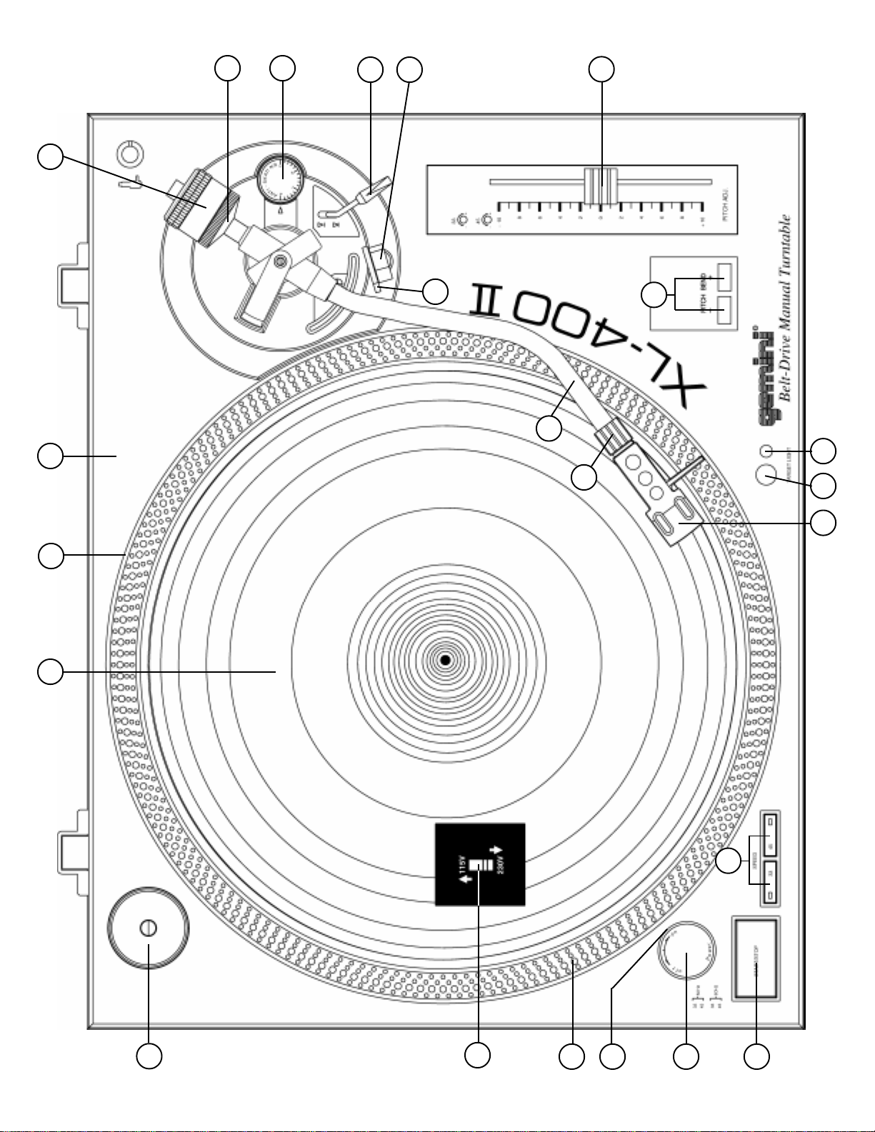
Montaje y configuración
NOTA: VÉASE LA FIG. 1 (PÁGINA 1) PARA NÚMEROS DE PIEZA Y
UBICACIONES.
INSTALACIÓN DEL TOCADISCO:
1. Ponga la BASE DEL TOCADISCO - TURNTABLE BASE (1) sobre una
superficie plana y nivelada sin vibraciones. Trate de colocar la unidad lo
mas alejado posible de los altoparlantes. Mantenga la unidad alejada
de la exposición directa del Sol, calor, humedad o suciedad. Mantenga
la unidad bien ventilada. Use la patas del tocadisco para estabilizar la
unidad en sentido horizontal.
2. Cerciórese de que el SELECTOR DE VOLTAJE - VOLTAGE SELEC-
TOR (3) (colocado en la BASE DEL TOCADISCO) esté arreglado para
el voltaje correcto. ADVERTENCIA: Si trata de hacer funcionar el
tocadisco con el voltaje incorrecto, corre el riesgo de dañarlo.
3. Después de comprobar que se hayan quitado todos los materiales de
embalaje, coloque el PLATO - PLATTER (2) suavemente en el huso
central de la BASE DEL TOCADISCO - TURNTABLE BASE (1).
4. La correa está asegurada al fondo del disco del tocadisco pero debe
ser asegurada al eje del motor. Haga girar el disco hasta que se vea el
eje; después ponga los dedos en los orificios en la parte superior del
disco, busque y agarre la correa de caucho y asegúrela al eje del motor.
5. Coloque la ESTERA DE GOMA - RUBBER MAT (4) sobre el PLATO -
PLATTER (2).
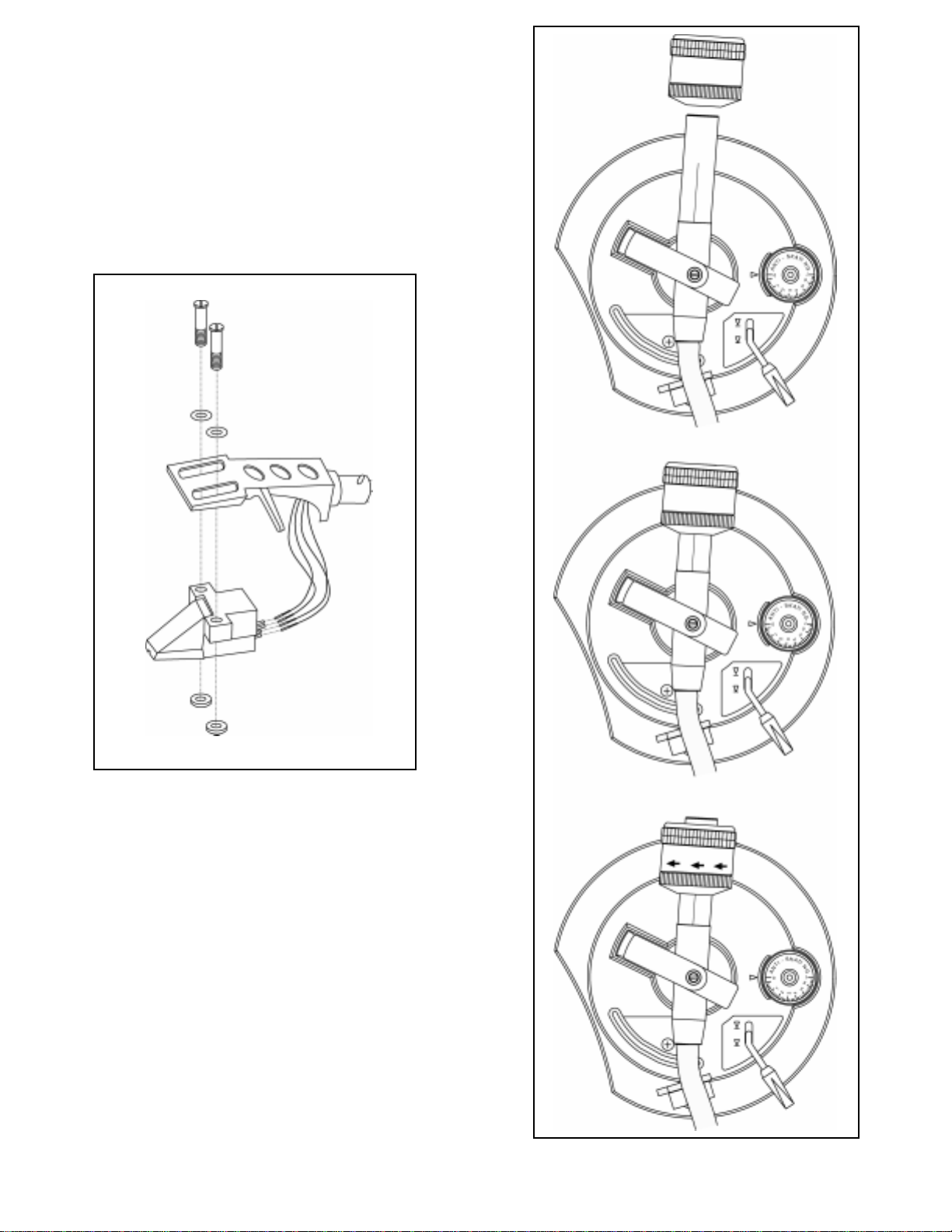
INSTALACIÓN DEL CARTUCHO: (VÉASE LA FIG. 2)
Debido a que todos los cartuchos son de diseño distinto, sírvase referirse a
las instrucciones de su cartucho específico, para garantizar la instalación
correcta.
1. Conecte los alambres conductores a los terminales del cartucho. Para
su conveniencia, los terminales de la mayoría de los cartuchos están
codificados por colores. Conecte cada alambre conductor al terminal
del mismo color.
Blanco (I+)..............................Canal izquierdo +
Azul (I-)...................................Canal izquierdo -
Rojo (D+)................................Canal derecho +
Verde (D-)...............................Canal derecho -
2. Monte el cartucho dentro del PORTAFONOCAPTOR - HEADSHELL (5)
y apriételo con los tornillos incluidos con el cartucho.
ATENCIÓN USADORES DE LOS CARTUCHOS STANTON 680
Al usar un cartucho Stanton 680 o cartucho similar, en el cual el cuerpo
se conectado a tierra a un terminal del cartucho, quite la correa de
tierra del cuerpo del cartucho hacia el terminal de tierra del cartucho.
Al no hacer esto puede resultar en zumbido excesivo.
INSTALACIÓN DEL PORTAFONOCAPTOR:
Inserte el PORTAFONOCAPTOR - HEADSHELL (5) en la parte delantera
del BRAZO DE FONOCAPTOR - TONE ARM (6) tubular. Sosteniendo el
PORTAFONOCAPTOR firmemente en posición horizontal, gire la TUERCA
FIADORA - LOCKING NUT (7) hacia la izquierda hasta que el
PORTAFONOCAPTOR se haya asegurado en posición.
INSTALACIÓN DEL CONTRAPESO: (VÉASE LA FIG. 3)
1. Deslice el CONTRAPESO - COUNTERWEIGHT (8) sobre la parte
posterior del BRAZO DEL FONOCAPTOR - TONE ARM (6) con la
medida de la aguja numerada hacia el frente.
2. Gire el CONTRAPESO - COUNTERWEIGHT (8) ligeramente hacia la
izquierda para enroscarlo en la parte posterior del BRAZO DE
FONOCAPTOR - TONE ARM (6).
AJUSTE DEL EQUILIBRIO CERO (0) HORIZONTAL Y
PRESIÓN DE LA AGUJA:
1. Sin tocar la punta de la aguja, quite el protector de aguja (si el de su
cartucho es removible).
2. Suelte el SUJETABRAZO - ARM CLAMP (9) y levante el BRAZO DE
FONOCAPTOR - TONE ARM (6) del DESCANSILLO - ARM REST (10).
3. Si el CONTRAPESO - COUNTERWEIGHT (8) se avanza hacia la
izquierda, se bajará el lado del cartucho del BRAZO DE FONOCAPTOR
- TONE ARM (6). Si el CONTRAPESO se avanza hacia la derecha
ocurrirá lo contrario. Gire el CONTRAPESO hacia la derecha o la
izquierda según sea necesario hasta que el BRAZO DE FONOCAPTOR
esté horizontalmente equilibrado. Ese equilibrio es fácil de determinar;
espere el punto en que el BRAZO DE FONOCAPTOR “flote”
libremente.
4. Coloque el BRAZO DE FONOCAPTOR - TONE ARM (6) sobre el
DESCANSILLO - ARM REST (10) y asegurelo en posición con el
SUJETABRAZO - ARM CLAMP (9).
5. Con el BRAZO DE FONOCAPTOR enganchado en el DESCANSILLO -
ARM REST (10), sostenga el CONTRAPESO - COUNTERWEIGHT (8)
en una mano y gire el ANILLO DE PRESIÓN DEL ESTILETE - STYLUS
PRESSURE RING (11) hasta que el número “0” en el anillo se alinee con
la línea central del eje trasero del BRAZO DE FONOCAPTOR. El
equilibrio horizontal en cero (0) deberá quedar completo.
6. Flote de nuevo el BRAZO DE FONOCAPTOR para asegurarse que se
haya obtenido el equilibro horizontal en cero (0). Si no se ha mantenido
este equilibrio, repita los pasos de contrapeso 3 al 5.
7. Después de ajustar el equilibrio cero (0) horizontal, gire el
CONTRAPESO - COUNTERWEIGHT (8) equilibrado hacia la izquierda
hasta que aparezca en el ARO DE PRESIÓN DE AGUJA - STYLUS
PRESSURE RING (11) la presión de aguja recomendada del fabricante
del cartucho en el punto donde coincide con la línea central del eje
posterior del BRAZO DE FONOCAPTOR - TONE ARM (6).

Page 9
AJUSTE DEL CONTROL ANTIDESLIZANTE:
Fije el CONTROL ANTIDESLIZANTE - ANTI-SKATING CONTROL (12) al
mismo valor que la presión de la aguja.
INSTALACIÓN DE LA TAPA CONTRA POLVOS:
1. Instale las bisagras en la cubierta.
2. Sostenga la tapa contra polvos en posición directamente arriba del
tocadisco y deslice las bases de las bisagras en los portabisagras
montados en el panel posterior.
3. Siempre levante la tapa contra polvos antes de quitarla.
4. Evite abrir y cerrar la tapa contra polvos cuando el tocadisco está en
funcionamiento, ya que podría ocurrir vibración indeseable y saltos de
la aguja.
CONEXIONES:
1. Conecte el enchufe CA en un tomacorriente apropiado.
2. Véase el Cuadro A para las conexiones apropiadas de los enchufes de
salida RCA y el conector a tierra. Cerciórese de que todos los enchufes
estén firmemente conectados en los jack apropiados (entradas
fonográficas). Para reducir el zumbido, cerciórese de que la orejeta a
tierra esté firmemente conectado al tornillo de tierra.
CUADRO A
Instrucciones de operación
OPERACIÓN BÁSICA:
1. Ponga un disco sobre la ESTERA DE GOMA - RUBBER MAT (4) que
descansa sobre el PLATO - PLATTER (2).
2. Seleccione la velocidad deseada, oprimiendo el BOTÓN SELECTOR
DE VELOCIDAD - SPEED SELECTOR (15) de 33 ó 45.
3. Ponga el INTERRUPTOR DE ENERGÍA - POWER (13) en la posición
de “ENCENDIDO”, en cuyo momento se encenderán el iluminador
estroboscópico (incorporado en el INTERRUPTOR DE ENERGÍA y el
indicador de velocidad (para la velocidad seleccionada).
4. Quite el protector de aguja (si se aplica a su cartucho).
5. Suelte el SUJETABRAZO - ARM CLAMP (9) que se encuentra en el
DESCANSILLO - ARM REST (10).
6. Oprima el BOTÓN DE ARRANQUE/PARADA - START STOP (14). El
PLATO - PLATTER (2) del tocadisco empezará a girar.
7. Oprima la PALANCA DE INDICACION - CUE LEVER (16) en la
posición de “ARRIBA”.
8. Sitúe el brazo de fonocaptor arriba del surco deseado en el disco y
ponga la PALANCA DE INDICACION en la posición de “ABAJO”. El
BRAZO DE FONOCAPTOR - TONE ARM (6) se bajará lentamente
sobre el disco en cuyo momento empezará a reproducir.
9. Una vez que haya terminado de reproducir, levante el BRAZO DE
FONOCAPTOR - TONE ARM (6), MUEVALO hacia el DESCANSILLO -
ARM REST (10) y fíjelo con el SUJETABRAZO - ARM CLAMP (9).
10.Ahora tiene la opción de apagar la unidad, pasando el INTERRUPTOR
DE ENERGÍA - POWER (13) a la posición de “APAGADO” o de detener
el PLATO - PLATTER (2), oprimiendo el BOTÓN DE ARRANQUE/
PARADA - START STOP (14).
INTERRUPCIÓN DE LA REPRODUCCIÓN:
1. Oprimiendo la PALANCA DE INDICACION - CUE LEVER (16) a la
posición de “ARRIBA”, causara que el BRAZO DE FONOCAPTOR -
TONE ARM (6) se levantará y se detengá la reproducción.
2. Oprimiendo la PALANCA DE INDICACION - CUE LEVER (16) a la
posición de “ABAJO” causara que el BRAZO DE FONOCAPTOR -
TONE ARM (6) se baje lentamente sobre el disco en el lugar donde se
interrumpió la reproducción.
REPRODUCCIÓN DE DISCOS DE 45 RPM:
1. Para reproducir un disco de 45 rpm con un agujero central más grande,
ponga primero el ADAPTADOR DE 45 - 45 ADAPTER (17) en el huso
central.
2. Cerciórese de que se haya oprimido el BOTÓN SELECTOR DE
VELOCIDAD - SPEED SELECTOR (15) 45 y que esté iluminado el
indicador de velocidad 45.
LUZ DE POSICIÓN:
1. Oprimir firmemente el INTERRUPTOR DE LUZ DE POSICIÓN -
TARGET LIGHT SWITCH (18), y la LUZ DE POSICIÓN - TARGET
LIGHT (19) iluminará la punta de la aguja.
2. Cuando no esté en uso, se debería apagar la LUZ DE POSICIÓN.
AJUSTE DEL CONTROL DE TONO:
1. El equipo XL-400 II está dotado de un CONTROL DE TONO - PITCH
CONTROL (21). Cuando el CONTROL DE TONO se encuentra en la
posición encentrada, la velocidad será cerca de 33 ó 45, según el
BOTÓN SELECTOR DE VELOCIDAD - SPEED SELECTOR (15) que
se haya oprimido.
2. Cuando el CONTROL DE TONO - PITCH CONTROL (21) está en una
posición descentrada, el paso podrá variar en ±10%, según la posición
del CONTROL DE TONO.
3. El PLATO - PLATTER (2) está dotado de una TIRA INDICADORA DE
RPM ESTROBOSCÓPICA - STROBE RPM INDICATOR STRIP (22) y
el INTERRUPTOR DE ENERGÍA - POWER (13) contiene LUCES
ESTROBOSCÓPICAS - STROBE LIGHTS (23) incorporadas. Cuando
el PLATO - PLATTER (2) gira, las LUCES ESTROBOSCÓPICAS
iluminan la TIRA INDICADORA DE RPM ESTROBOSCÓPICA. La fila
inferior de puntos parecerá estar estacionaria cuando la velocidad del
plato sea exactamente 45 RPM. La segunda fila del fondo parecerá
estar estacionaria a 33 RPM.
BOTONES DE AFINACIÓN DEL TONO:
1. El hecho de apretar los botones PITCH BEND (20) alza o baja
automáticamente el tono sin cambiar la posición de la llave corrediza.
Soltando los botones, se vuelve el tono a la graduación de la llave
corrediza. Se puede utilizar esta función para igualar la afinación del
tono cuando se mezclan canciones.
Especificaciones
SECCIÓN DE TOCADISCO:
Tipo......................................Tocadisco manual de transmisión por correa
Método de transmisión.....................................Transmisión por correa
Motor........................................................................Motor de DC
Plato.....................................Troquelado de aluminio, 332 mm de diám.
Velocidad..............................................................33 1/3 or 45 RPM
Gimoteo y tremolación.................................................0.15% WRMS*
*Este valor se refiere al conjunto de tocadisco y plato solamente, y excluye
los efectos de los discos, cartuchos o brazos de fonocaptor.
SECCIÓN DE BRAZO DE FONOCAPTOR:
Tipo..............................................Brazo en S equilibrado estáticamente
Proyección................................................................................15.2 mm
Gama de ajuste de presión de la aguja..................................0 - 5 g
Gama aplicable de peso de cartucho............................................6 - 10 g
Peso del portafonocaptor...............................................................5.6 g
GENERALIDADES:
Fuente de alimentación............................................115V~60Hz/230V~50Hz
Consumo de energía.................................................................15 vatios
Dimensiones.........................................................450 x 152 x 352 mm
Peso...................................................................................7,7 kg
Las especificaciones están sujetas a cambio sin previo aviso. El peso y las
dimensiones indicados son aproximaciones.
I (BLANCO)
D (ROJO)
TIERRA (Orejeta de paleta)
MEZCLADOR O RECEPTOR
CONECTORES DE SALIDA I CANAL DEL FONÓGRAFO
D CANAL DEL FONÓGRAFO
Tornillo de TIERRA

Page 10
Introduction
Nos félicitations à l’occasion de votre achat cette table-tournante Gemini
XL-400 II. Ce table-tournante très moderne inclut les caractéristiques
technologiques les plus récentes. Avant de l’employer, lisez attentivement
toutes les instructions.
Caractéristiques
• Commande de la hauteur tonale ±10%
• Source lumineuse stroboscopique
• Commutateur marche/arrêt
Précautions
1. Il est important de lire toutes les instructions de fonctionnement doivent
être lues avant de vous servir de cet appareil.
2. Pour réduire le risque de chocs électriques, prière de ne pas ouvrir
l'appareil. Il ne contient pas DE PIÈCES À REMPLACER PAR
L'UTILISATEUR À L'INTÉRIEUR. Prière de contacter le Service
technique de Gemini ou votre concessionnaire homologué pour parler à
un technicien homologué.
3. Les roulements du bras de lecture ont été ajustés et scellés à l’usine.
Toute tentative d’ajustement ou de réglage annulera la garantie.
4. Avant de faire les branchements, vérifiez que l’appareil n’est pas sous
tension.
5. Le câblage doit avoir une faible capacité; il doit être blindé et avoir la
bonne longueur. Tous les jacks et fiches doivent être bien serrés et
convenablement branchés.
6. Commencez toujours en ayant les commandes des régleurs du niveau
acoustique/volume réglées sur minimum et la (les) commande(s) du
volume des haut-parleurs sur OFF (arrêt). Attendez 8 à 10 secondes
avant d’accroître le volume des haut-parleurs pour prévenir le “bruit”
transitoire qui pourrait endommager des haut-parleurs.
7. Protégez cet appareil contre la pluie et l’humidité.
8. N’utilisez aucun produit de nettoyage ou lubrifiant pulvérisé sur les
commandes ou interrupteurs.
Liste des pièces
Table-tournante.............................................................................1
Plateau du table-tournante............................................................1
Tapis en caoutchouc.....................................................................1
Couvercle anti-poussière..............................................................1
Articulation du couvercle anti-poussière........................................2
Adaptateur 45 RPM........................................................................1
Contrepoids...................................................................................1
Coquille pour aiguille.....................................................................1
Montage et configuration
NOTA: VOIR LA FIGURE 1 (PAGE 1) POUR LES NUMEROS DES
PIECES ET LES EMPLACEMENTS.
INSTALLATION DU TABLE-TOURNANTE:
1. Placez l’EMBASE DE LA TABLE TOURNANTE - TURNTABLE BASE
(1) sur une surface plate et équilibrée sans vibrations. Essayez de
placer l’appareil aussi loin que possible des haut-parleurs. Protégez
l’appareil contre les rayons directs du soleil, la chaleur, l’humidité et les
saletés. Assurez une bonne ventilation pour l’appareil. Utilisez les pieds
pour stabiliser l’appareil horizontalement.
2. Assurez-vous que le SELECTEUR DE LA TENSION - VOLTAGE
SELECTOR (3) (situé sur l’EMBASE DE LA TABLE TOURNANTE)
occupe le réglage de tension correct. AVERTISSEMENT: Si vous
essayez de faire fonctionner la table tournante avec une tension
incorrecte, vous risquez d’endommager votre table tournante.
3. Après voir vérifié que tout l’emballage a été enlevé, mettez le PLATEAU
- PLATTER (2) soigneusement sur l’axe central de l’ EMBASE DU
TABLE-TOURNANTE- TURNTABLE BASE (1).
4. La courroie est fixée au fond du plateau mais doit être attachée à l’arbre
du moteur. Faites tourner le plateau jusqu’à ce que l’arbre soit visible;
ensuite, introduisez les doigts dans les trous au sommet du plateau,
cherchez et saisissez la courroie de caoutchouc et attachez-la à l’arbre
du moteur.
5. Placez le TAPIS EN CAOUTCHOUC - RUBBER MAT (4) sur le
PLATEAU - PLATTER (2).
INSTALLATION DE LA CARTOUCHE:
(VOIR LA FIGURE 2)
Etant donné que toutes les cartouches ont leurs propres particularités,
consultez les instructions de votre cartouche pour vous assurer d’une
bonne installation.
1. Branchez les fils aux bornes de la cartouche. Pour vous faciliter la
tâche, les bornes de la plupart des cartouches sont codées par
couleurs. Branchez chaque fil à la borne de la même couleur.
Blanc (L+)................................Canal gauche +
Bleu (L-).....................................Canal gauche -
Rouge (R+)................................Canal droit +
Vert (R-).....................................Canal droit -
2. Installez la cartouche dans LA COQUILLE - HEADSHELL (5) et serrez-
la bien avec les vis fournies avec la cartouche.
ATTENTION AUX UTILISATEURS
DE LA CARTOUCHE STANTON 680
Lorsque vous utilisez une cartouche Stanton 680 ou semblable, pour
laquelle le corps est mis à la masse à une borne de la cartouche,
enlevez la liaison de mise à la masse du corps de la cartouche allant à
la borne de mise à la masse de la cartouche. Un RONFLEMENT
excessif se produira si vous ne le faites pas.
INSTALLATION DE LA COQUILLE:
Introduisez LA COQUILLE - HEADSHELL (5) sur le devant du BRAS DE
LECTURE - TONE ARM (6) tubulaire. Tout en tenant LA COQUILLE
fermement dans la position horizontale, tournez l’ECROU DE BLOCAGE -
LOCKING NUT (7) dans le sens antihoraire jusqu’à ce que LA COQUILLE
soit verrouillée en place.
INSTALLATION DU CONTREPOIDS: (VOIR LA FIGURE 3)
1. Glissez le CONTREPOIDS - COUNTERWEIGHT (8) sur l’extrémité
arrière du BRAS DE LECTURE - TONE ARM (6), la jauge de l’aiguille
numérotée étant tournée vers l’avant.
2. Tournez le CONTREPOIDS - COUNTERWEIGHT (8) légèrement dans
le sens antihoraire pour le visser sur l'extrémité arrière du BRAS DE
LECTURE - TONE ARM (6).
REGLAGE DE L’EQUILIBRE ZERO (0) HORIZONTAL ET
DE LA PRESSION DE L’AIGUILLE:
1. Sans toucher la pointe de l’aiguille, enlevez la protection de l’aiguille (si
celle de votre cartouche est détachable).
2. Desserrez le SERRE-BRAS - ARM CLAMP (9) et soulevez le BRAS DE
LECTURE - TONE ARM (6) du PORTE-BRAS - ARM REST (10).
3. L’avancement dans le sens inverse des aiguilles d’une montre du
CONTREPOIDS - COUNTERWEIGHT (8) produira la descente de la
cellule de lecture montée sur le BRAS DE LECTURE - TONE ARM (6).
L’avancement dans le sens horaire des aiguilles d’une montre produira
l’opposé. Tournez le CONTREPOIDS dans le sens horaire ou dans le
sens inverse des aiguilles d’une montre selon le besoin, jusqu’à ce que
le BRAS DE LECTURE soit équilibré horizontalement. Ce moment se
produit, et vous le verrez facilement, lorsque le BRAS DE LECTURE
“flotte” librement.
4. Placez le BRAS DE LECTURE - TONE ARM (6) sur le PORTE-BRAS -
ARM REST (10) bloquez-le en place avec le SERRE-BRAS - ARM
CLAMP (9).
5. Le BRAS DE LECTURE - TONE ARM (6) étant verrouillé sur le
PORTE-BRAS - ARM REST (10), stabilisez le CONTREPOIDS -
COUNTERWEIGHT (8) avec une main tout en tournant l'ANNEAU DE
PRESSION DE L'AIGUILLE - STYLUS PRESSURE RING (11) jusqu'à

Page 11
ce que le numéro "0" sur l'anneau s'aligne avec la ligne médiane sur
l'arbre arrière du BRAS DE LECTURE. L'équilibre zéro horizontal (0)
devrait être complété.
6. Faites flotter le BRAS DE LECTURE de nouveau pour vous assurer de
l'équilibre zéro horizontal (0). Si l'équilibre zéro n'est pas maintenu,
répétez les étapes 3-5 du contrepoids.
7. Après le réglage de l’équilibre zéro (0) horizontal, tournez le
CONTREPOIDS - COUNTERWEIGHT (8) équilibré dans le sens
inverse des aguilles d’une montre jusqu’à ce que la pression de l’aiguille
recommandée par le fabricant de la cellule de lecture apparaisse sur la
BAGUE DE PRESSION DE L’AIGUILLE - STYLUS PRESSURE RING
(11) là où elle rencontre la ligne médiane de l’arbre arrière du BRAS DE
LECTURE - TONE ARM (6).
REGLAGE DE LA COMMANDE ANTI-DERAPAGE:
Mettez la COMMANDE ANTI-DERAPAGE - ANTI-SKATING CONTROL
(12) à la même valeur que celle de la pression de l’aiguille.
INSTALLATION DU COUVERCLE ANTI-POUSSIERE:
1. Montez les charnières sur le couvercle anti-poussière.
2. Tenez le couvercle anti-poussière en position, directement au-dessus
du table-tournante, et glissez les bases des articulations dans les porte-
articulations se trouvant sur le panneau arrière.
3. Soulevez toujours le couvercle anti-poussière avant son enlèvement.
4. N’ouvrez et ne fermez pas le couvercle durant le fonctionnement du
tourne-disque. Ceci pourrait produire des vibrations indésirées et le
dérapage de l’aiguille.
CONNEXIONS:
1. Branchez la fiche à courant alternatif à une prise adéquate.
2. Voir la Table A pour les connexions correctes des fiches RCA de sortie
et du connecteur de mise à la terre. Assurez-vous que toutes les fiches
sont solidement raccordées dans les jacks corrects (entrées phono).
Pour réduire le ronronnement, assurez-vous que l'oreille de mise à la
terre se branche solidement à la vis de mise à la terre.
TABLEAU A
Mode d’emploi
FONCTIONNEMENT DE BASE:
1. Placez un disque sur le TAPIS EN CAOUTCHOUC - RUBBER MAT (4)
se trouvant sur le PLATEAU - PLATTER (2).
2. Choisissez la vitesse désirée en appuyant sur le SELECTEUR DE
VITESSE - SPEED SELECTOR (15) de 33 ou de 45.
3. Mettez l’INTERRUPTEUR DE MISE SOUS TENSION - POWER (13)
sur la position “ON” (Sous tension); à ce moment, la source lumineuse
stroboscopique (intégrée à l’INTERRUPTEUR DE MISE SOUS
TENSION et l’indicateur de vitesse (pour la vitesse choisie) s’allumera.
4. Enlevez la protection de l’aiguille (si elle fait partie de votre cartouche).
5. Libérez le SERRE-BRAS - ARM CLAMP (9) qui se trouve sur le
PORTE-BRAS - ARM REST (10).
6. Appuyez sur le BOUTON MARCHE/ARRET - START STOP (14). Le
PLATEAU - PLATTER (2) du table-tournante commencera à tourner.
7. Poussez le LEVIER DE COMMANDE - CUE LEVER (16) vers la
position “UP” (haut).
8. Positionnez le bras de lecture au-dessus du sillon désiré du disque et
poussez le LEVIER DE COMMANDE - CUE LEVER (16) vers la
position “DOWN” (Bas). Le BRAS DE LECTURE - TONE ARM (6)
descendra lentement et déposera l’aiguille sur le disque; à ce moment,
vous entendrez l’enregistrement.
9. Une fois l’enregistrement terminé, soulevez le BRAS DE LECTURE -
TONE ARM (6), guidez-le vers le PORTE-BRAS - ARM REST (10) et
bloquez-le à l’aide du SERRE-BRAS - ARM CLAMP (9).
10.Maintenant, vous avez le choix de mettre l’appareil hors tension en
tournant l’INTERRUPTEUR DE MISE SOUS TENSION - POWER (13)
sur la position “OFF” (hors tension) ou d’arrêter le PLATEAU -
PLATTER (2) en appuyant sur le BOUTON MARCHE/ARRET - START
STOP (14).
MARCHE INTERROMPUE:
1. Lorsque vous poussez le LEVIER DE COMMANDE - CUE LEVER (16)
vers la position “UP” (haut), le BRAS DE LECTURE - TONE ARM (6)
montera et arrêtera l’audio.
2. Lorsque vous poussez le LEVIER DE COMMANDE - CUE LEVER vers
la position “DOWN” (bas), le BRAS DE LECTURE - TONE ARM (6)
descendra lentement et déposera l’aiguille sur le disque au point où
l’audio avait été interrompue.
DISQUES DE 45 T/MN:
1. Lorsque vous jouez un disque de 45 t/mn avec un grand trou au centre,
placez d’abord l’ADAPTATEUR 45 - 45 ADAPTER (17) sur l’axe central.
2. Assurez-vous d’appuyer sur le SELECTEUR DE VITESSE - SPEED
SELECTOR (15) 45 et que l’indicateur de vitesse 45 est allumé.
LUMIERE CIBLE:
1. Appuyez bien sur l’INTERRUPTEUR DE LA LUMIÈRE CIBLE -
TARGET LIGHT SWITCH (18), et la LUMIÈRE CIBLE - TARGET
LIGHT (19) allumera la pointe de l’aiguille.
2. Si elle n’est pas utilisée, la LUMIÈRE CIBLE - TARGET LIGHT (19)
devrait être éteinte.
REGLAGE DE LA COMMANDE DE LA HAUTEUR
TONALE:
1. L’appareil XL-400 II est muni d’une COMMANDE DE LA HAUTEUR
TONALE - PITCH CONTROL (21). Lorsque cette COMMANDE DE LA
HAUTEUR TONALE occupe la position centrale, la vitesse
s’approchera de 33 ou de 45 t/mn en fonction du SELECTEUR DE LA
VITESSE - SPEED SELECTOR (15) pressé.
2. Si la COMMANDE DE LA HAUTEUR TONALE - PITCH CONTROL (21)
n’occupe pas la position centrale, la hauteur tonale peut varier de +/-
10% en fonction de la position occupée par cette COMMANDE DE LA
HAUTEUR TONALE.
3. Le PLATEAU - PLATTER (2) est équipé d’une BANDE INDICATRICE
RPM - STROBE RPM INDICATOR STRIP (22) et l’INTERRUPTEUR
DE MISE SOUS TENSION - POWER (13) incorpore des LUMIERES
STROBOSCOPIQUES - STROBE LIGHTS (23). Lorsque le PLATEAU -
PLATTER (2) tourne, les LUMIERES STROBOSCOPIQUES
illuminefont la BANDE INDICATRICE RPM. La rangée de points
inférieure apparaîtra comme étant stationnaire lorsque la vitesse du
plateau est exactement 45 t/mn. La seconde rangée à partir du fond
apparaîtra comme stationnaire à 33 t/mn.
PITCH BEND BUTTONS (COURBURE DU TON):
1. Le fait d’appuyer sur les PITCH BEND (20) (touches de courbure du
ton) augmentera ou réduira automatiquement le ton sans changer le
réglage du ton. Le fait de relâcher les touches remettra le ton sur le
réglage de la glissière. Vous pouvez utiliser cette fonction pour faire
correspondre la courbure du ton lorsque vous mélangez des chansons.
L (BLANC)
R (ROUGE)
Masse (Oeillet)
MELANGEUR OU
RECEPTEUR
CONNECTEURS DE SORTIE
L CANAL PHONO
R CANAL PHONO
Vis de mise à la masse

Page 12
Specifications
PARTIE DU TABLE-TOURNANTE:
Type...Table-tournante manuel à transmission par courroie
Méthode de transmission..........................Transmission par courroie
Moteur......................................................................Moteur DC
Plateau...........Moulé par injection, en aluminium, de 332 mm de diamètre
Vitesse.................................................................33 1/3 ou 45 t/mn
Pleurage et scintillement............................................0,15% WRMS*
*Cette valeur ne correspond qu’au tourne-disque et au plateau, à
l’exclusion des effets produits par les disques, les cartouches ou les bras
de lectures.
PARTIE DU BRAS DE LECTURE:
Type...................................................Bras en S à équilibrage statique
Surplomb.............................................................................15,2 mm
Gamme de réglage de la pression de l’aiguille................de 0 à 5 g
Gamme du poids de la cartouche.................................de 6 à 10 g
Poids de la coquille.....................................................................5,6 g
GENERALITES:
Alimentation électrique.....................................115V~60 Hz/230 V~50 Hz
Consommation.....................................................................15 watts
Dimensions....................................................450 mm x 152 mm x 352 mm
Poids................................................................................7,7 kg
Les spécifications peuvent changer sans préavis. Le poids et les dimen-
sions indiqués sont approximatifs.

Page 13
Introduzione
Complimenti per l’acquisto di questo giradischi Gemini XL-400 II. Questo
giradischi d’avanguardia ha incorporato i componenti più recenti. Prima
dell’uso leggere attentamente queste istruzioni per poter utilizzare il
giradischi in modo corretto.
Caratteristiche principali
• Controllo pitch ±10%
• Spia stroboscopio
• Interruttore soft-touch start/stop
Precauzioni
1. Leggere attentamente queste istruzioni prima di usare il giradischi.
2. Per evitare scosse elettriche non aprire l’unità. INTERNAMENTE NON
CI SONO COMPONENTI SOSTITUIBILI DALL’UTENTE. Per le
riparazioni rivolgersi al Reparto assistenza della Gemini o al rivenditore
autorizzato e consultare un tecnico qualificato.
3. I cuscinetti del braccio sono montati e sigillati dalla fabbrica. Qualsiasi
tentativo di regolazione invaliderà la garanzia.
4. Non inserire la spina prima, di effettuare i collegamenti.
5. I cavi dovrebbero essere a bassa capacità, schermati e di lunghezza
adeguata. Accertarsi che tutte le spine e i jack siano ben fissati e
correttamente collegati.
6. Iniziare sempre con i controlli del livello del volume/fader impostati al
minimo e il controllo/i del volume dell’altoparlante su OFF. Attendere 8/
10 secondi prima di alzare il volume dell’altoparlante per evitare “POP”
transitori che potrebbero causare un danno al crossover/altoparlante.
7. Evitare di esporre l’unità alla pioggia o all’umidità.
8. Non usare detergenti spray o lubrificanti su qualsiasi comando e
interruttore.
Lista dei componenti
Unità giradischi..............................................................................1
Piatto portadisco...........................................................................1
Tappetino di gomma......................................................................1
Cappa.....................................................................................................1
Perni parapolvere..........................................................................2
Adattatore 45giri................................................................................1
Contrappeso...................................................................................1
Fonorivelatore................................................................................1
Montaggio e regolazione
NOTA: VEDERE FIG. 1 (PAGINA 1) PER I NUMERI DEI COMPONENTI E
LA DISPOSIZIONE.
INSTALLAZIONEPORTADISCHI:
1. Mettere la BASE DEL GIRADISCHI - TURNTABLE BASE (1) su di una
superficie piana e stabile senza vibrazione. Cercare di installare l’unità il
più distante possibile dagli altoparlanti. Tenere l’unità distante dalla luce
solare diretta, da fonti di calore, dall’umidità o dalla sporcizia.
Consentire una buona circolazione d’aria. Usare i piedini del giradischi
per stabilizzarlo orizzontalmente.
2. Regolare il SELETTORE VOLTAGGIO - VOLTAGE SELECTOR (3)
(collocato nella BASE DEL GIRADISCHI) nel voltaggio corretto.
AVVERTENZA: Se si tenta di far funzionare il GIRADISCHI con il
voltaggio scorretto, il giradischi potrà dannegiarsi.
3. Dopo aver rimosso l’imballaggio, posizionare con cura il PIATTO
PORTADISCHI - PLATTER (2) sul centro dell’asse della BASE DEL
GIRADISCHI - TURNTABLE BASE (1).
4. La cinghia viene fornite attaccata sul fondo del piatto portadisco ma
deve essere attaccata all’albero del motore. Ruotare il piatto portadisco
finché l’albero del motore è visibile, poi inserire le dita nei fori sulla parte
superiore del piatto, prendere e afferrare la cinghia di gomma e
attaccarla all’albero del motore.
5. Collocare il TAPPETINO DI GOMMA - RUBBER MAT (4) sul PIATTO
PORTADISCO - PLATTER (2).
INSTALLAZIONE CARTUCCIA: (VEDERE FIG. 2)
Dal momento che tutte le cartucce hanno un proprio design, per una
corretta installazione si consiglia di far riferimento alle relative istruzioni.
1. Collegare i conduttori ai terminali della cartuccia. Per praticità, i
terminali della maggior parte delle cartucce hanno colori codificati.
Collegate ciascun conduttore con il terminale del medesimo colore.
Bianco (L+).......................................Canale sinistro+
Blu (L-).............................................Canale sinistro-
Rosso (R+).........................................Canale destro+
Verde (R-).....................................Canale destro-
2. Montate la cartuccia nel FONORIVELATORE - HEADSHELL (5) e
fissatela con le viti in dotazione con la cartuccia.
AVVERTENZA PER GLI UTENTI DELLA CARTUCCIA STANTON 680
Quando si usa una cartuccia Stanton 680 o similare, nei casi in cui il
corpo è a massa con il terminale della cartuccia, trasferire la linguetta
dimassa dalcorpodella cartucciaal terminale dimassa della cartuccia.
Non seguire questa procedura può determinare un eccessivo ronzio.
INSTALLAZIONE DEL FONORIVELATORE:
Inserire il FONORIVELATORE - HEADSHELL (5) nella parte anteriore del
BRACCIO - TONE ARM (6) tubolare. Mentre si tiene saldamente il
FONORIVELATORE in posizione orizzontale, girare in senso antiorario il
CONTRODADO - LOCKING NUT (7) finché il FONORIVELATORE è
posizionato.
INSTALLAZIONE CONTRAPPESO: (VEDERE FIG. 3)
1. Far scivolare il CONTRAPESO - COUNTERWEIGHT (8) sulla parte
posteriore del BRACCIO - TONE ARM (6), con il calibro numerato della
puntina di fronte.
2. Girare un poco il CONTRAPPESO - COUNTERWEIGHT (8) in senso
antiorario, per avvitarlo sulla parte posteriore del BRACCIO - TONE
ARM (6).
REGOLAZIONE BILANCIAMENTO ZERO (0)
ORIZZONTALE E PRESSIONE DELLA PUNTINA:
1. Senza toccare la puntina, rimuovere la protezione della puntina (se la
cartuccia ne ha una staccabile).
2. Rilasciare il FERMA-BRACCIO - ARM CLAMP (9) e mettere fuori il
BRACCIO - TONE ARM (6) dal PORTABRACCIO - ARM REST (10).
3. Spostando in senso antiorario il CONTRAPPESO - COUNTERWEIGHT
(8) il BRACCIO - TONE ARM (6) si abbasserà e in senso orario si avrà
un movimento opposto. Girare in senso orario o antiorario il
CONTRAPPESO fino ad avere il bilanciamento orizzontale del
BRACCIO. Questo può essere facilmente evidenziato osservando il
punto in cui il BRACCIO “fluttua” liberamente.
4. Posizionare il BRACCIO - TONE ARM (6) sul PORTABRACCIO - ARM
REST (10) e bloccarlo in posizione con il FERMA-BRACCIO - ARM
CLAMP (9).
5. Con il BRACCIO - TONE ARM (6) bloccato sui PORTABRACCIO - ARM
REST (10) tenere saldamente con una mano il CONTRAPESO -
COUNTERWEIGHT (8) mentre si ruota l’ANELLO DI PRESSIONE
DELLA PUNTINA - STYLUS PRESSURE RING (11) finché il numero
“0” sull’anello é allineato con la linea centrale dell’asta posteriore del
BRACCIO. In questo modo si é effettuato la regolazione del
bilanciamento zero (0) orizzontale.
6. Sospendere di nuovo il braccio per ottenere il bilanciamento zero (0)
orizzontale. Se non é stato mantenuto il bilanciamento zero (0)
orizzontale ripetere i punti 3-5 del contrappeso.
7. Dopo aver regolato il bilanciamento zero (0) orizzontale, girare in senso
antiorario il CONTRAPPESO - COUNTERWEIGHT (8) che è stato
bilanciato finché sull’ANELLO DI PRESSIONE DELLA PUNTINA -

Page 14
STYLUS PRESSURE RING (11) appare il valore della pressione
consigliata dal fabbricante allineata con la linea centrale dell’asta del
BRACCIO - TONE ARM (6).
REGOLAZIONE DEL CONTROLLO ANTISKATING:
Impostare il CONTROLLO ANTI-SKATING - ANTI-SKATING CONTROL
(12) sullo stesso valore impostato per la pressione della puntina.
INSTALLAZIONE DELLA CAPPA:
1. Colloca i cardini nella coperta o spolverina.
2. Tenere in posizione la cappa, direttamente sopra il giradischi e far
scivolare i perni nei sostegni installati sul retro del pannello.
3. Sollevare sempre la cappa prima di rimuoverlo.
4. Evitare di aprire e chiudere la cappa quando il giradischi è in funzione.
Questo può determinare vibrazioni e salti della puntina.
COLLEGAMENTI:
1. Collegare la spina di alimentazione ad una presa appropriata.
2. Consultare la Tavola A per i corretti collegamenti alle spine di uscita
RCA e alla presa di terra. Assicurarsi che tutte le spine siano ben
inserite nei jack appropriati (ingressi phono). Per ridurre il ronzio,
assicurarsi che il capocorda sia ben collegato alla vite di terra.
TAVOLA A
Istruzioni per il funzionamento
OPERAZIONI PRINCIPALI:
1. Mettere un disco sul TAPPETINO DI GOMMA - RUBBER MAT (4) che
poggia sul PIATTO PORTADISCO - PLATTER (2).
2. Selezionare la velocità desiderata abbassando il PULSANTE
SELETTORE DI VELOCITA’ - SPEED SELECTOR (15) su 33 o 45.
3. Portare su ‘ON’ l’INTERRUTTORE - POWER (13); si illuminano la spia
dello stroboscopio (incorporato nell’INTERRUTTORE e l’indicatore di
velocita’ (per la velocità selezionata).
4. Rimuovere la protezione della cartuccia (se la cartuccia è protetta).
5. Rilasciare il FERMA-BRACCIO - ARM CLAMP (9) che si trova sul
PORTABRACCIO - ARM REST (10).
6. Spingere il PULSANTE START STOP (14). Il PIATTO PORTADISCO -
PLATTER (2) inizierà a girare.
7. Portare la LEVETTA ALZABRACCIO - CUE LEVER (16) su “UP”.
8. Posizionare il braccio sopra la pista desiderata e spingere la LEVETTA
ALZABRACCIO - CUE LEVER (16) su “DOWN”. Il BRACCIO - TONE
ARM (6) si abbasserà lentamente sul disco e inizierà la riproduzione.
9. Alla fine della riproduzione, sollevare il BRACCIO - TONE ARM (6),
rimetterlo sul PORTABRACCIO - ARM REST (10) e fissarlo con il
FERMA-BRACCIO - ARM CLAMP (9).
10.Se si desidera si può spegnere l’alimentazione portando
l’INTERRUTTORE - POWER (13) su “OFF” o fermare il PIATTO
PORTADISCO - PLATTER (2) spingendo il PULSANTE START STOP
(14).
ARRESTO DELLA RIPRODUZIONE:
1. Spingendo la LEVETTA ALZABRACCIO - CUE LEVER (16) su “UP” il
BRACCIO - TONE ARM (6) si alzerà e si arresterà la riproduzione.
2. Spingendo la LEVETTA ALZABRACCIO - CUE LEVER (16) su
“DOWN” il BRACCIO si abbasserà lentamente sul disco nel punto in cui
la riproduzione è stata interrotta.
RIPRODUZIONE A 45 GIRI AL MINUTO:
1. Quando si riproducono dischi a 45 giri con un foro centrale grande,
posizionare prima l’ADATTATORE 45 - 45 ADAPTER (17) sul centro
dell’asse.
2. Assicurarsi che il PULSANTE SELETTORE DI VELOCITA’ - SPEED
SELECTOR (15) 45 sia premuto e che la spia della velocità a 45 giri sia
illuminata.
INDICATORI:
1. Premere l’INTERRUTTORE INDICATORI - TARGET LIGHT SWITCH
(18) e l’INDICATORE - TARGET LIGHT (19) illuminarà la puntina.
2. Quando non si usa, l’INDICATORE dovrebbe essere chiuso.
REGOLAZIONE DEL CONTROLLO PITCH:
1. Il giradischi XL-400 II è dotata di un CONTROLLO PITCH - PITCH
CONTROL (21). Quando il CONTROLLO PITCH si trova nella posizione
centrale, la velocità sarà vicino a 33 o 45 giri a seconda della posizione
del PULSANTE SELETTORE DI VELOCITA’ - SPEED SELECTOR
(15).
2. Quando il CONTROLLO PITCH è fuori centro, il pitch può variare da +/-
10% a seconda della posizione del CONTROLLO PITCH.
3. Il PIATTO PORTADISCO - PLATTER (2) è dotato di una RIGA DI
INDICATORI DELLO STROBOSCOPIO RPM - STROBE RPM
INDICATOR STRIP (22) (giri al minuto) e l’INTERRUTTORE - POWER
(13) ha incorporato le LUCI STROBOSCOPICHE - STROBE LIGHTS
(23). Quando il PIATTO PORTADISCO - PLATTER (2) è in rotazione, le
LUCI STROBOSCOPICHE illuminano la RIGA DI INDICATORI DELLO
STROBOSCOPIO RPM. La riga inferiore di puntini apparirà ferma
quando la velocità del piatto portadischi è esattamente 45 giri. La
seconda riga a partire dal basso sarà ferma a 33 RPM.
PITCH BEND:
1. Premendo i PITCH BEND (20) il tono diventerà più alto o più basso
senza cambiare la posizione della guida. Liberando i tasti, il tono
diventerà di nuovo quello indicato dalla posizione della guida.
Specifiche Tecniche
GIRADISCHI:
Tipo........................Giradischi manuale a trazione a cinghia
Sistema di trasmissione............................Trazione a cinghia
Motore.................................................................Motore DC
Piattoportadisco................Alluminio pressofuso 332 mm Dia.
Velocità..........................................33 1/3 o 45 giri al minuto
Wow e flutter..................................................0.15% WRMS*
* Questi valori si riferiscono solo all’insieme del giradischi e del piatto
portadisco e non includono quindi il carico dei dischi, della cartuccia e del
braccio.
BRACCIO:
Tipo.............................Braccio ad S staticamente equilibrato
Sporgenza...............................................................15.2 mm
Campo regolazione pressione puntina......................0 - 5 g
Campo applicabile peso cartuccia.............................6 - 10 g
Peso fonorivelatore........................................................5.6 g
CARATTERISTICHE:
Alimentazione......................................................115V~60Hz/230V~50Hz
Consumo......................................................................15 Watts
Dimensioni..........................................450mm x 152mm x 352mm
Peso.............................................................................7,7 Kg
Le specifiche sono soggette a cambiamenti senza preavviso. Il peso e le
dimensioni sono indicativi.
L (BIANCO)
R (ROSSO)
GND (Capocorda)
MIXER O RICEVITORI
CONNETTOR USCITA PHONO CANALE L
PHONO CANALE R
Vite GND

Parts of the design of this product may be protected by worldwide patents.
Information in this manual is subject to change without notice and does not represent a commitment on the
part of the vendor. Gemini Sound Products Corp. shall not be liable for any loss or damage whatsoever arising
from the use of information or any error contained in this manual.
No part of this manual may be reproduced, stored in a retrieval system or transmitted, in any form or by any
means, electronic, electrical, mechanical, optical, chemical, including photocopying and recording, for any
purpose without the express written permission of Gemini Sound Products Corp..
It is recommended that all maintenance and service on the product should be carried out by Gemini Sound
Products Corp. or it’s authorized agents. Gemini Sound Products Corp. cannot accept any liability whatsoever
for any loss or damage caused by service, maintenance or repair by unauthorized personnel.
In the U.S.A., if you have any problems with this
unit, call 1-732-969-9000 for customer service. Do
not return equipment to your dealer.
Worldwide Headquarters • 8 Germak Drive, Carteret, NJ 07008 • USA
Tel (732) 969-9000 • Fax (732) 969-9090
France • G.S.L. France • 11, Avenue Leon Harmel, Z.I. Antony, 92160 Antony, France
Tel: + 33 (0) 1 55 59 04 70 • Fax: + 33 (0) 1 55 59 04 80
Germany • Gemini Sound Products GmbH • Ottostrasse 6, 85757 Karlsfeld, Germany
Tel: 08131 - 39171-0 • Fax: 08131 - 39171-9
UK • Gemini Sound Products • Unit C4 Hazleton Industrial Estate, Waterlooville, UK P08 9JU
Tel: 087 087 00880 • Fax: 087 087 00990
Spain • Gemini Sound Products S.A. • Mino, 112, Nave 1, 08223 Terrassa, Barcelona, Spain
Tel: 011-34-93-736-34-00 • Fax: 011-34-93-736-34-01
© Gemini Sound Products Corp. 1999 All Rights Reserved
Table of contents
Languages:
Other Gemini Turntable manuals

Gemini
Gemini CDMP-1500 User manual

Gemini
Gemini XL-120Mkll User manual

Gemini
Gemini TT-03 User manual

Gemini
Gemini TT-04 User manual

Gemini
Gemini CDT-05 MKII User manual

Gemini
Gemini XL-500 II User manual

Gemini
Gemini TT-900 User manual

Gemini
Gemini TT-1000 User manual

Gemini
Gemini PT-2000 III User manual

Gemini
Gemini XL-500 ll User manual

Gemini
Gemini SA-600 User manual

Gemini
Gemini XL-120 MkII User manual

Gemini
Gemini XL-500 II User manual

Gemini
Gemini TT-1000 User manual

Gemini
Gemini iTT User manual

Gemini
Gemini PT-2410 User manual

Gemini
Gemini TT-01mkii User manual

Gemini
Gemini XL-20 User manual

Gemini
Gemini XL 500 II XL-500II XL-500II User manual

Gemini
Gemini DJ Q1300 User manual