General 50-090RK MI Parts list manual

SETUP & OPERATION MANUAL
10” JOB SITE SAW /
CONTRACTOR SAW
EATURES
50-090RK: OB SITE SAW, INCLUDES
50-090R SAW AND FOLDING STAND
#50-095.
50-090RC: CONTRACTOR SAW, INCLUDES
50-090R SAW AND FIXED LEG STEEL STAND
#50-096.
Heavy-duty, precision cast-iron, ribbed table
with miter gauge t-slots.
2 1/2” dust port allows easy connection
to a dust collection system.
Deluxe, quick adjusting miter gauge.
Ruggedly built saw carriage.
Arbor driven by a two step belt, ensuring
straightness and accuracy when the blade
is tilted.
Heavy-duty folding stand with wheels for
easy mobility and storage (50-090RK M1).
Sturdy open base steel stand
(50-090RC M1)
.
Combination riving style splitter and see
through blade guard with anti-kickback
pawls, and a second European style riving
knife also included.
Includes new Excalibur aluminum T-fence
style precision rip fence system.
Smooth running belt driven 2 HP induction
motor for quiet start-up and operation, and
longer running life.
Large paddle-style stop switch.
VERSION 1_REVISION 1 - August 17/11
© Copyright General® International 08/2011
SPECI ICATIONS
BLADE DIAMETER
10’’ (254 mm)
ARBOR DIAMETER
5⁄8” (16 mm)
MAXIMUM DEPTH O CUT AT 90°
31⁄4” (83 mm)
MAXIMUM DEPTH O CUT AT 45°
25⁄16’’ (59 mm)
MAXIMUM RIP TO RIGHT O BLADE
36’’ (914 mm)
DADO CAPACITY
3⁄4” (19 mm)
ARBOR SPEED
3450 RPM
TABLE SIZE (W/O EXTENSION WINGS)
20’’ x 25 1⁄4” (508 x 641 mm)
EXTENSION WINGS SIZE (2)
10” x 25 1⁄4” (254 x 641 mm)
DUST PORT DIAMETER
21⁄2” (64 mm)
OVERALL DIMENSIONS (L X W X H)
69” x 38” x 42 1⁄2” (1745 x 965 x 1080 mm) -50-090RK
66 1⁄2” x 38” x 43 1⁄2” (1690 x 965 x 1150 mm) -50-090RC
MOTOR (PRE-WIRED 110 V)
2 HP, 110 / 220 V, 13/6.5 A
WEIGHT
233 LBS (106 kg)
-50-090RK
217 LBS (98.5 kg)
-50-090RC
MODEL
#50-090RK M1
#50-090RC M1
50-090RK
50-090RC
- Left tilt with riving knife

HANK YOU for choosing this General International model 50-090R table saw.
This saw has been carefully tested and inspected before shipment and if properly used and
maintained, will provide you with years of reliable service. To ensure optimum performance
and trouble-free operation, and to get the most from your investment, please take the time to
read this manual before assembling, installing and operating the unit.
The manual’s purpose is to familiarize you with the safe operation, basic function, and features
of this saw as well as the set-up, maintenance and identification of its parts and components.
This manual is not intended as a substitute for formal woodworking instruction, nor to offer the
user instruction in the craft of woodworking. If you are not sure about the safety of performing
a certain operation or procedure, do not proceed until you can confirm, from knowledgeable
and qualified sources, that it is safe to do so.
Once you’ve read through these instructions, keep this manual handy for future reference.
All omponent parts of General® International ma hinery are arefully tested and inspe ted during all stages of
produ tion, and ea h ma hine is thoroughly inspe ted upon ompletion of assembly. Be ause of our ommit-
ment to quality and ustomer satisfa tion, General® International agrees to repair or repla e, within a period of 24
months from date of pur hase, any genuine part or parts whi h, upon examination, prove to be defe tive in work-
manship or material. In order to obtain this warranty, all defe tive parts must be returned freight pre-paid to
General® International Mfg. Co., Ltd. Repairs attempted without our written authorization will void this warranty.
GENERAL ® INTERNATIONAL WARRANTY
Disclaimer: The information and specifications in this manual pertain to
the unit as it was supplied from the factory at the time of printing.
Because we are committed to making constant improvements, General
International reserves the right to make changes to components, parts
or features of this unit as deemed necessary, without prior notice and
without obligation to install any such changes on previously delivered
units. Reasonable care is taken at the factory to ensure that the specifi-
cations and information in this manual corresponds with that of the unit
with which it was supplied. However, special orders and “after factory”
modifications may render some or all information in this manual
inapplicable to your machine. urther, as several generations of this
model of saw and several versions of this manual may be in circulation,
if you own an earlier or later version of this unit, this manual may not
depict your machine exactly. If you have any doubts or questions
contact your retailer or our support line with the model and serial
number of your unit for clarification.
GENERAL® INTERNATIONAL
8360 Champ-d’Eau, Montreal (Quebec) Canada H1P 1Y3
Telephone (514) 326-1161 • ax (514) 326-5555 • www.general.ca

GENERAL®FG & GENERAL®INTERNATIONAL WARRANTY
All component parts of General® M G, General® International and Excalibur by General
International ® products are carefully inspected during all stages of production and each unit
is thoroughly inspected upon completion of assembly.
Limited Lifetime Warranty
Because of our commitment to quality and customer satisfaction, General® M G and
General® International agree to repair or replace any part or component which upon exa-
mination, proves to be defective in either workmanship or material to the original purchaser
for the life of the tool. However, the Limited Lifetime Warranty does not over any produ t used
for professional or ommer ial produ tion purposes nor for industrial or edu ational appli a-
tions. Su h ases are overed by our Standard 2-year Limited Warranty only. The Limited
Lifetime Warranty is also subje t to the “Conditions and Ex eptions” as listed below.
Standard 2-Year Limited Warranty
All products not covered by our lifetime warranty including products used in commercial,
industrial and educational applications are warranted for a period of 2 years (24 months) from
the date of purchase. General® M G and General® International agree to repair or replace
any part or component which upon examination, proves to be defective in either workman-
ship or material to the original purchaser during this 2-year warranty period, subject to the
“conditions and exceptions” as listed below.
To file a Claim
To file a claim under our Standard 2-year Limited Warranty or under our Limited Lifetime
Warranty, all defective parts, components or machinery must be returned freight or postage
prepaid to General® International, or to a nearby distributor, repair center or other location
designated by General® International. or further details call our service department at 1-888-
949-1161 or your local distributor for assistance when filing your claim.
Along with the return of the product being claimed for warranty, a copy of the original proof
of purchase and a “letter of claim” must be included (a warranty claim form can also be used
and can be obtained, upon request, from General® International or an authorized distributor)
clearly stating the model and serial number of the unit (if applicable) and including an expla-
nation of the complaint or presumed defect in material or workmanship.
CONDITIONS AND EXCEPTIONS:
This coverage is extended to the original purchaser only. Prior warranty registration is not
required but documented proof of purchase i.e. a copy of original sales invoice or receipt
showing the date and location of the purchase as well as the purchase price paid, must be
provided at the time of claim.
Warranty does not include failures, breakage or defects deemed after inspection by General®
M G or General® International to have been directly or indirectly caused by or resulting from;
improper use, or lack of or improper maintenance, misuse or abuse, negligence, accidents,
damage in handling or transport, or normal wear and tear of any generally considered con-
sumable parts or components.
Repairs made without the written consent of General® Internationallwill void all warranty.

TABLE OF CONTENTS
SAFETY RULES .......................5
ELECTRICAL REQUIRE ENTS ..............6
Grounding instructions . . . . . . . . . . . . . . . . . . . . . . .6
Circuit capacity . . . . . . . . . . . . . . . . . . . . . . . . . . . . .6
Converting the motor to 220V . . . . . . . . . . . . . . . . .6
Extension cords . . . . . . . . . . . . . . . . . . . . . . . . . . . . .6
IDENTIFICATION OF AIN PARTS AND
CO PONENTS .......................7
UNPACKING & SET UP ..................8
Unpacking . . . . . . . . . . . . . . . . . . . . . . . . . . . . . . . . .8
List of contents . . . . . . . . . . . . . . . . . . . . . . . . . . . . . .8
Additional requirements for set up . . . . . . . . . . . . .8
PLACE ENT WITHIN THE SHOP / ESTABLISHING A
SAFETY ZONE ........................9
CLEAN UP ..........................9
ASSE BLY INSTRUCTIONS ..............10
Assemble the folding stand (#50-095) . . . . . . . . .10
Assemble the fixed leg stand (#50-096) . . . . . . . .11
Assemble the saw . . . . . . . . . . . . . . . . . . . . . . . . . .12
Assemble the front fence rails . . . . . . . . . . . . . . . .13
Assemble the rear fence rails . . . . . . . . . . . . . . . .14
Mounttheswitch ...........................14
Install / remove a saw blade .............15
Adjusting the bevel angle pointer .........15
Selecting, install and adjusting riving knife ...15
Selectarivingknife .........................15
Removal/installation . . . . . . . . . . . . . . . . . . . . . . . .16
Centering the splitter/riving knife on the blade .16
Remove/install the blade cover ...........16
Remove ...................................16
Install .....................................17
Remove/install the anti-kickback pawls .....17
Level the table insert ..................17
Align and level the rip fence .............18
Align the rip fence parallel to the blade . . . . . . .18
Align the rip fence 90º to the table . . . . . . . . . . . .18
Level the fence . . . . . . . . . . . . . . . . . . . . . . . . . . . . .18
Adjust & align rip fence pointer ...........19
Connecting to a dust collector ...........19
BASIC ADJUST ENTS AND CONTROLS ......19
Connecting to a power source . . . . . . . . . . . . . . .19
ON / O switch and safety pin . . . . . . . . . . . . . . .20
OPERATING INSTRUCTIONS .............20
Ripping . . . . . . . . . . . . . . . . . . . . . . . . . . . . . . . . . . .20
Bevel ripping . . . . . . . . . . . . . . . . . . . . . . . . . . . . . .21
Ripping small work pieces . . . . . . . . . . . . . . . . . . .21
Cross cutting . . . . . . . . . . . . . . . . . . . . . . . . . . . . . . .21
Align-a-cut . . . . . . . . . . . . . . . . . . . . . . . . . . . . . . . .21
Bevel cross cutting . . . . . . . . . . . . . . . . . . . . . . . . . .22
Adjusting and using the miter gauge .......22
Adding an auxiliary fence to the miter gauge . .22
Miter cuts . . . . . . . . . . . . . . . . . . . . . . . . . . . . . . . . . .23
Compound mitering . . . . . . . . . . . . . . . . . . . . . . . .23
Using a dado head blade ...............23
Instructions for foldin & unfolding the stand
(#50-095) .........................24
RECO ENDED OPTIONAL ACCESSORIES . . . .24
PARTS LIST AND DIAGRA S ..........25 - 35

RULES FOR SAFE OPERATION
To help ensure safe operation, please take a moment to learn the machine’s applications and limitations, as well as poten-
tial hazards. General® International disclaims any real or implied warranty and holds itself harmless for any injury that
may result from improper use of its equipment.
1.Do not operate the saw when tired, distracted, or
under the effects of drugs, alcohol or any medica-
tion that impairs reflexes or alertness.
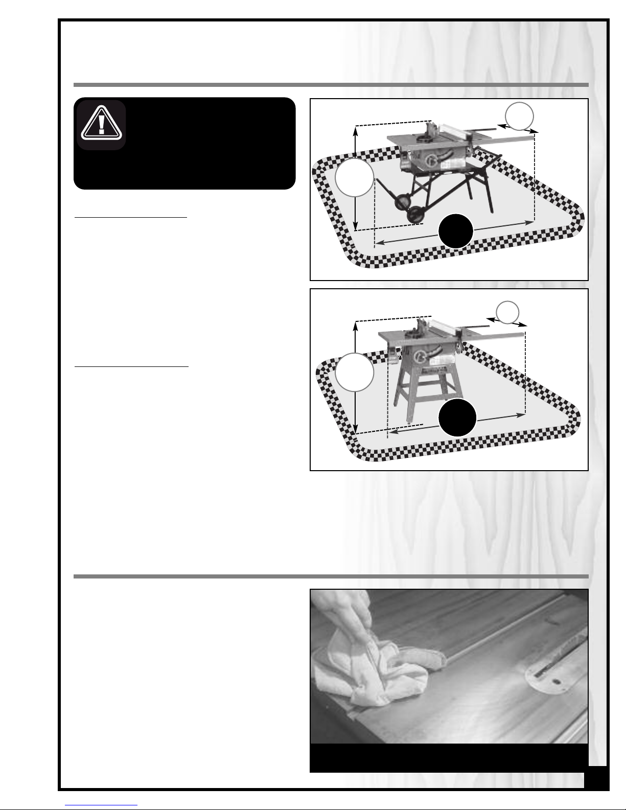
2. The working area should be well lit, clean and free
of debris.
3. Keep children and visitors at a safe distance when
the saw is in operation; do not permit them to
operate the saw.
4. Childproof and tamper proof your shop and all
machinery with locks, master electrical switches
and switch keys, to prevent unauthorized or unsu-
pervised use.
5. Stay alert! Give your work your undivided atten-
tion. Even a momentary distraction can lead to seri-
ous injury.
6. ine particulate dust is a carcinogen that can be
hazardous to health. Work in a well-ventilated area
and whenever possible use a dust collector and
wear eye, ear and respiratory protection devices.
7. Do not wear loose clothing, gloves, bracelets, neck-
laces or other jewelry while the saw is in operation.
Wear protective hair covering to contain long hair
and wear non-slip footwear.
8. Be sure that adjusting wrenches, tools, drinks and
other clutter are removed from the machine and/or
the table surface before operating.
9. Keep hands well away from the blade and all mo-
ving parts. Use a brush, not hands, to clear away
chips and dust.
10. Be sure that the blade is securely installed and in
proper cutting direction before operation.
11. Be sure the blade has gained full operating speed
before beginning to cut.
12. Always use a clean, properly sharpened blade.
Dirty or dull blades are unsafe and can lead to
accidents.
13. If using a power feeder, stop the feeder before stop-
ping the table saw.
14. Do not push or force stock into the blade. The saw
will perform better and more safely when working
at the rate for which it was designed.
15. Use suitable support when cutting stock that does
not have a flat surface. Always hold stock firmly
against the fence when ripping, or against the miter
gauge when cross-cutting.
16. To minimize risk of injury in the event of workpiece
kickback, never stand directly in-line with the blade
or in the potential kickback path of the work piece.
17. Avoid working from awkward or off balance posi-
tions. Do not overreach while cutting; keep both
feet on floor. Never lean over or reach over the
blade and never pull the work piece over the blade
from behind. Use out feed support or have an assis-
tant help when ripping long material.
18. Keep blade guards in place and in working order.
If a guard must be removed for maintenance or
cleaning, be sure it is properly reattached before
using the tool again.
19. Never leave the machine running with the power
on when not in operation.
20. Use of parts and accessories NOT recommended
by
GENERALINTERNATIONAL
may result in equip-
ment malfunction or risk of injury.
21. Never stand on machinery. Serious injury could
result if the tool is tipped over or if the blade is unin-
tentionally contacted.
22. Always disconnect tool from power before servicing
or changing accessories such as blades, or before
performing any maintenance, cleaning or adjust-
ments, or if the machine will be left unattended.
23. Make sure that switch is in "O " position before
plugging in the power cord.
24. Make sure the tool is properly grounded. If equip-
ped with a 3-prong plug it should be used with a
three-pole receptacle. Never remove the third
prong.
25. Do not use this saw for other than its intended use. If
used for other purposes,
GENERALINTERNATIONAL
disclaims any real implied warranty and holds itself
harmless for any injury, which may result from that
use.
5

ELECTRICAL REQUIRE ENTS
BEFORE CONNECTING THE MACHINE TO THE POWER SOURCE, VERIFY THAT THE VOLTAGE OF YOUR POWER SUPPLY CORRE-
SPONDS WITH THE VOLTAGE SPECIFIED ON THE MOTOR I.D. NAMEPLATE. A POWER SOURCE WITH GREATER VOLTAGE THAN
NEEDED CAN RESULT IN SERIOUS IN URY TO THE USER AS WELL AS DAMAGE TO THE MACHINE. IF IN DOUBT, CONTACT A QUAL-
IFIED ELECTRICIAN BEFORE CONNECTING TO THE POWER SOURCE.
THIS TOOL IS FOR INDOOR USE ONLY. DO NOT EXPOSE TO RAIN OR USE IN WET OR DAMP LOCATIONS.
CONVERTING THE OTOR TO 220V
Note: When converting motor voltage on a machine that is
equipped with a magnetic switch, the switch contactor
must also be changed out for one made for the appropri-
ate voltage, as well as the thermal relay/circuit breaker
and “power in” indicator light (if applicable). Failure to
make these necessary modifications to the switch will lead
to malfunction and permanent switch failure.
Should you need to convert your machine’s motor from
110V to 220V power, there is an electrical schematic
drawing on the inside of the motor cover plate. Unless
you are a qualified electrician, we do not recommend
attempting this conversion on your own. If you choose
to do so, you may risk serious personal injury, damage
to the motor and voiding the warranty of your machine.
We suggest you ask your local General International
distributor to recommend qualified electricians in your
area (or perhaps one of their own technicians) who
can make this conversion properly and safely.
EXTENSION CORDS
If you find it necessary to use an extension cord with your
machine, use only 3-wire extension cords that have 3-
prong grounding plug and a matching 3-pole recepta-
cle that accepts the tool’s plug. Repair or replace a
damaged extension cord or plug immediately.
Make sure the cord rating is suitable for the amperage
listed on the motor I.D. plate. An undersized cord will
cause a drop in line voltage resulting in loss of power
and overheating. The accompanying chart shows the
correct size extension cord to be used based on cord
length and motor I.D. plate amp rating. If in doubt, use
the next heavier gauge. The smaller the number, the
heavier the gauge.
6
In the event of an electrical malfunction or short cir-
cuit, grounding reduces the risk of electric shock. The
motor of this machine is wired for 110V single phase
operation and is equipped with a 3-conductor cord
and a 3-prong grounding plug Ato fit a grounded
type receptacle B. Do not remove the 3rd prong
(grounding pin) to make it fit into an old 2-hole wall
socket or extension cord. If an adaptor plug is used C,
it must be attached to the metal screw of the recepta-
cle.
Note: he use of an adaptor plug is illegal in some
areas. Check your local codes. If you have any doubts
or if the supplied plug does not correspond to your
electrical outlet, consult a qualified electrician before
proceeding.
CIRCUIT CAPACITY
Make sure that the wires in your circuit are capable of
handling the amperage draw from your machine, as
well as any other machines that could be operating
on the same circuit. If you are unsure, consult a quali-
fied electrician. If the circuit breaker trips or the fuse
blows regularly, your machine may be operating on a
circuit that is close to its amperage draw capacity.
However, if an unusual amperage draw does not exist
and a power failure still occurs, contact a qualified
technician or our service department.
GROUNDING INSTRUCTIONS
TABLE - INI U GAUGE FOR CORD
A PERE
RATING
TOTAL LENGTH OF CORD IN FEET
110 VOLTS 25 FEET 50 FEET 100 FEET 150 FEET
220 VOLTS 50 FEET 100 FEET 200 FEET 300 FEET
AWG
< 5 -------> 18 16 16 14
6 T 10 -------> 18 16 14 12
10 T 12 -------> 16 16 14 12
12 T 16 -------> 14 12 * NR * NR
* NR = Not Recommended
A
BC

10” JOB SITE SAW / CONTRATOR SAW
50-090RK M1 or 50-090RC M1 (left tilt with riving knife
IDENTIFICATION OF AIN PARTS AND CO PONENTS
A- LE T TABLE EXTENSION
B- MITER GAUGE
C- MAIN TABLE
D- BLADE GUARD AND
SPLITTER ASSEMBLY
E- RIP ENCE
F- RIGHT TABLE EXTENSION
G- REAR RAIL
H- RONT RAIL
I- RIP ENCE LOCKING
HANDLE
- BLADE TILT ADJUSTMENT
HANDWHEEL
K- BEVEL SCALE
L- BLADE HEIGHT
ADJUSTMENT HANDWHEEL
M- MITER GAUGE STORAGE
BRACKET
N- ON/O SWITCH
O- OLDING STAND (50-090RK)
P- IXED LEG STAND (50-090RC)
AB
DE
F
G
J
I
N
L
7
C
H
M
P
50-090RK 1 50-090RC 1
K

LIST OF CONTENTS
Model 50-090R M1: Saw only
Model 50-090RK M1: Saw + folding stand
Model 50-090RC M1: Saw + fixed leg stand
BOX #1 - SAW & COMPONENTS: Qty
A - RONT ENCERAILS...........................1
B - ENCELOCKHANDLE ........................1
C - ENCEBODY ................................1
D - MITERGAUGE ...............................1
E - HANDWHEELS ................................2
F - TOOLBAG ..................................1
G - HARDWAREBAG .............................1
H - BLADE GUARD / SPLITTER ASS’Y . . . . . . . . . . . . . . . . .1
I - TABLEEXTENSIONS ...........................2
- REAR ENCERAILS ............................1
K - TABLEBRACE ................................1
L - SAW BODY WITH MAIN TABLE & SWITCH ASSEMBLY (NO
SHOWN)
BOX #2 - FOLDING STAND (50-090RK M1): Qty
A - PARTIALLY ASSEMBLED OLDING STAND . . . . . . . . . .1
B - VERTICAL SUPPORT LEGS . . . . . . . . . . . . . . . . . . . . . .2
C - SUPPORT LEG MOUNTING HARDWARE . . . . . . . . . . . .1
D - PISTON MOUNTING HARDWARE . . . . . . . . . . . . . . . . .1
E - SAW TO STAND MOUNTING HARDWARE . . . . . . . . . .1
BOX #2 - FIXED LEG STAND (50-090RC M1): Qty
A - STANDLEG ..................................4
B - TOP CROSS BRACE (RONT & BACK)................2
C - TOP CROSS BRACE (SIDE).......................2
D - BOTTOM CROSS BRACE (RONT & BACK)............2
E - BOTTOM CROSS BRACE (SIDE)...................2
F - HARDWAREBAG .............................1
R
UNPACKING
Carefully unpack and remove the unit and its components from its shipping containers and check for missing or
damaged items as per the list contents below.
Note: Please report any damaged or missing items to your General International distributor immediately.
BOX #2
BOX #1
A
B
C
D
EF
G
H
I
J
K
A
B
C
D
E
BOX #2
R
A
B
D
C
E
F
8
UNPACKING & SET UP
ASSE BLY TOOLS PROVIDED
• 2 Arbor blade guard bracket wrenches
•12 mm combination wrench
• 4 Allen wrenches
ADDITIONAL TOOLS NEEDED
• Straightedge
• Large slot & large Phillips screwdrivers
• Socket wrench kit (recommended) & adjustable wrench
• An extra person for help with lifting

PLACE ENT WITHIN THE SHOP /
ESTABLISHING A SAFETY ZONE
PLACE ENT WITHIN THE SHOP
This machine should be installed and operated
only on a solid, flat and stable floor that is able
to support the weight of the saw and the ope-
rator.
Using the dimensions shown as a guideline, plan
for placement within your shop that will allow
the operator to work unencumbered and unob-
structed by foot traffic (either passing shop visi-
tors or other shop workers) or other tools or ma-
chinery.
ESTABLISHING A SAFETY ZONE
or shops with frequent visitors or multiple oper-
ators, it is advisable to establish a safety zone
around shop machinery. A clearly defined “no-
go” zone on the floor around each machine can
help avoid accidents that could cause injury to
either the operator or the shop visitor. It is advis-
able to take a few moments to either paint
(using non-slip paint) or using tape, define on
the floor the limits or perimeter of each
machines safety zone. Take steps to ensure that all operators and shop visitors are aware that these areas are
off limits whenever a machine is running for everyone but the individual operating the unit.
THIS MODEL IS HEAVY. DO NOT OVER-EXERT.
AHOIST OR FORKLIFT WITH STRAPS SHOULD
BE USED TO LIFT THIS MACHINE.
TO LIMIT THE RISK OF SERIOUS IN URY
OR DAMAGE TO THE MACHINE, ANY
EQUIPMENT USED TO LIFT THIS MACHINE
SHOULD HAVE A RATED CAPACITY IN EXCESS OF 233 LBS
(106 KG) FOR 50-090RK & 217 LBS (98.5 KG) FOR
50-090RC.
The protective coating on the saw table prevents
rust from forming during shipping and storage.
Remove it by rubbing with a rag dipped in
kerosene, mineral spirits or paint thinner. (Dispose
of potentially flammable solvent-soaked rags
according to manufacturer’s safety recommen-
dations.)
A putty knife, held flat to avoid scratching the sur-
face, may also be used to scrape off the coating
followed by clean-up with solvent. Avoid rubbing
the saw’s painted surfaces, as many solvent-
based products will remove paint.
To prevent rust, apply a light coating of paste wax
or use regular applications of any after-market
surface protectant or rust inhibitor. Tip: With a screw driver, push a solvent-saturated rag into the T-
slots to remove the grease.
38”
69”
42 ½”
50-090RK 1
38”
66 ½”
43 ½”
50-090RC 1
9
CLEAN UP

10
ASSE BLY INSTRUCTIONS
SERIOUS PERSONAL IN URY COULD OCCUR IF YOU CONNECT THE MACHINE TO THE POWER SOURCE BEFORE YOU HAVE
COMPLETED THE INSTALLATION AND ASSEMBLY STEPS. DO NOT CONNECT THE MACHINE TO THE POWER SOURCE UNTIL
INSTRUCTED TO DO SO.
1. Lay the stand flat on the ground as shown. 2. Raise the handle off the ground and lower the sup-
port legs as shown.
3. Raise the front handle until the front support bra-
cket click and locks into place.
4. Attach the 2 vertical support legs as shown above.
Hold the leg onto the frame of the stand lining up
the 2 holes in the leg with the corresponding holes
in the stand.
ASSE BLE THE FOLDING STAND (50-095 SUPPLIED WITH 50-090RK 1 ONLY)
The folding stand comes partially assembled. To complete the stand assembly follow the steps listed below. (Please
note that if you purchased this saw as a special order version 50-090R M1 or 50-090RC, then the folding stand is not includ-
ed - please skip ahead to the next section “Assemble the Saw”).
5. it a spacer/bushing into the hole. 6. Using a 10 mm socket and 10 mm or adjustable
wrench, secure each leg using a bolt, 2 washers
and a nut (supplied) for each of the 2 holes per
leg.

7. To access the 2 pistons tilt the stand forward onto its
vertical support legs as shown.
8. Using a 1/2” socket and 1/2” or adjustable wrench
secure the 2 pistons to the stand frame using the
bolt, washer, spacer & nut in the sequence shown.
1. Attach a levelling foot to each leg using 2 hex nuts
and 2 flat washers per leg, in the assembly order
shown above A.
2. Attach one side cross brace to 2 stand legs as
shown using 2 carriage bolts, washers and nuts.
Repeat with the other side cross brace and other
2 legs.
3. Attach the front and rear cross braces to one side
cross brace/leg assembly as shown using 2 car-
riage bolts, flat washers and hex nuts.
4. Attach the second side cross brace/leg assembly
to the front and rear cross braces as shown using
2 carriage bolts, flat washers and hex nuts.
ASSE BLE THE FIXED LEG STAND (50-096 SUPPLIED WITH 50-090RC 1 ONLY)
To assemble the fixed leg stand assembly follow the steps listed below. (Please note that if you purchased this saw as
a special order version 50-090R M1 or 50-090RK M1, then the fixed leg stand is not included - please skip ahead to the next
section “Assemble the Saw”).
Side
cross brace
11
A

5. Attach the front and rear top shelves as shown
using 4 carriage bolts, flat washers and hex nuts for
each cross brace.
6. Attach the two side top shelves as shown using
4 carriage bolts, flat washers and hex nuts for each
cross brace.
ASSE BLE THE SAW
With the help of an assistant lift the saw onto the stand (or
your own stand if the unit was special ordered without the
stock stand).
Using a 13 mm wrench & socket, secure the saw to the
stand with the supplied bolts, nuts and washers in the
order shown.
THIS TABLE SAW IS HEAVY. SEEK ASSISTANCE WHEN LIFTING
IT ONTO THE STAND.
Install the fence storage brackets to the saw as shown. Install the miter gauge storage brackets to the saw as
shown.
Install the blade height adjustment hand wheel as
shown.
Install the blade tilting hand wheel as shown.
12

13
Attach the steel table extension wings to the main table
as shown using 8 12mm hex head bolts (4 per wing) and
8 lock washers. Align the table extensions with the table
and loosely attach the bolts. Place a straight edge on
the table and extension as shown to align the extension
table and then tighten down the bolts.
level here
flush here
ASSE BLE THE FRONT FENCE RAILS
1. Loosely thread the six square head bolts to the front of the table as shown in A. Assemble the fasteners in the
order shown in B.
2. Do not tighten down the nuts; leave the square heads of the bolt protruding from the table as shown in C.
TABLE
C
B
A
3. rom the left side of the saw, slide the upper slot D
of the left (shorter) front rail onto the square head
bolts E.
5. rom the right side of the saw, slide the upper slot of
the right front rail onto the square head bolts F.
4. Set the left end of the rail flush to the outside edge
of the extension wing.
FLUSH HERE
6. it the 2 rails together G.
7. Tighten down the nuts to firmly secure the front rails
to the table.
DE
FG

ASSE BLE THE REAR FENCE RAILS
AB
D
C
1.Use 6 cap screws with lock washers and nuts Ato assemble the rear rails to the rear of the saw as shown B.
2. Make sure that the intersection Cbetween the two rear rails is leveled D.
1. Temporarily remove the end cap from the left end of
the front rail A.
2. Slide the heads of the bolts of the switch mounting
bracket into the t-sot on the underside of the fence
rail B.
OUNT THE SWITCH
3. Position the switch somewhere between 4" and 12"
from the end of the fence rail C, depending upon
your personal preference.
4. Tighten the screws to secure the switch in place.
5. Reinstall the end cap on the front rail.
4"
12"
A
B
14
C

1. Loosen the retaining screw and remove the table
insert plate, A.
2. Install a saw blade (not supplied with the saw) so
that the openings between the teeth face the front of
the saw (the blade spins in the counter-clockwise direction).
3. Replace the flange and arbor nut. Wedge a board
between the saw teeth at the back of the saw, B, so
the blade won’t turn as you tighten the nut clockwise
with the arbor wrench.
Remove a saw blade: wedge a block of wood between
the teeth in front of the saw and turn the arbor wrench
toward you, or counter-clockwise.
NO E: his saw is intended for use with 10" (250mm) diameter or less
saw blades having a center hole diameter of 5/8". here are many
types of blades available to perform specific cutting jobs, such as
crosscuts or ripping only, or for use with plywood, panelling and
other products. A good quality specialty blade can produce a finer
finish, be more efficient and place less strain on the saw. Use only
saw blades designed for use at a maximum operating speed of 6000
RPM or less. Saw blades should be kept clean and sharp. Never store
saw blades by stacking them directly in contact with each other.
Place a layer of cardboard or similar material between the blades to
keep them from coming into contact with each other.
BE SURE THE SAW IS UNPLUGGED AND COMPLETELY
DISCONNECTED FROM THE POWER SOURCE WHEN-
EVER INSTALLING OR REMOVING A SAW BLADE!
A
B
The bevel pointer should read “0” when the blade is at 90°
to the table. If not, loosen the pointer screw, manually
reset the pointer to 0 and re-tighten the screw.
SELECT A RIVING KNIFE
Two riving knives are provided:
- A combination riving style splitter and blade guard
with anti-kickback pawls A;
- A European style riving knife without blade guard
B.
The riving knife must always be used with a blade guard.
If you already own an independently attached blade-
guard such as our Excalibur 50-EXBC10, use the riving knife
B. If you do not already own a blade guard, use the split-
ter/blade guard assembly A.
THE BLADE MUST NEVER REMAIN EXPOSED WHEN USING THE SAW. TO PREVENT THE RISK OF SERIOUS IN URIES, ALWAYS
COVER THE BLADE WITH A BLADE GUARD.
SELECTING, INSTALLING AND ADJUSTING RIVING KNIFE
INSTALL / RE OVE A SAW BLADE
ADJUSTING THE BEVEL ANGLE POINTER
B
A
15

1. Place a straightedge against a front and back tooth
of the blade C. There should be a more or less equal
gap between the straightedge and the splitter/riving
knife on both sides of the blade D.
2. The splitter/knife mounting bracket assembly is held
together by two button head locking screws E. Both
90º to the table and parallel/centered to the blade
alignments can be achieved by adjusting the four
set screws F. The locking screws must first be loo-
sened (using a 3mm allen key) – 1/4 turn or more,
depending upon how much adjustment is re-
quired, in order to be able to adjust the set screws F
using a 2.5 mm allen key.
RE OVE/INSTALL THE BLADE COVER
1. Disconnect the machine from the power source.
2. Loosen the Knob, A, on the top of the cover.
3. Pull back 1and lift 2the cover body until it can be
removed from the splitter.
A
1
2
CENTERING THE SPLITTER / RIVING KNIFE ON THE BLADE
The splitter/riving knife should be more or less centered on
the blade to allow for workpiece clearance on both sides
of the blade A.
THE SPLITTER/RIVING KNIFE SHOULD NEVER PROTRUDE
BEYOND EITHER EDGE OF THE BLADE B.THIS WILL OBS-
TRUCT THE WORKPIECE AND LEAD TO A DANGEROUS
KICKBACK SITUATION WHICH CAN LEAD TO SERIOUS
PERSONAL IN URY.
16
RE OVAL/INSTALLATION
Set the blade to 90º and raise it to its highest position and
remove the table insert. If already installed, remove the
splitter or riving knife by loosening the lock knob Aand
pulling the splitter or riving knife up out of its mounting
bracket.
To install, fit the bottom end of the splitter or riving knife
into the slot in the mounting bracket and tighten the lock
knob to lock it in place. Re-install the table insert.
A
LEFT SIDE RIGHT SIDE
C
D
D
F
E
LARGER VIEW
TOP VIEW
Riving Knife
Blade
Table insert
DON’T
B
A
RE OVE

RE OVE/INSTALL ANTI-KICKBACK PAWLS
1. Disconnect the machine from the power source.
2. Remove the blade cover.
3. Press down the pivot block on the anti-kickback
body and turn it up to lift the body.
4. Reserve steps 2 & 3 to re-install the anti-kickback.
1. Align the pins on the blade cover with the 2 hooks
Aon the splitter.
2. Slip the cover down onto the splitter 1, push it back
into the hooks 2and then tighten the lock knob B.
1
2
LEVEL THE TABLE INSERT
Place the insert into the table and use a straightedge to
determine whether the insert is level with the table top A.
Turn each of the 5 adjusting screws Bwith the supplied Allen
wrench until done.
Suggestion: Start by adjusting one rear s rew and its dia-
gonal opposite in front, then tweak the remaining s rews.
Note: If the sawblade has already been installed, use the rais-
ing handwheel to lower the blade below the table surface
before leveling the insert.
B
A
1
2
INSTALL
AB
17

ALIGN THE RIP FENCE PARALLEL TO THE BLADE
To make satisfactory rip cuts, your fence must be aligned
perfectly parallel with the saw blade.
1. Slide the fence over to the right T-slot on your saw ta-
ble top A. Lock down the fence handle Band make a
visual check that the fence is parallel with the T-slot all
along its length.
Also, you can place a small 3/4” thick block of wood,
upright into the T-slot and slide it from the front to the
back checking its distance from the left edge of the
fence.
2. If the fence is not parallel, it can be adjusted by using
an Allen key to turn one or both of the screws Cor
D. Do this slowly, just an eighth to a quarter turn at a
time, or you will quickly overshoot the desired adjust-
ment.
Note: It is always good practice to periodically recheck
the alignment of your fence to the blade.
ALIGN AND LEVEL THE RIP FENCE
A
B
D
C
THE RIP FENCE MUST BE PARALLEL TO THE BLADE DU-
RING OPERATION. FAILURE TO SET THE RIP FENCE PA-
RALLEL TO THE BLADE CAN RESULT IN KICKBACK AND
POSSIBLE SERIOUS IN URY.
ALIGN THE RIP FENCE PERPENDICULAR (90°) TO THE TABLE
Place a machinist square on the table against the fence
and look for a gap between the square and the fence
(bottom and top) or the table. If needed, adjust either of
the two plastic set screws E, to tilt the fence slightly and
square it to the table.
LEVEL THE FENCE
The fence should be parallel to the table and sit approxi-
mately 2 mm above the table’s surface (so the fence will
not scratch the table and a thin work piece will not get
stuck or jammed under the fence).
To level and adjust the height of the fence:
1. Loosen the hex nut Fon the leveling foot Glocated un-
der the rear end of the fence.
2. Raise or lower the leveling foot until there is a spacing
of 2 mm (approx.) between the bottom of the fence
and the table, then tighten the hex nut to lock the set-
ting of the leveling foot.
3. If needed, to level the fence, adjust the plastic set screws Eequally, thereby raising or lowering the front of the
fence an equal amount on either side so as not to undo the previous perpendicular adjustment.
E
LARGER VIEW
G
F
18

See your F36 T28/52 fen e manual for further information.
Set blade to 90° and raise it to the maximum height. Move
the fence till it lightly touches the right side of the blade
and push down the locking lever to lock the fence in place
A.
With the fence locked in place against the blade, loosen
the pointer screws B. Line up the reference line Con the
pointer with the zero point on the tape Dand re-tighten the
pointer screws.
Note: When changing blades, re-align the pointer with the zero
points on the tapes to account for thinner or thicker blades.
ADJUST & ALIGN RIP FENCE POINTER
AB
D
C
CONNECTING TO A DUST COLLECTOR
• There is a 2 1/2" dust outlet located on the lower left of
the saw cabinet allowing for the connection to a dust
collection system (not included).
• Be sure to use appropriate size hose and fittings (not
included) and check that all connections are sealed
tightly to minimize airborne dust.
• If you do not already own a dust collection system
consider contacting your General® International dis-
tributor for information on our complete line of dust col-
lection systems and accessories or visit our website at
www.general.ca
ALWAYS TURN ON THE DUST COLLECTOR BEFORE
STARTING THE SAW AND ALWAYS STOP THE SAW
BEFORE TURNING OFF THE DUST COLLECTOR.
STOP
50-090RK 1
50-090RC 1
BASIC ADJUST ENTS & CONTROLS
CONNECTING TO A POWER SOURCE
Once the assembly steps have been completed, uncoil
the power cord and plug it into an appropriate outlet.
Refer back to the section entitled “ELECTRICAL REQUI-
REMENTS” and make sure all requirements and grounding
instructions are followed. When cutting operations have
been completed unplug the saw from the power source.
SWITCH OFF
ON
TO AVOID RISK OF SHOCK OR FIRE DO NOT OPERATE THE UNIT WITH A DAMAGED POWER CORD OR PLUG. REPLACE DAMAGED
CORD OR PLUG IMMEDIATELY.
TO AVOID UNEXPECTED OR UNINTENTIONAL START-UP, MAKE SURE THAT THE POWER SWITCH ON THE SAW IS IN THE OFF POSI-
TION BEFORE CONNECTING TO A POWER SOURCE.
19

20
ON/OFF SWITCH & SAFETY PIN
The switch assembly is equipped with a lock-out safety
pin. When the pin is installed through the green “ON” but-
ton, the machine cannot be started.
To start the machine, lift the red “STOP” switch panel and
remove the lock-out pin. Lower the “STOP” switch panel
and push the green “ON” button . Wait for the saw blade
to reach full speed before cutting.
To stop the machine, push on the RED “STOP” switch panel
and wait for the blade to come to a complete stop.
When you have finished using the machine be sure to
re-install the lock-out pin and unplug the machine from
the power source.
• Make sure that the arbor nut is secure and that the blade is firmly tightened snug on the arbor.
• Check that the blade angle and height lock knobs are tight.
• If ripping, make sure the fence lock lever is engaged and that the fence is parallel to the blade.
• If cross cutting, make sure the miter gauge is locked tight.
• While using the saw, be sure to wear safety glasses at all times.
• Make sure that the blade guard/splitter assembly or riving knife is properly installed and aligned with the
blade, and that the anti-kickback pawls are functioning.
RIPPING
Cutting a wood plank or sheet of plywood lengthwise to
reduce its width is called “ripping.” To rip stock, hold the
work with both hands pushing it into the blade as well as
firmly against the rip fence so that it is cut straight.
• The work to be cut must have a straight edge to ride
the fence and must be flat to make solid contact with
the table during the cut in order to avoid “kickback”
(a blade jam causing the wood to fly backwards
and hit you).
• Never rip or cut wood without using the fence or miter
gauge to guide it because the stock could kickback.
• Always use the blade guard and splitter assembly
when cutting wood. It has anti-kickback fingers and
a splitter to prevent the saw “kerf” (the slit cut by the
blade) from closing and binding the blade, which
can overload and/or stall the motor. The blade
guard keeps your fingers away from the blade and
also reduces the amount of sawdust flying free.
• Although certain operations require the removal of
the blade guard and splitter assembly, it should always be replaced for regular cutting.
• Never stand in the line of the blade when ripping.
• Raise the saw blade only about 1/4” higher than the work to be cut.
OPERATING INSTRUCTIONS
VERIFY ALL CHECK POINTS BEFORE STARTING. FAILURE TO COMPLY CAN RESULT IN SERIOUS IN URIES.
This manual suits for next models
1
Table of contents
Other General Saw manuals

General
General 90-125 M1 Parts list manual

General
General 90-040 Parts list manual

General
General 90-200 M1 Parts list manual

General
General 850-3 User manual

General
General Excalibur EX-16CE Parts list manual

General
General 90-725 User manual

General
General 50-755 MI Manual instruction

General
General F-36 T-28 User manual

General
General 350 MI Parts list manual

General
General 50-220R MI Parts list manual