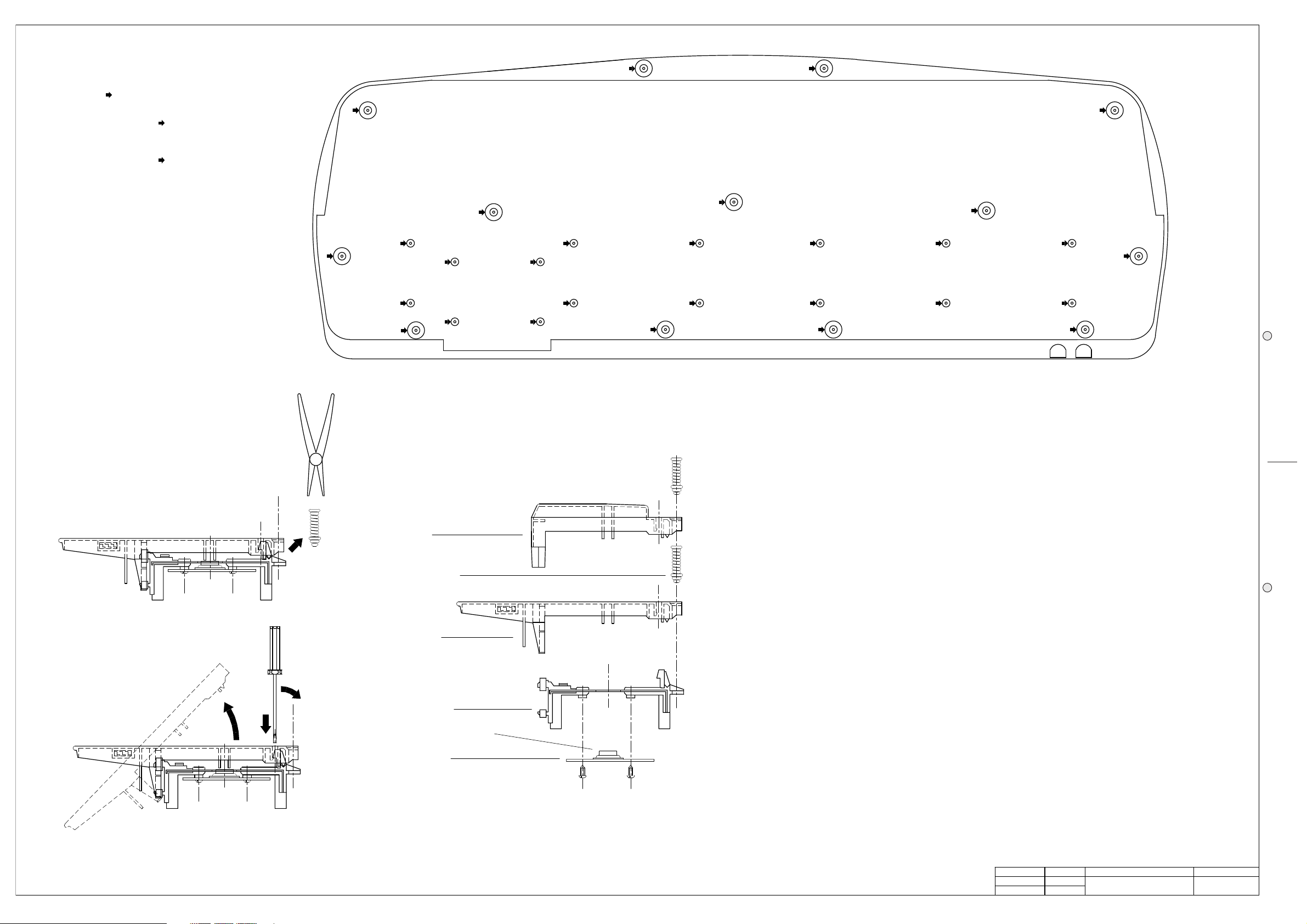
Unlock the key appling not much strenght
Note: To remove a sharp key before
you must remove a near natural key.
3
Remove the key return spring
Dual Contact Rubber Strip
Contact board
2
1
Keyboard Base
Natural Key
Key Return Spring
Sharp Key
Keyboard Disassembling Instructions
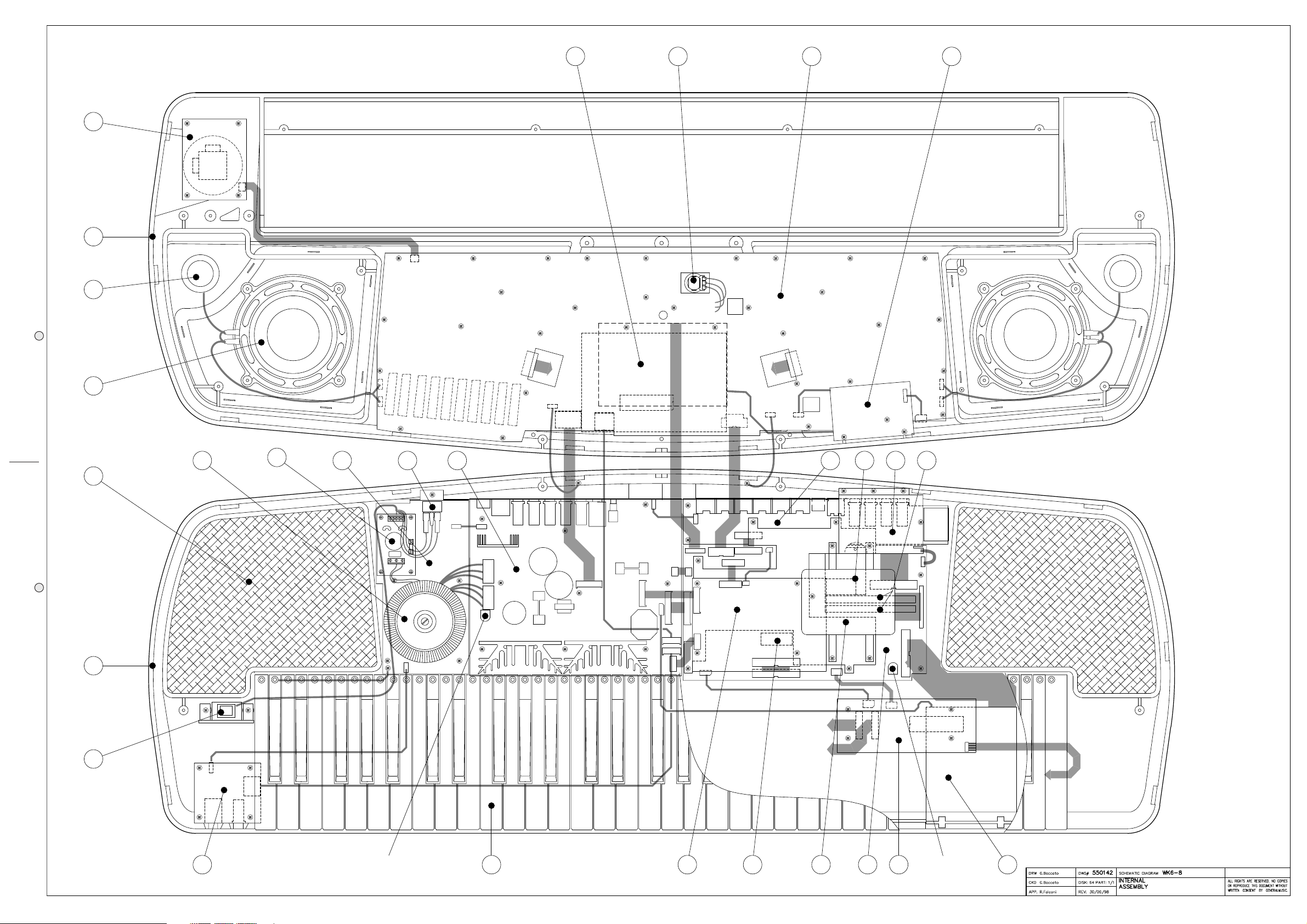
To access to the Disk Drive
remove the screws marked by
Opening Instructions
refer to fig. 1
remove the screws marked by
To separate the keyboard from chassis
screws marked by
To open the instrument remove the
(open the instrument before proceed)
D
K
Keyboard Exploded View
D
K
D
K
D
D
K
K
Fig. 1
K
K
K
K
K
K
K
K
Autotest Procedure
(these instructions execute a final test to be performed after a repairing)
1. LCD Contrast
Set the better LCD display contrast adjusting the VR1 trimmer on Power Amplifier & Supply Board, check the contrast
excursion by the potentiometer on controls panel.
2. After Touch
Set the After Touch adjusting the VR1 trimmer on Cpu & Sound Generator Board (a more accurate method is described
on Adjustment Table), check it’s action along all the keyboard extension.
3. Serial Connection and Date/Time set
Press GENERAL and go to page 3 using the page scroll keys, select COMPUTER with the cursor keys and press
MODE (F8), select MACINTOSH using the cursor keys, press ENTER.
Go to page 4 and press the SET DATE (F1) button, set the day, month and year using the DIAL or the numeric keypad,
press ENTER; also set the time pressing SET TIME (F2) finally return to the first page of GENERAL settings.
Verify the RS422 function checking the 1MHz clock signal on pin 1 of COMPUTER socket.
4. Controls Panel
Press in order GENERAL, SYSTEM INFO (F2) and F8 to enter in the TEST page, confirm the operation pressing
ENTER, select PANEL TEST (A) and subsequently push all the buttons on the control panel to check their correct
operation, verify the TRACKBALL joystick operation checking its value variation from 0 to 127, with 64 at the center, for
PITCH BENDER action and 0 to 127 value variation, with 0 at the center, for MODULATION action.
Press simultaneously ENTER and ESCAPE to return at the Test page.
5. Hardware TEST
Install, if you haven’t already installed, all the optional accessories: Backed DRAM, SIMM DRAM, HARD DISK, A/V or
A/V with Vocal Processor,
From the Test page press ALL PART (F1) to test all the hardware functions, note: to test the diskette you must have
inserted a new diskette in the drive.
Press HARDWARE SET a sinus tone must be heard, press EFFECT BYPASS to deactivate the dsp effects, insert a
jack plug in the headphones socket and measure with the oscilloscope 5Vpp on its output.
Insert a microphone in the MIC/LINE input and check if it operates correctly.
6. Data Backup
Turn off the instrument and wait at least 30 seconds, turn on and press in the following order GENERAL, SYSTEM
INFO (F2), F8, ENTER and DATA HOLD to test if the data is held back.
All test are done and you can remove the more optional accessories you have installed, remember to re-set all the
jumpers if necessary.
APP.
CKD
DRW
REV:
DISK:
DWG#
PRT:
PCB#
GENERALMUSIC S.p.A. ITALY
ALL RIGHTS ARE RESERVED, NO COPIES
WRITTEN CONSENT BY GENERALMUSIC.
OR REPRODUCE THIS DOCUMENT WITHOUT
G. Boccato
G. Boccato
550144
64 1/1
01/07/98
OPENING & KEYBOARD
DISASSEMBLING INSTRUCTIONS
AUTOTEST PROCEDURE