manuals.online logo
Brands
  1. Home
  2. •
  3. Brands
  4. •
  5. Gent
  6. •
  7. Control Panel
  8. •
  9. Gent COMPACT-RPT Owner's manual

Gent COMPACT-RPT Owner's manual

These instructions cover the installation and
operation of the repeat indicator panel.
Installation
a. Open the outer cover
b. Insert the external cable into the backbox
assembly at the required entry point.
c. Mark the fixing points and secure the backbox
to the wall.
d. Connect the cable to terminals.
e. Refit the front cover and flap.
All outstanding work is carried out during the
commissioning of the system.
4188-760 issue 4_01-10_Rept ind. 1
Installation and Operation
Repeat indicator panel
(COMPACT-RPT / SENADV-IND)
PANEL
MASTER CONTROL BOARD
REPEAT RS485
24V B A
0V
P15
Terminals P15 is PORT 0 of
Master Control Board
(Card 0)
The factory default setting of PORT 0
is set for to allow
repeat indicator panel connection
Repeat mode
REPEAT INDICATOR PANEL 1
-
+
a
b
RS485
earth
PANEL
MASTER CONTROL
BOARD
Terminals P15 is PORT 0 of
Master Control Board
(Card 0)
The factory default
setting of PORT 0 is
to allow connection to
repeat indicator panel
Repeat mode
REPEAT RS485
24V BA
0V
P15
REPEAT INDICATOR PANEL 1
a
b
RS485
earth
REPEAT INDICATOR PANEL 4
-
+
24V
a
b
RS485
earth
UP TO 4 REPEAT INDICATOR
PANELS MAXIMUM
POWER
SUPPLY UNIT
+-
If there is only
one repeat indicator
panel connected
then use the 24V
supply on the
Master control board.
-
+
24V
24V
24V
S24
RESET S24
REPEAT INDICATOR PANEL 3
RESET
REPEAT INDICATOR PANEL 2
ON
RESET
REPEAT INDICATOR PANEL 1
ON
RESET
REPEAT INDICATOR PANEL 4
ON
12345678
ON
12345678
12345678
12345678
S24
J2 J3 J4
J6 J5 J7
J2 J3 J4
J6 J5 J7
J2 J3 J4
J6 J5 J7
J2 J3 J4
J6 J5 J7
END STATION LINK SETTING
ON
S24
ON
ON
ON
9600 baud
4800 baud
2400 baud
1200 baud
12
SWITCH
POSITIONS
S24
1&2
123
456
789
0
+
REL
-
24V
a
b
RS485
ON
12345678
J6 J5 J7
Back cable entry point
Thinned sections
on sides of enclosure for
cable entry 4 enclosure fixing points
Controls and indications
Typical System Events
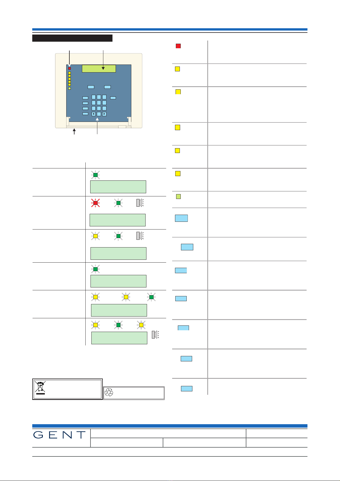
Indicators
Installation and Operation Repeat indicator panel
Gent by Honeywell reserves the right to revise this publication from time to time and make changes to the content hereof without
obligation to notify any person of such revisions of changes.
Hamilton Industrial Park, Waterside Road, Leicester LE5 1TN, UK Website: www.gent.co.uk
Telephone: +44 (0) 116 246 2000 Tech. Support: www.gentexpert.co.uk Fax (UK): +44 (0)116 246 2300
2 4188-760 issue 4_01-10_Rept ind.
by Honeywell
Am Ende des Einsatzes des Produkts, muss das
Produkt, die Verpackung, die Batterien, usw. einer
fachgerechten Entsorgung bzw. einem fachgerechten
Recyclings zugeführt werden, in Einklang mit den
nationalen und regionalen Vorschriften.
Do not dispose of with your normal household waste.
Do not burn.
WEEE Directive:
At the end of their useful life, the packaging,
product and batteries should be
disposed of via a suitable recycling centre.
With the fire system
healthy only the power
light is lit at the repeat
indicator panel.
When a loop device is
operated a fire indication is
given at the repeat
indicator panel.
When a device is removed
from a loop circuit, a fault
indication is given at the
repeat indicator.
When a removed device is
replaced the display gives
a replaced message.
Fire
Panel
buzzer
Fault
Panel
buzzer
When a sector is disabled
the repeat indicator gives a
sounder disabled
indication.
Disablement Sounder
When the mains power to
the main control panel has
failed the repeat indicator
gives corresponding
indication.
Fault
Panel
buzzer
Power Power Fault
Power
Power
Power
Power
Power
Visual and audible indicationsEvents Description
Fire 1:MCP;Number 1
on Loop 1
Lost device
Number 5 on Loop 1
Device Replaced
Number 5 on Loop 1
Sector Disabled
Card 1
Mains failed
Repeat panel
123
456
789
0
Fire
Fault
System Fault
Disablement
Sounder
Power Fault
Power
Test Cancel Buzzer
Fire
Fault
Disablement
Warning
Display Mode
Message display
Indicators
Controls
Cover open
This light is illuminated when at least
one fire event has been detected in
the system.
This light is illuminated when part of
the fire alarm system has been
disabled.
This light is illuminated always with
either the FAULT light or the
DISABLEMENT light to indicate there
is a sounder fault or sounder
disablement.
This light is illuminated when at least
one fault event has been detected in
the system.
This light is illuminated when there is
a fault with the system processor or
communication has failed.
This light is illuminated to indicate
mains or battery supply failure on the
panel.
This light is illuminated to indicate the
panels mains power is present.
Pressing this button will cause all the
lights and display to illuminate and
cause the local buzzer to sound for
approximately 2 seconds.
Pressing the Cancel Buzzer button.
This operating will also cancel the
Control panel buzzer.
This button calls up the FIRE event
messages. The individual messages
can be retrieved by pressing the
buttons .
This button calls up the FAULT event
messages. The individual messages
can be retrieved by pressing the
buttons .
This button calls up the WARNING
event messages. The individual
messages can be retrieved by
pressing the buttons.
This button calls up the
DISABLEMENT event messages. The
individual messages can be retrieved
by pressing the buttons .
Not used at present.
Fire
Disablement
Sounder
Fault
System Fault
Power Fault
Power
Test
Cancel Buzzer
Fire
Fault
Warning
Disablement
Display Mode

This manual suits for next models

1

Other Gent Control Panel manuals

Gent Xenex1 Product guide

Gent

Gent Xenex1 Product guide

Gent Nano User manual

Gent

Gent Nano User manual

Popular Control Panel manuals by other brands

CLARCOR UAS DPM owner's manual

CLARCOR

CLARCOR UAS DPM owner's manual

Gilson HM-630 operating manual

Gilson

Gilson HM-630 operating manual

Halma SENSITRON MULTISCAN++ PK-32 manual

Halma

Halma SENSITRON MULTISCAN++ PK-32 manual

FunkTronic Major BOS 4VD manual

FunkTronic

FunkTronic Major BOS 4VD manual

Crowcon Gasmaster 1 Installation, commissioning and maintenance instructions

Crowcon

Crowcon Gasmaster 1 Installation, commissioning and maintenance instructions

RIB KS2 Assembly instructions

RIB

RIB KS2 Assembly instructions

HUBBELL LIGHTING CX quick start

HUBBELL LIGHTING

HUBBELL LIGHTING CX quick start

Notifier AFC-600 installation manual

Notifier

Notifier AFC-600 installation manual

Controls MVP-62350 product manual

Controls

Controls MVP-62350 product manual

Potter PFC-100RC Installation, operation and instruction manual

Potter

Potter PFC-100RC Installation, operation and instruction manual

drexel und weiss aerosilent topo Operating, Maintenance, Commissioning

drexel und weiss

drexel und weiss aerosilent topo Operating, Maintenance, Commissioning

Savant ITP-E5500 Quick reference guide

Savant

Savant ITP-E5500 Quick reference guide

Balboa GL Series Quick reference guide

Balboa

Balboa GL Series Quick reference guide

BLAUBERG Ventilatoren S25 user manual

BLAUBERG Ventilatoren

BLAUBERG Ventilatoren S25 user manual

LinkAYL LK-UP24 Series quick start guide

LinkAYL

LinkAYL LK-UP24 Series quick start guide

LinkAYL LK-CP63 Series quick start guide

LinkAYL

LinkAYL LK-CP63 Series quick start guide

Fike FIK-RA100BD Product installation document

Fike

Fike FIK-RA100BD Product installation document

Bosch Solution Ultima 880 Quick reference guide

Bosch

Bosch Solution Ultima 880 Quick reference guide

manuals.online logo
manuals.online logoBrands
  • About & Mission
  • Contact us
  • Privacy Policy
  • Terms and Conditions

Copyright 2025 Manuals.Online. All Rights Reserved.