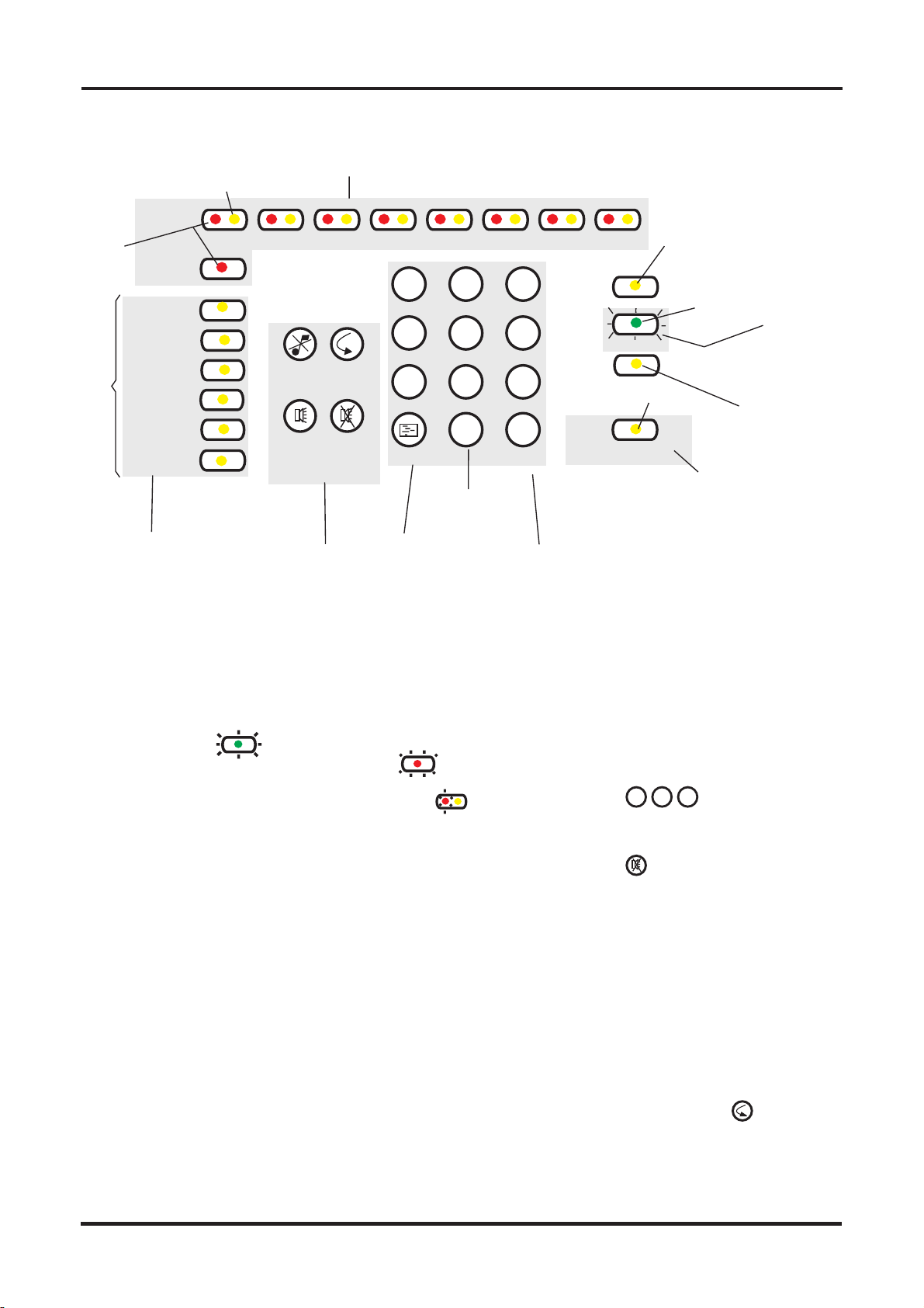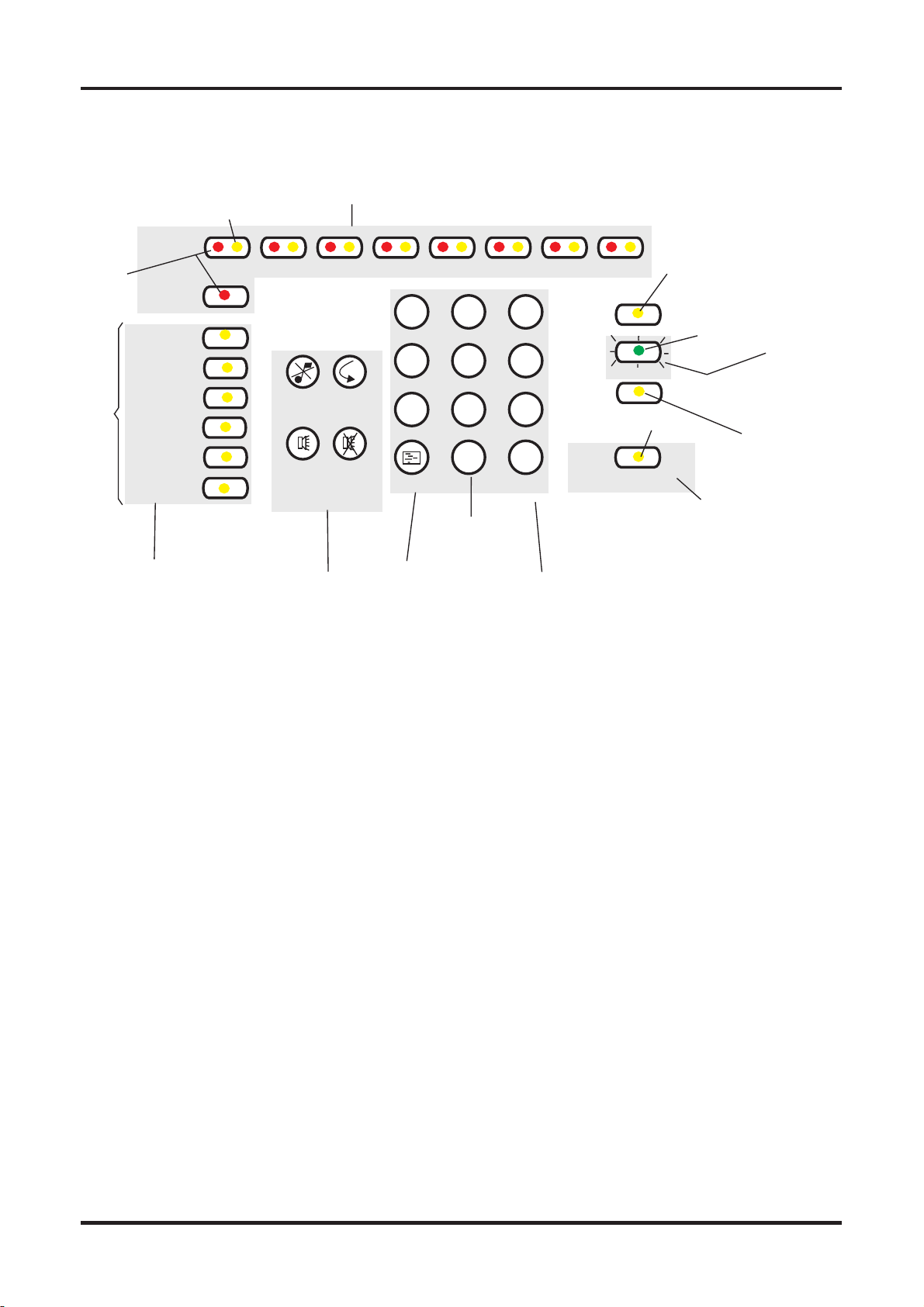
Description of main
controls and
indicators
Controls (Only available when
access code is entered)
qNumeric keypad. Allows the
entry of numeric data, ie pass-
words, addresses, data, etc.
qShift key. The shift key gives
access to the main functions of
the panel.
qDisplay test key. Pressing the
Display Test key after entering
access code#(*) will initiate a
sequence which illuminates all
the indicators in turn enabling
the indicators to be checked.
#Coded entry is only
required if Cancel Buzzer or
Display test functions are
configured for operation at
Access level 2.
qCancel Buzzer. Pressing the
Cancel Buzzer button after en-
tering access code#(*) will stop
the internal buzzer sounding.
qSystem Reset. The system re-
set key when pressed after en-
tering access code(*) will return
the system to its normal operat-
ing state. If there are uncleared
fires or faults then these condi-
tions will re-occur.
qSound Alarms. Pressing the
Sound Alarms button after en-
tering access code(*) will sound
all of the system alarms. Should
only be pressed in an emer-
gency or at other agreed times,
ie sounder tests.
qSilence Alarms. Pressing the
Silence Alarms button after en-
tering access code(*) will si-
lence the system alarms.
Should only be pressed when
the emergency is over.
*Three digit code.
Indicators.
qFire. When lit indicates that the
system has detected a fire.
qFault. When lit or flashing indi-
cates that there is a fault condi-
tion on the system which
requires rectification.
qZoneFire/Fault/Disablement.
Indicates when there is a fire
(red indicator lit or flashing) or a
fault (yellow indicator flashing)
on the zone applicable to the in-
dicators. A lit yellow indicator in
conjunction with other indicators
is used to indicate various dis-
abled conditions.
qSystem Fault. This indicator
when lit indicates that there is a
fault in the panel’s processor.
qPower Fault. When lit or flash-
ing indicates that there is a
power supply fault present.
qEarth Fault. This indicator
when lit or flashing indicates
that there is an Earth Fault on
the system.
qSounder Fault. When flashing
in conjunction with a flashing
fault indicator indicates a
sounder fault. When lit in con-
junction with the disabled indi-
cator indicates that the
sounders are disabled.
qDisabled. Indicates in conjunc-
tion with the sounder or the
zone indicators a disabled con-
dition.
qTest. When lit indicates that the
panel is in Test mode.
qPower. When lit indicates that
the panel is powered up.
qDay/Night. When lit this indi-
cates that Day Mode has been
enabled. Night Mode is indi-
cated by the indicator being un-
lit.
qAccess/Function. The Ac-
cess/Function lamp will flash
when the shift key is pressed
and be lit when the coded func-
tions are accessed.
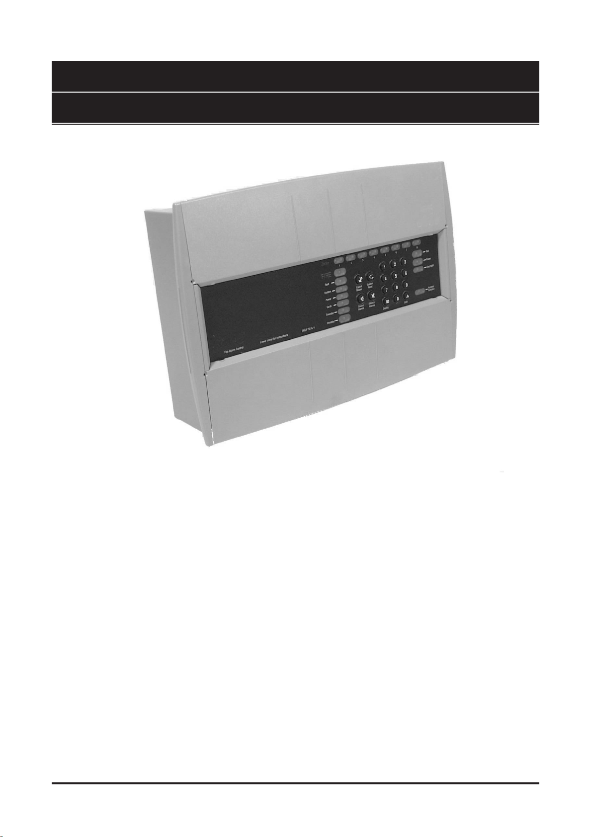
Description of main controls and indicators Fire Panels
03/01 2 Part 2 of 4188-424 Issue 2
Cancel
Buzzer System
Reset
Sound
Alarms Silence
Alarms
123
456
789
0
v
Shift or Function
key
Shift
Numeric
keypad
Display test
key
Display
Essential controls
Zones
FIRE
Fault
System
Power
Earth
Sounder
Disabled
Test
Day/Night
Access /
Function
Normally lit
to indicate
Power supply
healthy
The light is lit when
the Function key is pressed
or there is an entry to control
with coded access
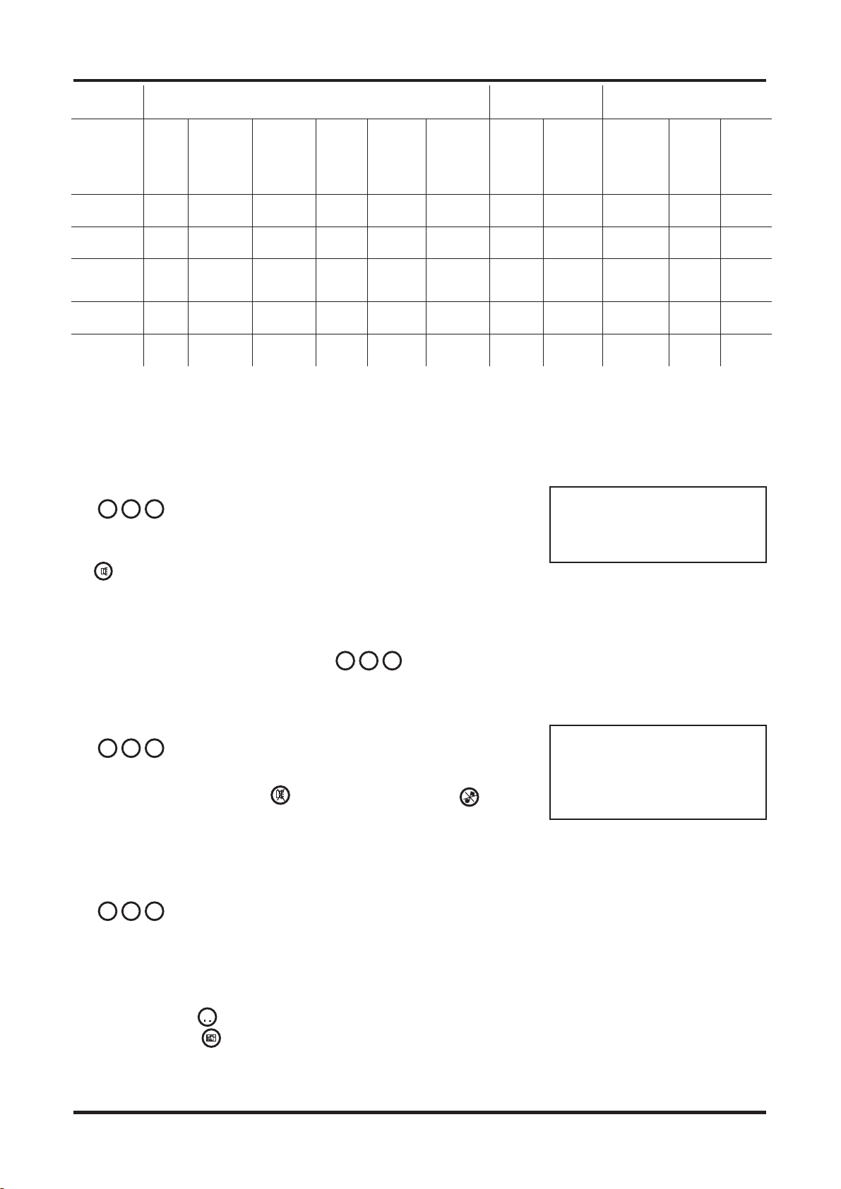
ZONE Fire, Fault or Disablement indications
Other Fault
indications
1red
yellow
2 3 4 5 6 7
yellow
yellow
yellow
green
8
Power
yellow
Figure 1 Controls and indications
cd8m191
http://www.firealarmengineers.com