6
C
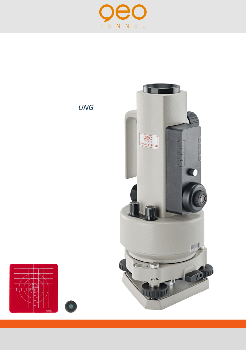
GERÄT EINSCHALTEN
BEACHTE
Beim Einschalten des Laserstrahls zur Decke
unbedingt Filter aufsetzen.
Schalter AN/AUS Laserstrahl zur Decke
und / oder AN/AUS Laserstrahl zum Boden
bis zum Klick nach rechts drehen. Der
Laserstrahl ist nun eingeschaltet. Um die
Intensität des Laserstrahls zu verstärken,
Knopf weiter nach rechts drehen. Knopf
wieder nach links bis zum Klick drehen, um
Laserstrahl wieder auszuschalten.
Der Laserstrahl ist bei Tageslicht bis ca.
120 m und bei dunkleren Bedingungen
bis ca. 250 m sichtbar. Über diese Entfer-
nungen hinaus kann das Gerät optisch - also
über Fadenkreuz und Zieltafel - eingesetzt
werden.
POWER ON/OFF
N.B.
When using the zenith laser it is essential
the filter is used at all times.
To Power-On the zenith laser and centring
laser rotate the switches clockwise until
you hear a “click“. The laser beams are
now switched on and any further clockwise
rotation will increase the intensity of the
laser beams.
To Power-Off the laser beams rotate the
switches anti-clockwise until you hear a
“click”.
The visible distance of the zenith laser beam
is up to 120 m in daylight conditions and
250m in dark conditions.
For all measurements exceeding these
distances the instrument must be used
optically.
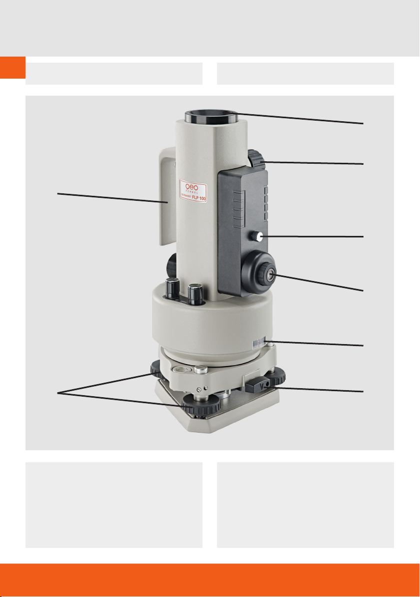
BEDIENUNG
Gerät aufstellen
Gerät direkt auf dem Boden aufstellen oder
auf dem Stativ befestigen.
Gerät möglichst waagerecht aufstellen und
die Dosenlibelle mit Hilfe der Fußschrauben
des Dreifußes zentrieren.
Röhrenlibelle mit Hilfe der Fußschrauben
exakt zentrieren. Dabei Gerät jeweils um
90°, 180° und 270° drehen und Einstel-
lung der Röhrenlibelle überprüfen und ggf.
korrigieren.
Nur wenn beide Libellen exakt eingestellt
sind, kann das Gerät genau arbeiten.
OPERATION
Set up instrument
Position the instrument on a solid stable
surface or a suitable tripod.
With the instrument as upright as possible
use the footscrews to centralise the circular
level.
Rotate the instrument until the plate level is
parallel to a line between two footscrews.
Centre the plate level by using the same
two footscrews. Rotate the instrument by
90°and centre the plate level once more
using the third footscrew. Repeat this
procedure until the plate level is perfectly
centred in all positions.
Optimum precision can only be achieved
when the instrument is perfectly level.