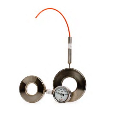
Geosense VW PIEZOMETERS User manual

Version 1.4 May 09
I
N
S
T
R
U
C
T
I
O
N
M
A
N
U
A
L
VW PIEZOMETERS

2
Version 1.4 May 09
CONTENTS
1.0 INTRODUCTION Page 3
1.1 Applications
1.2 Theory of operation
2.0 CONFORMITY Page 6
3.0 MARKINGS Page 7
4.0DELIVERY Page8
4.1 Packaging
4.2 Handling
4.3 Inspection
4.4 Storage
5.0 INSTALLATION Page 10
5.1 Zero Pressure or Base Readings
5.2 Preparation for installation
5.3 Installation Procedures - Boreholes
5.4 Installation Procedures - Trenches & Pockets
5.5 Installation Procedures - Observation Wells or
as Water Level Sensor
5.6 Grouting
6.0 DATA HANDLING Page 33
6.1 Taking readings
6.2 Data reduction
7.0 MAINTENANCE Page39
8.0 TROUBLESHOOTING Page 39
9.0 SPECIFICATION Page 41
10.0 SPARE PARTS Page 42
11.0 RETURN OF GOODS Page 43
12.0 LIMITED WARRANTY Page44
13.0 APPENDIX Page45

3
Version 1.4 May 09
It is VITAL that personnel responsible for the
installation and use of the piezometers READ and
UNDERSTAND the manual, prior to working with the
equipment.
1.1 General Description
The Vibrating Wire Piezometer is an environmentally sealed sensor that is used to
register changes in fluid pressure, generally in, but not limited to, under ground
locations.
A Vibrating Wire Piezometer can be installed or included in many types of monitoring
regime and can be linked to various types of readout equipment.
The primary uses for piezometers are :-
Soil and rock pore pressure measurement.
Water level monitoring ( groundwater or open chambers )
With applications such as, but not limited to, the following :-
Embankment stability and safety monitoring
Measuring loads behind retaining walls
Assessing soil consolidation
Measurement of uplift pressures acting on structural foundations
Verification of seepage patterns and models
Slope stability monitoring
Water level monitoring for Environmental control
Tidal influence assessment
Pump Testing
Particular features of the MGS-Geosense piezometer are:-
Reliable long term performance.
Rugged; suitable for demanding environments.
High accuracy.
Insensitive to long cable lengths.
The Piezometer is based upon ‘industry standard’ Vibrating Wire technology. When
electronically excited, the sensor produces an output signal in the form of an
alternating current. The frequency of the alternating current can then be readily
converted to a fluid pressure by applying individual calibration factors.
(Continued on page 4)
1.0 INTRODUCTION
This manual is intended for all users of Vibrating Wire Piezometers manufactured by
MGS Geosense and provides information on their installation, operation and
maintenance.

4
Version 1.4 May 09
Frequency signals are particularly suitable for the demanding environment of civil
engineering applications, since the signals are capable of long transmission distances
without degradation. They are also somewhat tolerant of damp wiring conditions and
resistant to interference from external electrical noise.
The MGS-Geosense range of VW piezometers is supplied in various configurations to
suit varying installation environments and techniques. Each VW piezometer is fitted
with a length of connecting cable, an internal temperature sensor and a surge
arrestor. Each VW piezometer option is detailed in this manual, with its own specific
installation instructions.
(Continued from page 3)

5
Version 1.4 May 09
1.2 Theory of Operation
The Vibrating Wire Piezometer consists of a tensioned steel wire, anchored at one
end to a flexible diaphragm ( the sensing element ) and at the other end to the
Nimonic inner body, all sealed into a stainless steel body. The internal parts of all
MGS Geosense piezometers are identical, only the thickness of the diaphragm and
the geometry of the body changes.
Two opposing coils are located within the inner Nimonic body close to the axis of the
wire. When a brief voltage excitation, or swept frequency excitation is applied to the
coils, a magnetic field is induced causing the wire to oscillate at its’ resonant
frequency. The wire continues to oscillate for a short period through the ‘field’ of the
permanent magnet, thus generating an alternating current (sinusoidal) output. The
frequency of this current output is detected and processed by a vibrating wire readout
unit, or by a data logger equipped with a vibrating wire interface, where it can be
converted into ‘Engineering’ units of pressure.
As fluid pressure is applied to the exposed side of the flexible diaphragm, the
diaphragm deflects, causing a change in the tension of the wire behind it. The change
in tension of the wire results in a change in resonant frequency of oscillation of the
wire, with the square of frequency of oscillation being directly proportional to the
applied pressure.
For further information see Section 6 - Data Handling.

6
Version 1.4 May 09
2.0 CONFORMITY
Marton Geotechnical Services Ltd
Geotechnical Centre
Rougham Industrial Estate
Rougham, Bury St Edmunds
Declaration of Conformity
Document Number QF037 (Iss 2)
We Marton Geotechnical Services Ltd at above address declare under our sole responsibility that the
Geosense products detailed below to which this declaration relates complies with protection requirements
of the following harmonized EU Directives,
Low Voltage Directive 73/23/EEC (as amended by 93/68/EEC)
The Electromagnetic Compatibility Directive 2004/108/EC
The Construction Products Directive 89/106/EEC
Equipment description Vibrating Wire Piezometers
Make/Brand Geosense
Model Numbers VWP-3000, VWP-3001, VWP-3101, VWP-3200
VWP3201, VWP-3300, VWP-3400
This equipment has been designed and manufactured with reference to the following standards:
All mechanical drawings used in the production of this equipment are based upon BS 8888
Electrical/electronic drawings are based upon BS 3939.
A technical file for this equipment is retained at the above address
This Declaration of Conformity was prepared according to EN ISO/IEC 17050-1:2004.
Martin Clegg
Director

7
Version 1.4 May 09
3.0 MARKINGS
Geosense piezometers are labelled with the following information:-
Manufacturers name & address
Product type
Model
Serial number
CE mark

8
Version 1.4 May 09
4.3 Inspection
It is important to check all the equipment in the
shipment as soon as possible after taking delivery
and well before installation is to be carried out.
Check that all the components detailed on the
documents are included in the shipment. Check
that the equipment has not been physically
damaged.
ALL Geosense VW piezometers carry a unique
identification serial number which is located on the
cable close to the piezometer body and at the free
end of the cable ( see right ). All VW piezometers
are supplied with individual calibration sheets that
include their serial numbers and these will shipped
with the piezometers.
Calibration Sheets contain VITAL information about the
piezometer. They MUST be stored in a safe place. Only
(Continued on page 9)
4.0 DELIVERY
This section should be read by all users of Vibrating Wire
Piezometers manufactured by MGS Geosense.
4.2 Handling
Whilst they are a robust devices, VW piezometers are precision measuring
instruments. They and their associated equipment should always be handled with
care during transportation, storage and installation.
Once the shipment has been inspected ( see below ), it is recommended that
piezometers remain in their original packaging for storage or transportation.
Cable should also be handled with care. Do not allow it to be damaged by sharp
edges, rocks for example, and do not exert force on the cable as this my damage the
internal conductors and could render the installation useless.
4.1 Packaging
VW Piezometers are packed for transportation to site. Packaging is suitably robust to
allow normal handling by transportation companies. Inappropriate handling
techniques may cause damage to the packaging and the enclosed equipment. The
packaging should be carefully inspected upon delivery and any damage MUST be
reported to both the transportation company and MGS Geosense.

9
Version 1.4 May 09
4.4 Storage
All equipment should be stored in an environment that is protected from direct
sunlight. It is recommended that cables be stored in a dry environment to prevent
moisture migrating along inside them in the event of prolonged submersion of
exposed conductors.
During operational checks and establishing zero values, it will be necessary to
submerge the VW piezometers. Subsequent exposure to sub-zero temperatures
(Continued on page 10)
copies should be taken to site.
CHECK the piezometer ‘Zero Readings’
against the factory ‘Zero Readings’ on
arrival to ensure they have not changed
due to damage during transportation. To
do this, connect a Vibrating Wire readout to
the bare cable ends (Black and Red
conductors). – See readout manual for
connection guidance.
*NB If the readout display is in
‘Period’ units ( eg 0.03612 ) a
calculation must be performed to
convert to Hz2/1000 ( Linear Digits )
units, since the calibration sheet is
presented in Hz2/1000 units. The
Geosense Readout model VW200
displays the readings in ‘Period’. The
RST readout / logger unit Model
Number VW2106 displays the readings
in Linear digits. See Section 6 of this
manual for more information on units
and conversion routines.
Prior to carrying out a ‘Zero Reading’
CHECK, ensure that the piezometers have
been stored in a reasonably stable
temperature for at least 30– 60 minutes.
Record the values displayed on the readout ( and units ) against the piezometer
serial numbers. If these ‘out of the box’ CHECK readings show significant differences
( +/- 40 digits ) to the zero pressure values on the calibration sheets, contact MGS
Geosense for assistance. ( It should be noted that the ‘CHECK Readings WILL be
affected by the atmospheric pressure & altitude ).
If components are missing or damaged, contact the delivery company, the supplier
and / or MGS Geosense.
(Continued from page 8)

10
Version 1.4 May 09
may cause damage to the diaphragms if the water they contain is allowed to freeze.
Storage areas should be free from rodents as they have been known to damage
connecting cables.
No other special requirements are needed for medium or long-term storage although
temperature limits should be considered when storing or transporting associated
components, such as readout equipment.

11
Version 1.4 May 09
It is VITAL that personnel responsible for the installation and
use of the piezometers READ and UNDERSTAND the manual,
prior to working with the equipment.
**********
As stated before, it is vital to check all the equipment in the shipment soon after
taking delivery and well before installation is to be carried out. Check that all
components that are detailed on the shipping documents are included.
5.0 INSTALLATION
This section of the manual is intended for all users of Vibrating Wire Piezometers
manufactured by MGS Geosense and is intended to provide guidance with respect to
their installation.
It must be remembered that no two installations will be the same and it is inevitable
that some ‘fine tuning’ of the following procedures will be required to suit specific site
conditions.
5.1 ZERO Pressure or BASE Readings
Vibrating wire transducers differ from most other pressure sensors in that they
indicate a reading with no pressure applied. ZERO or BASE Readings can vary
significantly between sensors.
It is, therefore, ESSENTIAL TO TAKE BASE READINGS
BEFORE
INSTALLATION.
As with all transducers, do not directly handle the piezometer body when recording
the base readings, as this will cause local temperature gradients across the
piezometer that will distort the readings.
Where piezometers are to be installed with their bodies orientated either horizontally
or with their filters upwards, read the base readings in a similar orientation. ( Low
pressure transducers, in particular, can be very sensitive to orientation. Always
obtain base readings with the sensor orientated in the same direction in which it will
finally be installed.

12
Version 1.4 May 09
The ‘on-site’ BASE readings for the Vibrating Wire
Piezometer should be obtained as follows:
1. Fill a large bucket with clean, potable water,
ideally of a temperature close to that of the
groundwaterr temperature.
2. Ensure that the bucket is away from any heat
sources and shaded from the sun. Stir the water
occasionally to ensure an even temperature.
Place the piezometer body in the bucket.
3. With the transducer submerged in the water,
carefully remove the rubber sleeve from the
piezometer.
4. With the transducer still submerged in the
water, carefully remove the filter from the
piezometer body by carefully twisting and
pulling it, leaving both submerged in the water.
5. At the free end of the cable, connect the red
and black leads to a vibrating wire readout unit
and occasionally monitor the transducer output
by turning on the readout and observing the
display ( see the readout user manual for
assistance ). After 10 or 20 readings, be sure
to turn off the readout or disconnect the wire so
as to avoid ‘heating’ the Vibrating Wire element.
6. Leave the transducer completely submerged in
water for a minimum of 30-60 minutes and until
the output of the transducer is unchanged over
a period of 2-5 minutes.

13
Version 1.4 May 09
7. Turn on the readout. Holding the piezometer
cable, lift the transducer out of the bucket,
allowing it to hang vertically downwards and
immediately record 2 or 3 readings. Replace the
transducer in the water as before. After one
minute of immersion, repeat and record another
set of readings. Repeat three times, checking
that the readings displayed are within +/- 0.5
digits of each other.
8. Record these readings together with the date
and time.
9. Return the transducer to the water with the
open end upwards, but submersed.
10. Obtain and record the barometric
( atmospheric ) pressure for future use. It is
best to use a site based reading but a local
metrological station may be used.
11. Locate the filter in the base of the bucket and
having ensured that the void in the filter housing
is completely filled with water, replace it onto
the piezometer body.
12. Take great care with HAE ( High resistance to
Air Entry ) filters. Allow the water pressure to
dissipate through the filter by only applying a
small amount of pressure to the filter body,
leaving time for the water to pass through it.
(Continued from page 12)
(Continued on page 14)

14
Version 1.4 May 09
13. Store the piezometer in water until ready for
installation ( or repeat the above just prior to
installation )
(Continued from page 13)

15
Version 1.4 May 09
5.2 Preparation for Installation
Prior to installation of a piezometer it is essential to establish and confirm details of
the installation to be carried out. Some of the main considerations are listed below :-
1. Intended elevation and depth to Piezometer?
This can be calculated as either the depth below a known level ( ground level
for example ) or as the elevation with respect to a remote datum. For borehole
installations the final depth should be calculated and then the cable marked to
show the intended installed position.
For surface installations, a reference elevation can be created close to the final
position of the piezometer.
2. Borehole Installation type / Specification
Where a piezometer is to be installed in a borehole, is it to be pushed into the
base of the borehole, installed in a filter pocket, grouted into the borehole
without a filter or provided with a long filter for groundwater monitoring?
The most common type of piezometer installation is the filter pocket type where
the piezometer is used to register pressures from a specific sub-surface horizon
or strata.
The full length ( or observation well ) installation is probably the next most
common. It simply allows groundwater from any horizon to flow into the
borehole to be registered by the piezometer.
Where a rapid response is required from a saturated material with a low
permeability, the piezometer can be pushed into the undisturbed base of the
borehole to provide an intimate connection to the pore water pressure in a
particular horizon.
Some engineers consider that a fully grouted borehole ( using a Bentonite /
Cement mixture ) will allow the piezometer to detect and reflect the pore
pressure equally well. In this installation, the piezometer ( or string of
piezometers ) is suspended in the borehole and the borehole is backfilled with
liquid grout from the base upwards. In some respects, this could be considered
similar to the push-in type installation, where the grout mix reflects the
permeability of the surrounding strata. This approach is particularly
advantageous where more than one piezometer is to be installed in a single
borehole.
3. Surface Installation type / Specification
Where a piezometer is to be installed at surface level, is it to be pushed into a
pre-formed cylindrical pocket or installed in a small excavated pocket? ( These
installations would normally be covered by fill material and often compacted
(Continued on page 16)

16
Version 1.4 May 09
mechanically ).
In a location where high permeability material is present, a sand pocket type
installation is preferred. Where a piezometer is to be installed in a material with
a low permeability, it is normally better pushed into a pre-formed pocket to
maintain intimate contact with the surrounding material. ( Sand pockets should
be avoided in low permeability surface installations, so as to reduce the
presence of trapped air and therefore maintain an acceptable response time ).
4. Filter zone
A specially graded sand ( commonly 600 - 1200 µm ) is the most common
material used to provide a filter and borehole support for the piezometer tip.
The volume of material required will depend upon the borehole diameter and
the length of the filter zone to be formed. Typically a 1 metre zone is
recommended or in accordance with project specifications.
(In some cases piezometers can be fitted inside small hessian bags that are
then filled with filter sand. This creates a pre-formed filter pocket and adds
weight to the assembly to help with borehole installation. The filter bag should
be fitted in advance of installation, filled with sand and allowed to soak in a
bucket of water prior to placing.)
5. Bentonite seal
Where a sealed pocket is to be formed for the piezometer, compressed and
dehydrated Bentonite in the form of either pellets, balls, chips, etc is commonly
used to form the seal. These are commercially available in bagged form or can
be created on site using Bentonite powder and manual labour. ( Man-made
balls are only suitable for shallow boreholes with a diameter ≥100mm. This is
because they are more difficult to use as they can break-up before reaching
their intended elevation in deep boreholes ).
Once in place, the Bentonite expands by absorbing water to form an
impermeable borehole plug. In dry boreholes, water must be added to allow the
Bentonite to swell. Normally a plug is only required above any filter pocket but a
plug may also be used below a pocket, for example, where the borehole
extends beyond a piezometer filter base elevation.
6. Cable marking.
Cables should be marked with unique identification. Markings should be
repeated at regular intervals along the cable where multiple cables are to be
grouped together, so that in the event of cable damage, there may be a chance
that the identification could be exposed and the cables re-joined. Multiple cable
marks are particularly important close to the end of the cable. The spacing of
markings can vary according to specific site requirements but a guide of 5m to
(Continued from page 15)
(Continued on page 17)

17
Version 1.4 May 09
10m is commonly applied (available on request).
7. Tools.
Obtain any tools necessary to carry out the installation. The following is a brief
list of tools typically used during the installation of Vibrating Wire Piezometers.
• Fibre measuring tape with a weight added to the end for borehole depth
measurement and cable length measurement.
• Shovel for placing and levelling fill by hand
• Wire cutters and strippers
• Vibrating Wire Readout unit for checking the piezometer function
• Cable Marking system / equipment ( eg coloured PVC Tapes )
• Grout mixing and placing equipment
• PVC tape

18
Version 1.4 May 09
1. Before drilling the hole it is important to
ascertain the depth at which the piezometer is
to be installed. An indication of the ground
conditions may also be helpful.
2. The borehole should be formed to a depth of
approximately 500mm below the intended
elevation of the piezometer tip. If a Bentonite
plug is required at the base of the borehole, it
will have to be drilled further to accommodate
the plug.
3. Before commencement of installation, the depth
of the hole should be re-checked and the
procedure you intend to follow should be
confirmed with the engineer and discussed with
the driller.
4. Confirm that all materials are available ( filter
sand, Bentonite pellets or balls and backfilling
grout ). The piezometer to be installed should
be transported to the borehole locations in a
container of clean water ( see section 5.1.13 ).
(Continued on page 19)
5.3 Installation Procedures - Boreholes
Each piezometer installation is different and requires both common sense and a gen-
eral understanding of the sub-surface conditions. There are many approaches to
piezometer installation and, in addition to these broad installation guidelines, MGS
Geosense are committed to providing technical support to help engineers and techni-
cians tune their procedures to match particular site conditions and requirements.
Boreholes can be flushed with clean water prior to installation operations if excessive
sediment remains in suspension.
Each piezometer is labelled on the cable, however steps should be taken, perhaps
with the aid of coloured tapes, to mark the cable so that there is no confusion over
piezometer identification. This is particularly important for installations where more
than one piezometer is to be installed in one location.
5.3.1Cased boreholes.
When forming a borehole for instrument installation, it is sometimes necessary to use
a temporary steel sleeve or ‘casing’ to hold the hole open during drilling and installa-
tion operations. The following describes a series of steps that could be adopted to
carry out a piezometer installation in such a fully cased borehole. This procedure can
be adapted where boreholes are only partially cased.

19
Version 1.4 May 09
5. Check the drill hole to ensure that the full depth
is clear and free of obstructions and that any
casing can be withdrawn.
6. CHECK BASE READING OF PIEZOMETER.
Where necessary, record a reading from the
piezometer to confirm that it has not been
damaged since establishing the base readings
( see Section 5.1 )
7. Where necessary and possible, fill the borehole
with clean water.
8. If a Bentonite plug is required at the base of the
borehole, pull any temporary casing back so
that it lowest level corresponds to the top of the
intended plug. Slowly drop Bentonite pellets /
balls down the borehole. Be sure not to let the
pellets / balls plug or stick to the inside of the
casing by checking the depth using a weighted
tape. Ensure that the Bentonite level always
remains below the bottom of the casing.
( Feeding pellets / balls in to the borehole too
quickly will result in ‘bridging’ of casing and
make completion of the installation very
difficult ). The top of any base-plug must be
below the intended piezometer installation
elevation.
9. Once the plug has been formed ( where
required ), the casing should be pulled to about
500mm (or in accordance with specification)
above the new base of the borehole ( the
intended piezometer installation elevation ) and
filter sand should be slowly added to fill the
borehole up to the depth at which the
piezometer is to be installed.
(Continued from page 18)
(Continued on page 20)

20
Version 1.4 May 09
10. With the filter securely fitted to the piezometer,
lower it slowly down onto the sand at the base
of the borehole and record another check
reading.
11. If necessary, coil up and feed the piezometer
cable into the casing so that the drilling rig can
be used to retract the casing. Ensure that there
is enough slack cable to prevent the casing
pulling the piezometer back up the borehole.
( This will have to repeated whenever casing is
to be raised or removed. ) When a section of
casing is removed it will have to be slid along
the cable or the cable passed through it.
12. Pull the temporary casing back to the elevation
of the top of the filter and add more clean filter
sand on top of the piezometer. Continually
check the level of the sand using the weighted
tape.
(Continued from page 19)
(Continued on page 21)
Table of contents
Other Geosense Data Logger manuals

Geosense
Geosense VWNPC-3000 User manual

Geosense
Geosense Wi-SOS 100 User manual

Geosense
Geosense GEOLOGGER G8 PLUS User manual

Geosense
Geosense Laser Tilt90 User manual

Geosense
Geosense GEOLOGGER G8 PLUS Setup guide

Geosense
Geosense Geologger Linx User manual

Geosense
Geosense HLC 6000 Series User manual

Geosense
Geosense Geologger Linx User manual

Geosense
Geosense Geologger GL101A-V User manual
Popular Data Logger manuals by other brands

ICP DAS USA
ICP DAS USA DL-300-WF Series quick start

Martin Lishman
Martin Lishman TuberLog Instruction manual and users guide

LogTag
LogTag USRIC-8 quick start guide

Racelogic
Racelogic PerformanceBox quick start guide

XC-Tracer
XC-Tracer Maxx user manual

NexSens Technology
NexSens Technology iSIC-OEM Operation manual