manuals.online logo
Brands
  1. Home
  2. •
  3. Brands
  4. •
  5. GeoSIG
  6. •
  7. Measuring Instrument
  8. •
  9. GeoSIG GMS plus Owner's manual

GeoSIG GMS plus Owner's manual

GMSplus Quick User Manual
User MUST follow all instructions under the
WARNINGS AND SAFETY
section in the user manual !
Foreword
This manual is provided as a brief guideline to give an overview
of the first steps and it is not intended to cover all the different
circumstances. Please check the GMSplus User Manual for
details.
Step 1. Unpacking
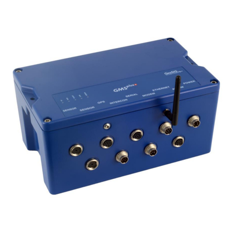
The GMSplus is shipped in a standard packing box containing all
the typical accessories. Some specific options (such as the
external battery) may be supplied in a separate box.
The packing box must be inspected for any external damage and
any damage should be immediately reported to the forwarder.
The contents of the packing box can be checked according to the
order and the packing list. Verify that none of the items have
physical damage. Keep the packing box for transportation to the
final location of the instrument.
Step 2. Installation Organisation
Before proceeding further please revise the figure at the end of
this manual, which illustrates standard and optional connections
of the instrument. This way you can familiarise yourself with the
GMSplus and the options you have received for connectivity.
The following items are required for a typical installation:
• Drill, drill bits, screws and tools for mounting or levelling
• Compass or building references for the axis orientation
• Latest version of GeoDAS software and manual (check
also on our web site www.geosig.com)
• Computer with CD-ROM drive, serial (COM) port and
Ethernet
• Any accessories delivered with the GMSplus (refer also to
the figure at the end of this manual)
We strongly recommend installing GeoDAS (see Step 8) on the
computer prior going to the final installation site. Also it is a good
practice to perform a first test of the entire system in the office in
order to get familiar with it.
Step 3. Site Preparation
The installation site should be selected away from mechanical
and electrical noises and interference sources. The distances
must be evaluated for AC power source, GPS location, phone line
etc.; in order to have sufficient cable lengths.
Make sure that:
• There is AC power near the instrument (either for GMSplus
operation or for the drill during installation).
• If no AC power is present, make sure you have the
required tools for installation accordingly.
• Clean and free space is available on the foundation.
The instrument itself can be mounted in any orientation desired
under the condition that it does not have an internal battery. In
cases where the instrument has an internal battery it must always
be mounted flat on the ground in a non-tilted position.
Step 4. Physical Installation
a
For your convenience a training video explaining the
installation of the GMS-xx and GMSplus is available at
www.geosig.com
à
Support
à
‘How To …’ Videos
The GMSplus has a base plate that must be first fixed to the
ground where the instrument can be mounted on. For this
purpose, the base plate has a central fixing hole (suitable for 8
mm screws) and three levelling screws.
Base plate preparation:
• Mount the 3 levelling screws (D).
• Check that the 4 M6 threads for the instrument fixing are
free from dust.
• Mount the 2 polarization pins on the base plate on the
sides where the connectors will be (E/F).
Drill an 11 mm hole in the concrete with a typical depth of 50 mm
for the supplied M8 concrete anchor (C). Clean the whole area of
dust. Insert the concrete anchor into the hole. Mount the plate in
place and insert the M8 fixing screw (A/B) in its hole. Turn the
plate so it is oriented according to the requirement. Make a
coarse levelling of the plate (D). Start fixing the plate by tightening
the M8 central screw (A). Check regularly the plate orientation
and level till the plate is rigidly fixed (D). Remove the cover of the
instrument and put it on the mounting plate using the 4 screws
and washers to fix it. Take care about the 2 orientation pins on
the plate (E/F).
Step 5. Power Connection
The instrument should be powered from 110 VAC up to 230 VAC,
50 or 60 Hz through the external AC/DC converter or any other
option described at the end of this manual. The power cable is
delivered usually with a suitable plug for the country (e.g. CH, EU,
US). If not usable, the cable can be cut and an appropriate local
power plug has to be purchased locally. The power plug must be
wired by a qualified electrician as:
• Brown or Black wire à Phase
• Blue or White wire à Neutral
It is necessary to connect the M6 earth screw on the base
plate, to the local earth. Make sure the green AC indicator is ON.
Step 6. GPS Connection
The GPS module should be fixed at a location where satellite
signals could easily be received. If the GMSplus is installed inside
a building or a basement, the GPS module should be installed
outside. Once fixed, the GPS can be connected to the GPS
connector.
GS_GMSplus_QuickUserManual_V07.doc / 16.06.2016
Step 7. GMSplus Startup
a
Check the GMS User Manual chapter ‘6. Quick Start up’
for a more detailed step-by-step procedure.
Remove the cover using the four screws on the top corners.
Verify that the battery is correctly fixed and connected to the
system.
User MUST follow all instructions under the
BATTERY (MAINTENANCE) AND SAFETY
section in the user manual !
Let the cover open and connect your computer to the internal
serial port (“CONSOLE”) by using a standard RS-232 patch
cable.
Open any terminal program and chose the appropriate COM port,
baud rate is 115’200.
Switch on the instrument by pressing and holding the POWER
button for 2 seconds. Press <Ctrl> + ‘Z’ as soon the message
appears on the console to enter the test mode. Then Press ‘N’ to
enter and adjust the network settings (Normally it is set to DHCP).
Enter the IP and port of your data server as recovery server. Start
the instrument by pressing ‘5’ in the boot-loader menu.
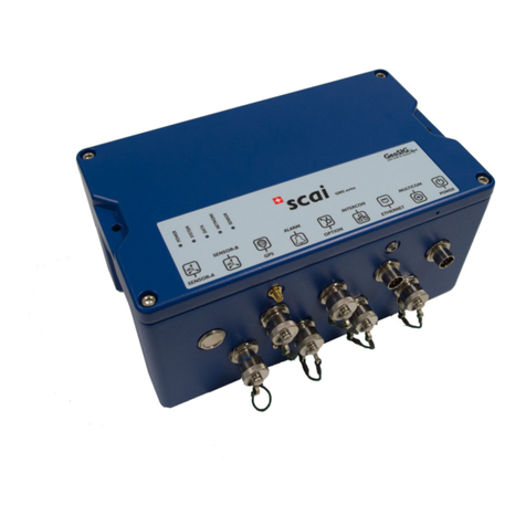
The LED meanings are as follows:
AC (Active Charge) illuminates when external power
input is present at the POWER connector.
RUN flashes when GMSplus is running.
EVENT illuminates during recording and flashes when there
are events recorded in the memory.
LINK flashes to indicate a problem with the connection to
the server and is present during data transfer.
ERROR flashes to indicate a warning condition and flashes
faster to indicate an error condition.
Step 8. Software Installation
To install GeoDAS, a computer running Microsoft Windows™
operating system is needed. Insert the supplied CD in the
computer. GeoSIG CD menu should appear shortly, from which
you can select to install GeoDAS. If not, then launch setup.exe
under the GeoDAS folder on the supplied CD.
Select the Normal mode installation at the prompt and enter the
GeoDAS-DAP code when requested; (applicable if DAP option
has been purchased). If you do not have a DAP code, simply
enter 0 as serial number. In that case, the basic functions will be
operational. You can later purchase and enter a valid DAP code
to unlock the additional functions.
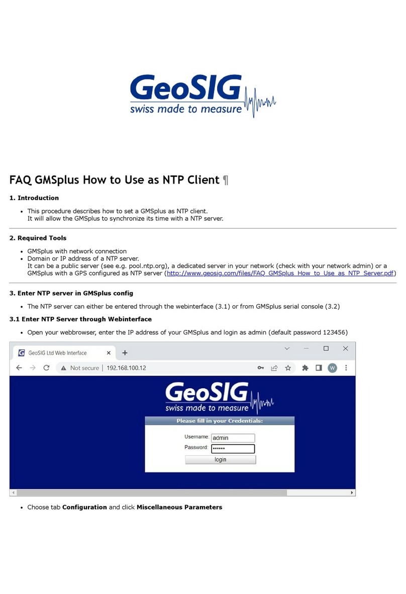
Step 9. First Connection
Once the GMSplus is correctly operating and the GeoDAS is
installed, connect the instrument and the computer to an existing
Ethernet network. Launch GeoDAS, if it’s the first time you launch
GeoDAS, you should have a window asking if you would like to
configure one or more stations, just answer yes and select the
entry “My GMS instrument is connected to the local network”:
Enter the Serial number of the instrument and press Login >
If the instrument and the computer are in the same network the
GMSplus will be found and should appear in GeoDAS. In the
window Stations: General Information make a right click on the
station name of the added instrument and select Instrument
Setup. The Web Interface will open in your default browser.
Login to the Web Interface with the user name admin and the
password 123456
All settings can be done in the Web Interface. At the beginning go
to File Transfer Settings
à
Tick Contact Remote Servers à
Enter the IP of your computer and click Add Server with IP.
Save the configuration by clicking on Save Configuration to
Device.
Now the instrument will periodically connect to your laptop to
upload data or SOH files.
After the instrument has restarted it is ready for operation and can
be configured according to the GMSplus User Manual.
a
Before starting measurements, the GMSplus should be
switched on for 30 minutes to stabilise at the installation
site climate. This is essential to allow the instrument to
adapt and naturalise in the ambient conditions of the site
where the measurements will take place. Failure to follow
this advice may result in a higher offset drift.
a
Further information can be found in the product manuals
under the Manuals folder on digital media or on our
website www.geosig.com.
S
E
N
S
O
R
S
E
N
S
O
R
G
P
S
S
E
R
I
A
L
E
T
H
E
R
N
E
T
P
O
W
E
R
I
N
T
E
R
C
O
N
M
O
D
E
M
A
L
A
R
M
W
I
F
I
Legend
Standard supply
Optional supply 6
MODEM
T+T line to
optional internal
landline modem
ALARM
Alarm Relays
ETHERNET
0
50
100
150
200
250
300
350
400
450
0100 200 300 400 500 600
Desktop / Notebook
Local Area
Network (LAN)
VSAT
Internet
4G/3G/ADSL/etc
W
i
F
i
Wi-Fi
W
i
r
e
l
e
s
s
E
t
h
e
r
n
e
t
Adhoc
Network
WLAN
GPS
GPS
SERIAL
L
RS-232 ßà USB
Converter
0
50
100
150
200
250
300
350
400
450
0100 200 300 400 500 600
External Service and
Configuration Port
3G/GPRS
Modem
INTERCON
Interconnected Network
P
O
W
E
R
E
T
H
E
R
N
E
T
S
E
R
I
A
L
G
P
S
S
E
N
S
O
R
I
N
T
E
R
C
O
N
M
O
D
E
M
A
L
A
R
M
4
3
3
M
H
z
W
I
F
I
P
O
W
E
R
E
T
H
E
R
N
E
T
S
E
R
I
A
L
G
P
S
S
E
N
S
O
R
I
N
T
E
R
C
O
N
M
O
D
E
M
A
L
A
R
M
4
3
3
M
H
z
W
I
F
I
P
O
W
E
R
E
T
H
E
R
N
E
T
S
E
R
I
A
L
G
P
S
S
E
N
S
O
R
I
N
T
E
R
C
O
N
M
O
D
E
M
A
L
A
R
M
4
3
3
M
H
z
W
I
F
I
P
O
W
E
R
E
T
H
E
R
N
E
T
S
E
R
I
A
L
G
P
S
S
E
N
S
O
R
I
N
T
E
R
C
O
N
M
O
D
E
M
A
L
A
R
M
4
3
3
M
H
z
W
I
F
I
RS-422 & RS-485 for
devices such as
Windsensor, etc
SENSOR 2
External Sensor 2
/ Optional JB 3
SENSOR 1
Optional JB 3
Downhole-Sensor 1
1. Sensor(s) can be 1, 2 or 3 channels (triaxial, biaxial, uniaxial)
2. Available only with 6 channel units (GMSplus6), optionally upto four AC-7xd digital sensors can be connected on the
second SENSOR connector enabling the GMSplus to have totally upto 15 sensor channels
3. JB combines 1 or 2 channel sensors or is used for long cables (depending on the power source and the sensor)
4. The baseplate includes mounting and levelling screws as well as a concrete anchor
5. GMSplus series is a highly advanced unit with many options such as portability set, seismometer control, external
on/off button, transport case etc, not shown here, please contact GeoSIG for further information
6. Optional supply and connections may require third party devices and/or services which may not typically be provided by
GeoSIG. Not all options can be used together
Internal Sensor 1
Internal Battery
B
a
s
e
p
l
a
t
e
4
w
i
t
h
m
o
u
n
t
i
n
g
s
e
t
P.E
.
Desktop / Notebook
RJ45
3
c
h
n
u
p
t
o
1
2
c
h
n
2
External Sensor 1
POWER
AC Power
100 / 240 VAC
S
o
l
a
r
P
a
n
e
l
Charging
Adapter
8 GB SD Card
open end
External
battery
12 VDC
5 m
Power
Block
Internal Service
and Configuration
Port
S
E
R
I
A
L

Other manuals for GMS plus

3

Other GeoSIG Measuring Instrument manuals

GeoSIG GMS plus User manual

GeoSIG

GeoSIG GMS plus User manual

GeoSIG AC-23 User manual

GeoSIG

GeoSIG AC-23 User manual

GeoSIG GMS-GPS User manual

GeoSIG

GeoSIG GMS-GPS User manual

GeoSIG AC-73 User manual

GeoSIG

GeoSIG AC-73 User manual

GeoSIG GMS-scai Installation guide

GeoSIG

GeoSIG GMS-scai Installation guide

GeoSIG AC-23 User manual

GeoSIG

GeoSIG AC-23 User manual

GeoSIG GSR Series Owner's manual

GeoSIG

GeoSIG GSR Series Owner's manual

GeoSIG AC-73-DH Installation and operating instructions

GeoSIG

GeoSIG AC-73-DH Installation and operating instructions

GeoSIG GMS plus Installation guide

GeoSIG

GeoSIG GMS plus Installation guide

Popular Measuring Instrument manuals by other brands

Katronic Technologies KATflow 200 operating instructions

Katronic Technologies

Katronic Technologies KATflow 200 operating instructions

Pfeiffer Vacuum FullRange PKR 36 Series operating instructions

Pfeiffer Vacuum

Pfeiffer Vacuum FullRange PKR 36 Series operating instructions

REED ST-615 instruction manual

REED

REED ST-615 instruction manual

GAGEMAKER CA-9001 Operation manual

GAGEMAKER

GAGEMAKER CA-9001 Operation manual

Secure TRACKSO ELITE 103-2 installation guide

Secure

Secure TRACKSO ELITE 103-2 installation guide

Major tech MT782 instruction manual

Major tech

Major tech MT782 instruction manual

Ridzewski Zr-Ox MKII operating manual

Ridzewski

Ridzewski Zr-Ox MKII operating manual

Xylem sensus AutoRead user guide

Xylem

Xylem sensus AutoRead user guide

Klein Tools CL600 instruction manual

Klein Tools

Klein Tools CL600 instruction manual

Sensitech TempTale GEO Placement instructions

Sensitech

Sensitech TempTale GEO Placement instructions

Sensotec Rapidox 1100ZR-H-OL-LC instruction manual

Sensotec

Sensotec Rapidox 1100ZR-H-OL-LC instruction manual

Racelogic PBT-V1 quick start guide

Racelogic

Racelogic PBT-V1 quick start guide

Raycus RFL-C Series user guide

Raycus

Raycus RFL-C Series user guide

Teledyne Lecroy PP011-1 Operator's manual

Teledyne Lecroy

Teledyne Lecroy PP011-1 Operator's manual

Delmhorst G-7 owner's manual

Delmhorst

Delmhorst G-7 owner's manual

GrainPro MA4068RAD0718-2 instruction manual

GrainPro

GrainPro MA4068RAD0718-2 instruction manual

Tenma 72-10465 operating manual

Tenma

Tenma 72-10465 operating manual

Tarm 11 manual

Tarm

Tarm 11 manual

manuals.online logo
manuals.online logoBrands
  • About & Mission
  • Contact us
  • Privacy Policy
  • Terms and Conditions

Copyright 2025 Manuals.Online. All Rights Reserved.