GeoSIG AC-23 User manual

GeoSIG Ltd, Wiesenstrasse 39, 8952 Schlieren, Switzerland
Phone: + 41 44 810 2150, Fax: + 41 44 810 2350
User Manual
AC-23 Accelerometer
Author:
Serge Rudaz
Checked:
Markus Epp
Approved:
Johannes Grob
Distribution:
GeoSIG Ltd (1), Customer on request

AC-23 Accelerometer User Manual
11.08.2022 / V17 2 / 15
GS_AC-23_UserManual_V17
DOCUMENT REVISION
Version
Date
Description
Author
Checked
Released
0
15.04.95
Created
SR
JP
1
11.04.00
Format/Font changes
JG
GCO
2
05.07.01
Update pictures and connector description for new
12 poles version.
Added principle of operation.
SR
JG
3
30.05.2003
Changes for new housing
LG
JG
4
06.06.2003
Corrected axis polarity for new housing. Movement
in axis-direction gives positive response.
LG
JG
5
05.12.2003
Updated
SR
JG
5
21.04.2004
Reformatted
JG
JG
6
05.05.2006
Adapted to new DH housing
SR
JG
7
12.12.2007
Adapted to new sensor housing
File name and title change
TB
TB
8
13.12.2007
Detailed sensor full scale & offset adjustment
TB
TB
9
18.03.2011
Board connector pinning added
THL
TAB
10
05.08.2013
Update PCB to V3 and orientation of axis
JLT
MAE
11
15.10.2014
Adjusted formatting of figures.
SER
MAE
12
29.07.2015
Picture update
PAT
JON
13
07.05.2019
Mounting section updated
VAG
ALB
14
27.05.2019
P/N correction on item 1.2
JOG
TAB
15
20.03.2020
Correction of typo on page 9
VAG
JOG
16
24.02.2022
Update housing drawing
KEC
17
05.08.2022
Updated chapter 2, electrical connector
Document formatting changed
ALM
ALB
KEC
Disclaimer
GeoSIG Ltd reserves the right to change the information contained in this document without notice. While the information contained
herein is assumed to be accurate, GeoSIG Ltd assumes no responsibility for any errors or omissions.
Copyright Notice
No part of this document may be reproduced without the prior written consent of GeoSIG Ltd. Software described in this document is
furnished under a license and may only be used or copied in accordance with the terms of such a license.
Trademark
All brand and product names mentioned are trademarks or registered trademarks of their respective holders.
All rights reserved.
GeoSIG Ltd
Switzerland

AC-23 Accelerometer User Manual
11.08.2022 / V17 3 / 15
GS_AC-23_UserManual_V17
TABLE OF CONTENTS
WARNINGS AND SAFETY................................................................................................................................3
2BASIC SPECIFICATIONS ........................................................................................................................4
3ELECTRICAL CONNECTOR....................................................................................................................4
3.1 BINDER SERIE 623...................................................................................................................................4
3.2 BINDER SERIE 423...................................................................................................................................5
3.3 CONNECTOR PIN DESCRIPTION ................................................................................................................5
4MOUNTING ...............................................................................................................................................6
5THEORY OF OPERATION .......................................................................................................................7
5.1 INTRODUCTION ........................................................................................................................................7
5.2 PRINCIPLE...............................................................................................................................................7
6ELECTRICAL CONFIGURATION.............................................................................................................8
7OFFSET ADJUSTMENT:.............................................................ERROR! BOOKMARK NOT DEFINED.
8MOUNTING (DOWNHOLE SENSOR)....................................................................................................10
8.1 BOREHOLE PREPARATION.......................................................................................................................10
8.2 INCLINOMETER TUBE INSTALLATION.........................................................................................................11
8.3 SENSOR INSTALLATION...........................................................................................................................12
8.4 INCLINOMETER CASING ASSEMBLY ..........................................................................................................13
8.5 AXIS ORIENTATION.................................................................................................................................15
9INSTALLATION VERIFICATION............................................................................................................15
Warnings and Safety
a
The sensor housing provides no protection against explosive atmosphere. It must not be directly
operated in area where explosive gases are present.
AC-23 Accelerometer User Manual
11.08.2022 / V17 4 / 15
GS_AC-23_UserManual_V17
1 Basic Specifications
Sensor Series
AC-23
Input range
Acceleration, ±0.2, ±0.5, ±1.0 g, ±2.0 g or ±4.0 g
Output range
0 ± 10 Volt differential output OR
0 ± 5 Volt differential output OR
2.5 ± 2.5 Volt single-ended output OR
0 –20 mA Current-loop (OPTION)
Frequency range
from 0.1 Hz to 100 Hz
(optional 200 Hz)
Protections
All connectors pins protected by Transzorb diodes and VDR
Power supply
10 –15 VDC
Current drain
Average 90 mA @ 15 VDC
2 Electrical Connector
All the AC-4x accelerometers are supplied as standard with a 2 m connection cable. Based on the intended
use, the 12 pin metallic style connectors will be supplied in one of the following options: Binder Serie 623 or
Binder Serie 423.
2.1 Binder Serie 623
GeoSIG
P/N #J_CIR.012.002.F
Binder Serie 623
P/N 99 4622 00 12
Figure 1, Binder Serie 623 Connector
Cable gland nut has to be determined as per cable external diameter and must be separately ordered. It has
also to provide the cable shield connection to connector case.

AC-23 Accelerometer User Manual
11.08.2022 / V17 5 / 15
GS_AC-23_UserManual_V17
2.2 Binder Serie 423
GeoSIG
P/N #J_CIR.012.010.M
Binder Serie 423
P/N 99 5629 00 12
Figure 2, Binder Serie 423 connector
Cable gland nut has to be determined as per cable external diameter and must be separately ordered. It has
also to provide the cable shield connection to connector case.
2.3 Connector Pin Description
The connector pin assignment and cable colour code can be observed in the table below:
Binder Connector
SIGNAL
Comment
Colour
Serie
623
Serie
423
Pinout
Pinout
1
A
OUTPUT X (+)
0 V ± 10 V voltage output, 47 output impedance
White
2
B
OUTPUT X (-)
0 V ± 10 V voltage output inverted, 47 output impedance
Brown
3
C
OUTPUT Y (+)
0 V ± 10 V voltage output, 47 output impedance
Green
4
D
OUTPUT Y (-)
0 V ± 10 V voltage output inverted, 47 output impedance
Yellow
5
E
OUTPUT Z (+)
0 V ± 10 V voltage output, 47 output impedance
Grey
6
F
OUTPUT Z (-)
0 V ± 10 V voltage output inverted, 47 output impedance
Pink
7
G
TEST INPUT
Test input, output will result in a sensor step response
Blue
8
H
GND
Connected to Recorder’s GND
Red
9
J
+12 VDC power
Power input, 10 to 15 VDC range, 90 mA @ 15 VDC
Black
10
K
GROUND
Ground, not connected to mechanical ground
Violet
11
L
AUX
Auxiliary input (reserved)
Grey/Pink
12
M
GROUND
Ground, not connected to mechanical ground
Red/Blue
Table 1. AC-2x Connector Pin Assignment and Cable Colour Code

AC-23 Accelerometer User Manual
11.08.2022 / V17 6 / 15
GS_AC-23_UserManual_V17
3 Mounting
Figure 2, AC-2X housing
Small size and single bolt attachment allow the AC-2X to be easily installed saving installation time. Levelling
is accomplished via three-point levelling screws.
a
Do not overtighten the three-point levelling mechanism. This may damage the sensor.
Figure 3, Sensor housing dimensions
The accelerometer must be firmly mounted to a surface and levelled, as the application requires. Check to be
sure that the accelerometer is aligned to produce the desired output signals. Acceleration in the direction
indicated on the case will produce a positive output signal. The orientation definitions as shipped are:
X = East,Y = North and Z = Vertical (Up).
The accelerometer has single-bolt, 3-feet-levelling mechanism.

AC-23 Accelerometer User Manual
11.08.2022 / V17 7 / 15
GS_AC-23_UserManual_V17
The surface should have a scribed north/south orientation line accurately surveyed from reliable markers. The
X-axis of the sensor must be pointed to East or to any other main direction of the structure to monitor.
One M8 expanding nut rock anchor must be used for the sensor fixation.
4 Theory of operation
4.1 Introduction
The AC-23 sensor package is a triaxial accelerometer designed for free field and industrial applications
regarding STRONG-MOTION earthquake survey, monitoring and research. This sensor is well suited for
applications where a high sensitivity is required.
The AC-23 sensor can be optionally installed into a rugged protective housing. This optional protective housing
is in stainless steel for optimal environmental resistance. As option, the protective housing could be executed
with an IP68 grade for free field location where the possibility exists of housing submersion.
The sensor could be installed on floor or wall with a modification of the axis organization. With the help of the
TEST LINE, the complete sensor can be very easily completely tested. Full scale can be field selected by the
user with jumpers.
4.2 Principle
The accelerometer is based on a geophone mass-spring system with electronic correction. This type of
sensors gives a very good stability in temperature and aging because of the very simple principle. It uses a
damped mass spring oscillator called "Geophone" to convert seismic movement into electrical value
proportional to the velocity. In a graphic with constant acceleration, the geophone response will present a
maximum at the frequency called "Natural Frequency" which is the resonant frequency of the mass-spring
oscillator. Above and below this point, the response will decay with one pole slope (±20 dB / decade). The
corrector will over-damp the geophone by applying a voltage with opposite polarity over the geophone and the
output response will be flat and proportional to the acceleration in this frequency band.
Motion on
the X axis
geophone
4.5 Hz
Note : all inputs, outputs & power supply entry are surge protected.
Feedback
amplifier
Low pass
filter
Output
amplifier
Differential
Output to
recorder
Test input
Pulse
scaling
Motion on
the Y axis
geophone
4.5 Hz
Feedback
amplifier
Low pass
filter
Output
amplifier
Differential
Output to
recorder
Motion on
the Z axis
geophone
4.5 Hz
Feedback
amplifier
Low pass
filter
Output
amplifier
Differential
Output to
recorder
Power
supply
9/15 Vdc
+8 V
- 8 V
Figure 4 AC-23 Sensor block diagram

AC-23 Accelerometer User Manual
11.08.2022 / V17 8 / 15
GS_AC-23_UserManual_V17
The geophone is connected in a resistor bridge, driven by a feedback amplifier, which applies the amplified
bridge differential signal in opposite polarity. The bridge is balanced during calibration. The test-line shifts the
voltage at one side of the bridge, which produces a current flow in the geophone.
This current flowing in the Geophone will move the seismic mass. The movement of the mass generates a
voltage across the Geophone, which is detected by the differential amplifier and induces an output signal.
TEST LINE
GEOPHONE
OUTPUT
Feedback loop
Amplifier
Inverter
Figure 5 TEST INPUT configuration
5 Electrical Configuration
The full scale can be adjusted without gain re-calibration by means of jumpers with fixed 0.1% precise
amplifiers.
Figure 6, Full scale setting
The full scale adjustment can be:
Full scale
Jumper position
0.1 g
1-2
0.2 g
3-4
0.5 g
5-6
1.0 g
7-8
2.0 g
9-10
4.0 g
11-12
Full scale Y:
1-2: +/- 0.1 g
3-4: +/- 0.2 g
5-6: +/- 0.5 g
7-8: +/- 1.0 g
9-10: +/- 2.0g
11-12: +/- 4.0g
Full scale Z:
1-2: +/- 0.1 g
3-4: +/- 0.2 g
5-6: +/- 0.5 g
7-8: +/- 1.0 g
9-10: +/- 2.0g
11-12: +/- 4.0g
Full scale X:
1-2: +/- 0.1 g
3-4: +/- 0.2 g
5-6: +/- 0.5 g
7-8: +/- 1.0 g
9-10: +/- 2.0g
11-12: +/- 4.0g
Z
12
cm
Sur
fac
e
lev
el
De
pth
of
drill
ed
bor
eho
le
PV
C
tubi
ng
Y
12
cm
Sur
faM
ini
mu
m
fre
e
dia
met
er
insi
de
cas
ing:
120
mm
.
Ca
sin
g
sea
ling
X
1Mi
nim
um
3
met
ers
Se
alin
g
(co
ncr
ete
mix
) of
tub
e

AC-23 Accelerometer User Manual
11.08.2022 / V17 9 / 15
GS_AC-23_UserManual_V17
6 Offset Adjustment
Figure 7, Offset potentiometer location
After the new full scale has been selected, the offset must be checked and eventually the potentiometer °
must to be re-adjusted to remove any small offset change at output.
In such case, be sure to identify correctly the offset potentiometers and don't touch any other potentiometers
as it would void its calibration.
Connect a Digital Voltmeter (DVM) as shown on the above figure and adjust the offset potentiometers so that
the DVM readings stay within the ranges indicated in the following table, according to the sensor output range
given in Section Error! Reference source not found.:
Table 2 –Sensor Output Range
Sensor Label*
Sensor Output Range
DVM Reading
±10 Volts
0 ± 10 Volt differential output
0.00 ±0.05 V
±5 Volts
0 ± 5 Volt differential output
0.00 ±0.05 V
2.5 ±2.5 Volts
2.5 ± 2.5 Volt single-ended output
2.50 ±0.02 V
10 ±10 mA
0 - 20 mA Current-loop (OPTION)
2.50 ±0.02 V1
* The output range is written on the sensor label.
1
The DVM must be connected on the load (at recorder) for current loop.
-
DVM
+
Offset
Adjust
Pin 12
Pin 1
Z
Y
X

AC-23 Accelerometer User Manual
11.08.2022 / V17 10 / 15
GS_AC-23_UserManual_V17
8 Mounting (downhole sensor)
The sensor must be installed in a 3-inch inclinometer tube. At least a 100 mm
borehole must be drilled. Depending on the soil condition, it could be required
to drill a higher dimension hole and to implement a 120 mm PVC casing to
insure a free path when the inclinometer tube is inserted in the borehole.
8.1 Borehole preparation
Note: Do not scale the drawing.
Figure 8 –Borehole preparation
Do not allow concrete mix from casing sealing to enter the casing.
Cap
Casing
sealing
PVC tubing
Minimum free
diameter inside
casing: 120 mm.
Depth of drilled borehole
12 cm
Surface level

AC-23 Accelerometer User Manual
11.08.2022 / V17 11 / 15
GS_AC-23_UserManual_V17
8.2 Inclinometer tube installation
Note: Do not scale the drawing. The number of sections is only an example.
Figure 9 –Inclinometer tube installation
30 cm
Inclinometer tube
in 3 meters section.
Coupling elements,
fixed with “pop”
rivets. Must be fully
sealed to avoid any
concrete inside the
tube.
Bottom cap.
Must be fully sealed
to avoid any
concrete inside the
tube.
Sealing
(concrete
mix) of tube
3 meters

AC-23 Accelerometer User Manual
11.08.2022 / V17 12 / 15
GS_AC-23_UserManual_V17
8.3 Sensor installation
Note: Do not scale the drawing. The number of sections is only an example.
Figure 10 –Sensor Installation
About 70 cm
Sand (50 cm)
Guiding system
Sensor AC-23-DH,
diameter 54 mm.
Cable
Concrete sealing of
sensor. At least 1
meter above the
sensor.
The maximum water
level above the
sensor must be
maximum 50 meters.
50 m maximum
About 50 cm
About 170 cm

AC-23 Accelerometer User Manual
11.08.2022 / V17 13 / 15
GS_AC-23_UserManual_V17
8.4 Inclinometer casing assembly
The borehole must have a casing or the soil must insure that a free path for the inclinometer tube is warranted.
It is recommended to insert the inclinometer tube as soon the borehole is ready.
The free path for the inclinometer tube should be 10 to 15 cm, 12 cm typically.
It could be required to insert some water in the casing to sustain the water pressure at the bottom of the
borehole.
The inclinometer tube should be mounted with a maximum deviation of ±1° / 3 meters and with a maximum
deviation from vertical at sensor location of ±3°. The functional limit for the sensor is ±9°.
The water level in the inclinometer tube should be maximum 50 meters, including fast elevation due to heavy
rain.
It is recommended to use the optional assembly kit that GeoSIG can provide (optional) with the inclinometer
tube. It will insure a perfect sealing of the tube elements and would avoid concrete mix to enter the tube.
The dimensions of the inclinometer tube are:
Figure 11 –Inclinometer tube dimensions
INCLINOMETRIC CASING (3 m section)
A Inner diameter 76.1 mm
B Groove outer diameter 86.4 mm
C Thickness 2.2 ±0.1 mm
D Groove inner diameter 82.0 mm
Length 3 meters
Weight 1.4 Kg/m
Borehole diameter > 120 mm
COUPLING ELEMENT
A Inner diameter 81.0 mm
B Outer diameter 92.0 mm
C Thickness 2.2 mm
D Groove inner diameter 87.6 mm
Length 300 mm
Weight 0.5 kg
Table 3 –Inclinometer tube dimensions

AC-23 Accelerometer User Manual
11.08.2022 / V17 14 / 15
GS_AC-23_UserManual_V17
The following elements will be inserted in the borehole:
Figure 12
Torpedo
(the sensor and its cable)
Figure 13
Guiding system
Figure 14
Inclinometer tube

AC-23 Accelerometer User Manual
11.08.2022 / V17 15 / 15
GS_AC-23_UserManual_V17
8.5 Axis orientation
Figure 15, Down hole axis orientation
Before the sensor is inserted in the inclinometer tube, the guiding system must be mounted bellow it. The
guiding system must be orientated before the insertion.
The engraved mark on bottom cover is showing the positive direction of X axis:
View for top:
9 Installation Verification
Please note that temperature compensation device is mounted for each axis inside the sensor and that the
temperature in the sensor has to stabilize before accurate measurement can be done. Allow at least half an
hour for temperature stabilization.
X axis
Engraved
mark
Y axis
Z axis
Mark
Y axis
X axis
Z axis:
Vertical,
positive up
Other manuals for AC-23
1
Table of contents
Other GeoSIG Measuring Instrument manuals

GeoSIG
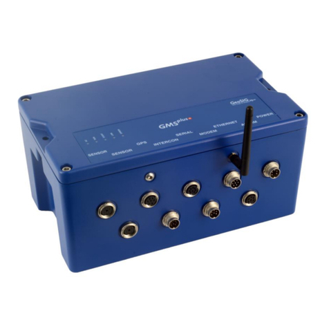
GeoSIG GMS plus Owner's manual

GeoSIG
GeoSIG GMS plus User manual

GeoSIG
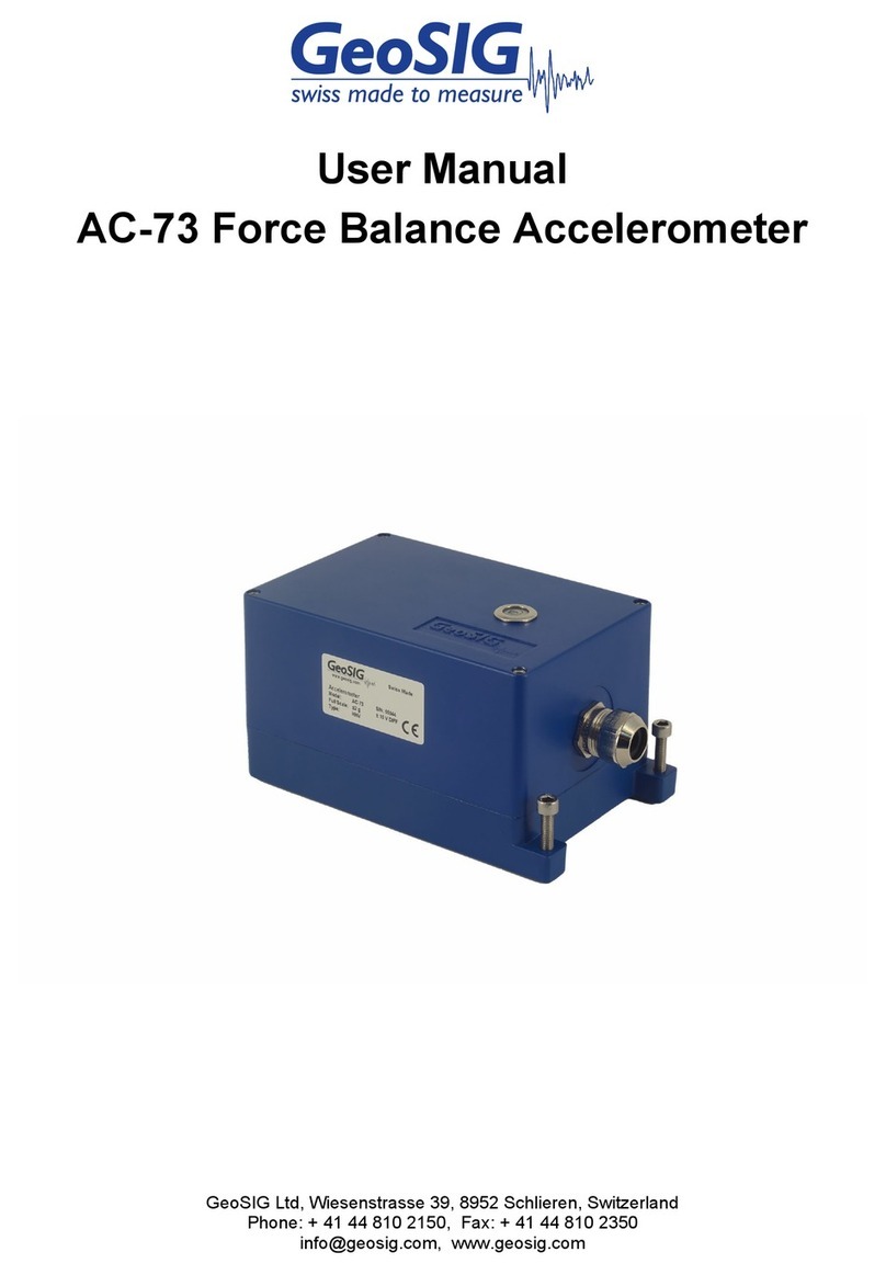
GeoSIG AC-73 User manual

GeoSIG
GeoSIG AC-23 User manual

GeoSIG
GeoSIG AC-73-DH Installation and operating instructions

GeoSIG
GeoSIG GMS-GPS User manual

GeoSIG
GeoSIG GMS plus Installation guide

GeoSIG
GeoSIG GMS-scai Installation guide

GeoSIG
GeoSIG GSR Series Owner's manual