The IPG5000 needs to be powered by external 230 V / 50 Hz or optional 115 V / 60
Hz. If voltage drops below 210 V the system is not operating. Output energy of the
IPG5000 is 1000 J @ 5000 V.
Impulses can be released in single or continuous mode either by using the remote
control unit RCU or by using the controls at the IPG5000 control panel. The HV-output
has no direct contact to the generator housing, i.e. the terminals +HV and -HV are
connected to housing and ground via two resistors of 15 Meach.
To prevent electromagnetic interference the generator should be operated in a
certain distance to the seismograph. Avoid crossing cables.
Attention:
The impulse generator must be protected from any wetness, e.g. rain and dust!
Before switching “ON”the ground terminal of generator must be connected to
ground using the grounding hook via the yellow-green cable. If the ground is
very dry add water to the grounding hook to enable a good soil contact.
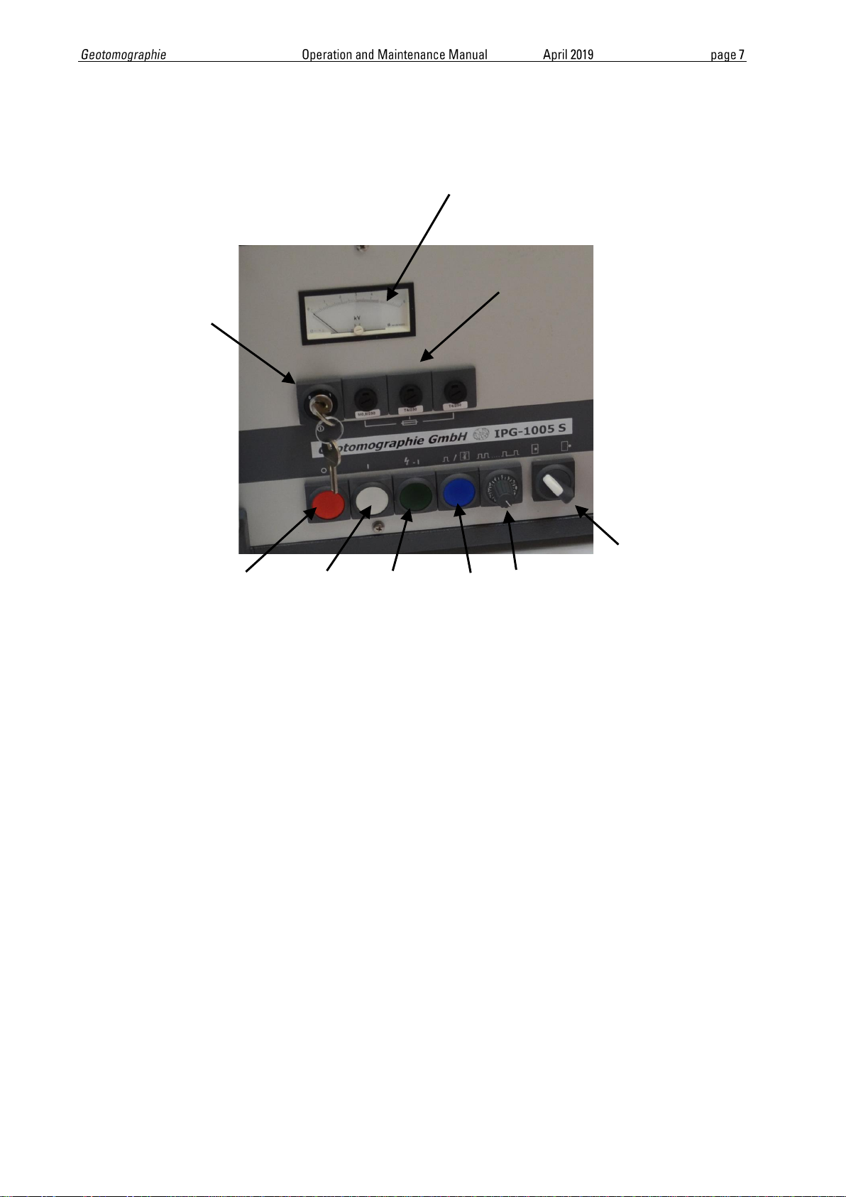
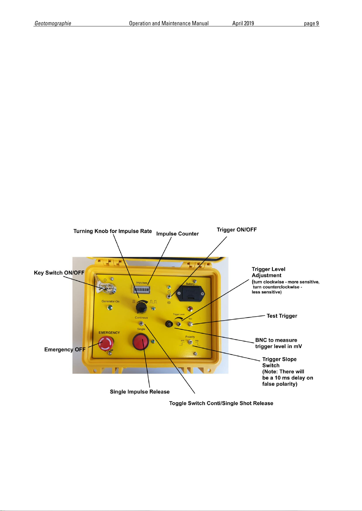
1.1 Connections at IPG5000 and set-up
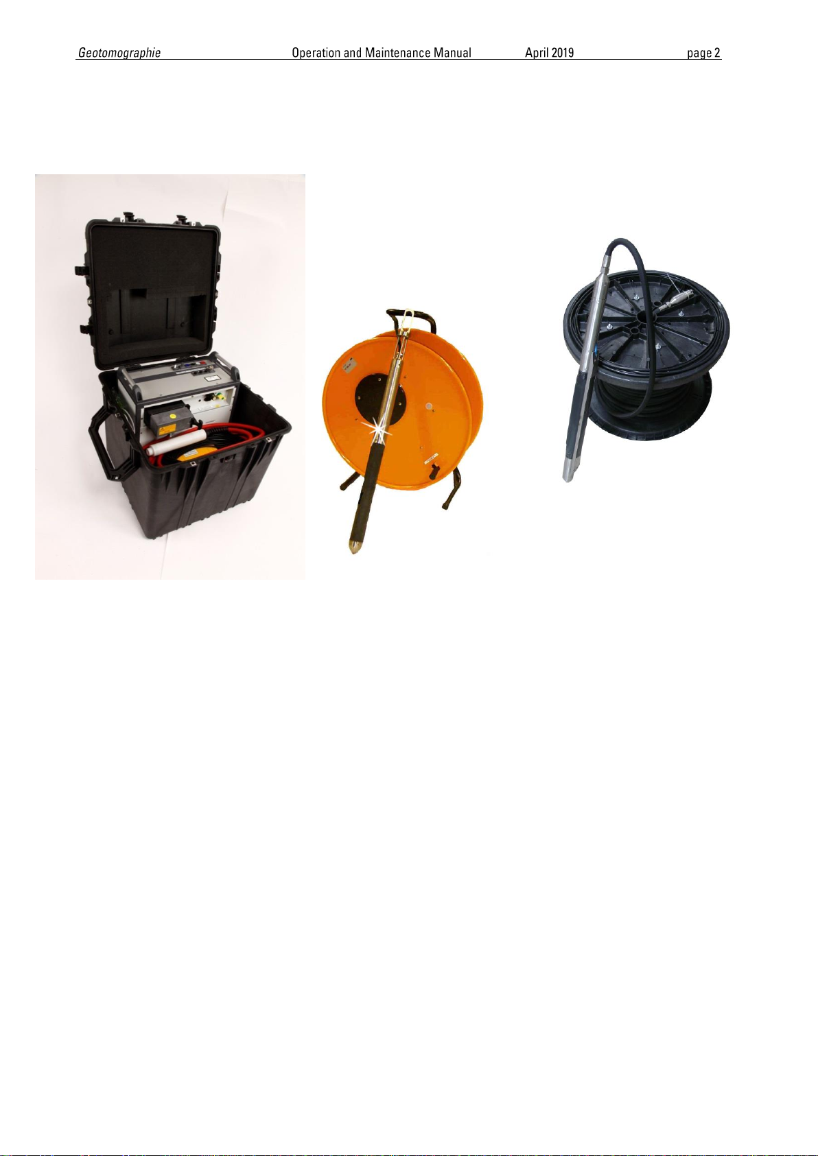
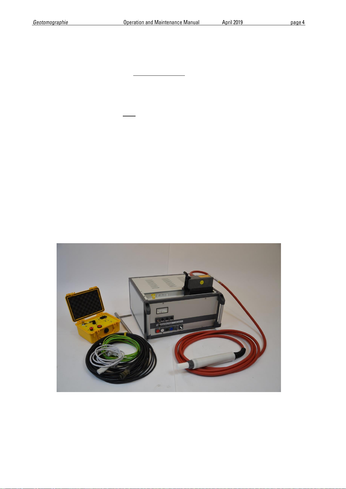
Following accessories for operation of the impulse generator are delivered:
1. Grounding hook with cable (colour yellow/green)
2. Power supply cable (grey) with connector (type suitable to national standards)
3. Remote control unit with cable (black)
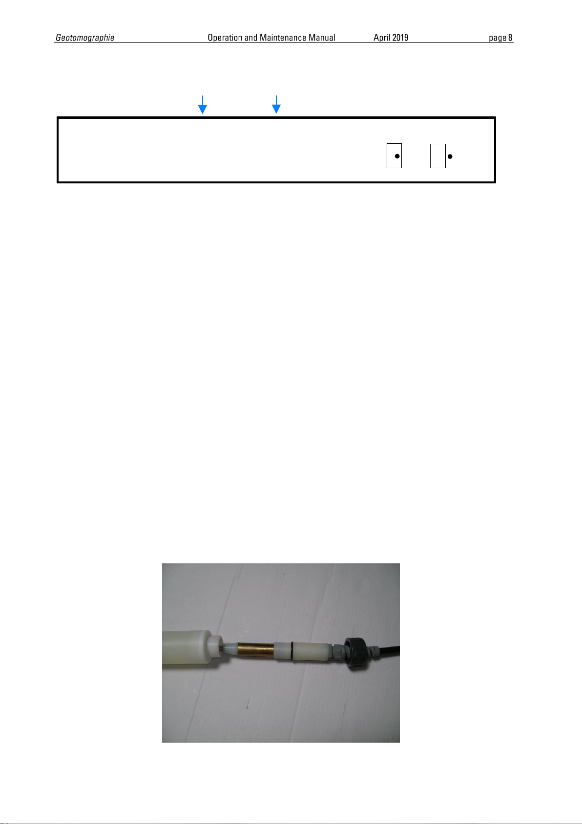
4. High-voltage surface cable (big red cable) for connection between impulse
generator and borehole cable having a length of approx. 6 m equipped with a
coaxial quick connector (sleeve part) for connection to surface connector of the
borehole coaxial cable.
Please follow the instruction below to connect cables to IPG5000.
Connect the cables to the IPG5000 is in same order (from 1 to 4).
Do not connect power cable to external power supply. This shall be done at last
after setting up all other connections.
Disconnect the cables from the IPG5000 is in same order (from 4 to 1) but
switch off unit first and disconnect VAC.
NEVER disconnect while under operation or while the unit is charged.
Next, the borehole probe SBS42 or BIS-SH can be connected to the IPG5000 through
the big red HV cable (see chapter 5.3/5.4).