Operation and Maintenance Manual May 2023
page 3
Geotomographie GmbH, Am Tonnenberg 18, 56567 Neuwied (Germany)
Tel.: +49 2631 778135 email: info@geotomographie.de
1. Introduction
High-resolution P-wave tomographic investigations between boreholes are routinely applied for the
exploration of development sites considered for larger building projects, e.g. power stations, dams and
high-rise buildings. However, the geotechnical benefits of P-wave tomography are rather limited and
information about S-wave velocity distribution is additionally required to derive geotechnically relevant
parameters, such as dynamic soil parameters. Up to now, only little efforts have been made to develop
equipment enabling the competitive acquisition of S-wave crosshole tomographic data.
The Multistation Borehole Acquisition System (MBAS-D) is designed to efficiently acquire S-waves in
dry and water-filled boreholes at different levels. The system is digital and does not require a
seismograph. Each station is equipped with a 3C sensor array and is pneumatically coupled to the
borehole wall by two pressure cylinders.
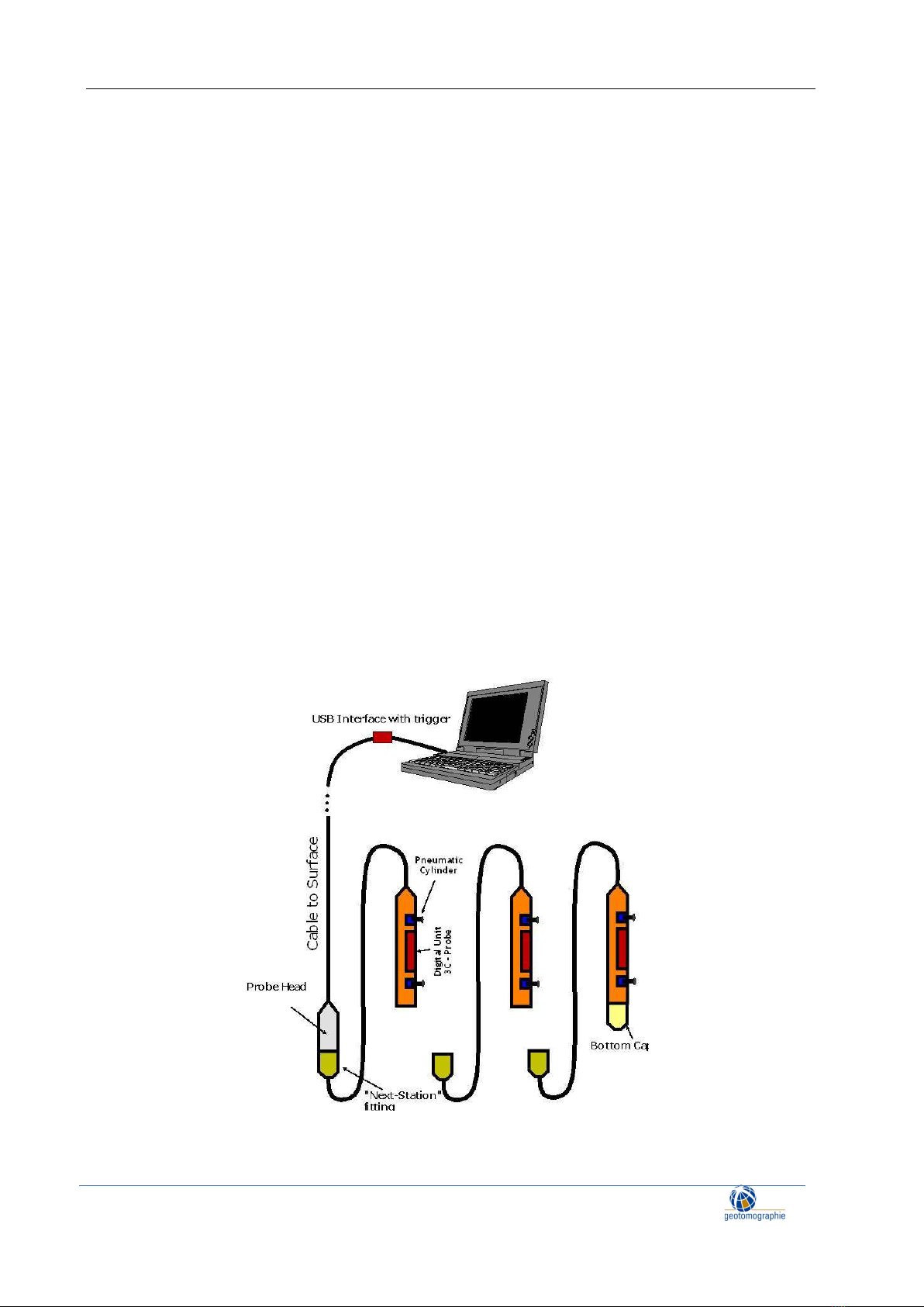
2. General set-up of the MBAS-D
The Digital Multistation Borehole Acquisition System (MBAS-D) is a digital three-component geophone
string which does not require a separate seismograph. Up to ten individual stations with a tri-axial sensor
array can be connected. The stations are aligned to ensure that all horizontal sensors are oriented in same
direction meaning that all X and Y components are aligned. To orientate the MBAS to an optimum
recording position, a rotating string hose is used. The hose is flexible for winding on a drum, but stiff
when trying to rotate it. This makes it easy to turn the MBAS in any direction.
Figure 1: General set-up of the MBAS-D