Geovent GEOFILTER GFO 315 User manual

Version 1.0 31.10.19
INSTRUCTION MANUAL
www.geovent.com
GEOFILTER
GFO 315

2

3
Table of Contents:
1.0 General safety precautions………………………. 2
1.1 Danger……………………………………………… 2
1.2 Field of application………………………………… 2
1.3 Technical data……………………………………... 2
1.4 Construction…………………………………………3
2.0 Installation. . ………………………………….. . . . .3
2.2 Test Run - adjusting . . . . . . . . . . . . . . . . . . . . . . 3
3.0 User instruction………………….. . . . . . . . . . . . . .4
4.0 Maintenance… . . . . . . . . . . . . . . . . . . . . . .. . . . . 4
4.1.2. Replacing filter cartridges…. . . . . . . . . . . . . . . 4
4.2 Trouble shooting . . . . . . . . . . . . . . . . . . . . . . . . . 6
5.0 Liability . . . . . . . . . . . . . . . . . . . . . . . . . . . . . . . . . 6
6.0 Declaration of conformity . . . . . . . . . . . . . . . . . . . 8
1.0 General safety precautions
Remember always to read the manual. General
maintenance and replacement of filter media demands
careful reading of section 4.
Do not dismantle the factory-mounted parts, because
the commissioning of the media.
1.1 Danger
It is extremely dangerous to dismantle original parts of
GFO 315 filter while it is in use.
Before installation or service of GFO 315 filter, make
surePower is disconnected.
1.2 Field of application
GFO 315 used for filtering of oil-saturated air from indu-
strial processes.
The filter cannot be used in areas classified as ATEX
zones, for example for aluminum, flour and wood dust
and other media associated with danger of explosion.
GFO 315 comes with filter cartridge of 100% polyester.
Install the filter indoors, to prevent condensation pro-
blems.
1.3 Technical data
Table of dimensions
EntleerungsHAHN
150
400
Airflow [m³/h]
Pressure drop [Pa]
800 1200
300
450
600
750
900
1050
1200
1350
1500
1650
GFO filter
200 600 1000 1400 1600 1800 2000 2200
Lower curve = clean filter
Upper curve = dirty filter

4
1.4 Construction
A qualified person should only do the following installa-
tion.
2.0 Installation
GFO 315 filter should be installed indoors, for example
technical room with good ventilation for safe operation.
FILTER IS NOT SUITABLE FOR OUTDOOR LOCATI-
ON.
Consider the optimum installation area before installa-
tion. Is placement of the filter inside possible? Is there
space enough installation and service of GFO 315 filter?
Is there optimal connectivity for piping?
Make sure that there is sufficient ground clearance, so
you can disconnect GFO filter lid when replacing the fil-
ter cartridge. At the bottom of GFO filter there must be
room for the filter to drain the oil from the mounted tank
drain tap.
It must be ensured, that the pipe from the drain tap forms
a water trap, so that air or oil is not sucked back into the
filter.
Procedure:
1. GFO 315 filter is inserted in the vertical duct
system or console (See picture p.5)
2. The GFO 315 to be connected circular spiral
ventilation duct (SPIRO) on both clean and dirty side.
(The lower pipe connection is always dirty side).
Remember to seal the connection with joint compound
and/or tape!
3. To ensure the free blending, should the return be
two meters the roof ridge to the atmosphere with a
return rate of at least 8 m/s.
It is advisable to check if the ventilation system supplies
the airflow, as the system is sized to. Measure the airflow
and adjust using adjustment damper. In case of overca-
pacity the power consumption (amps) may exceed the
motor of the fan capacity. If so, the motor will burn off.
See the manual for the fans.
2.2 Test Run - adjusting
When the filter has been mounted and properly installed,
ready to use, there will be no interaction between user
and filter. Of course, the user must be aware of is the
correct flow in the system. In these cases, see section
3.0 Anvendelse - Brugerinstruktion
Once the filter is mountet and installed, ready to use,
there will be no user-filter interaction. Of course, the user
must be aware of the correct suction in the exhaust sy-
stem. In these cases see pkt. 4.0 Maintenance.
Filterpatroner
The filter media must drip off 8 hours a day.
4.0 Maintenance
A qualified technician should inspect the entire exhaust
ventilation system - at least once a year.
Periodic maintenance:
• Check pressure drop across filter and replace
filter cartridges, if this exceeds 1500 Pa.
• Check the filter’s clean side of oil or dust
particles periodically and replace filter cartridges
in the event of leaks.
• Empty the filter reservoir of oil using the drain
tap at the bottom.
Exhaust
Air flow
Drain Tap
Cartridge
Water trap

5
4.1.2. Replacing filter cartridges
After about 4.000-8.000 hours of operation or max. 4
years should the filter media be replaced.
(Depending on the load.)
If you have access to remove, the filter cylinder head is
procedure as following:
1. It is important that the service technician is wearing
the appropriate personal safety precautions. Such as re-
spirators and gloves that comply with Danish Working
Environment Authority rules.
2. Loosen the upper clamp on the filter. Lift the top of to
gain access to the top plate in which the filter cartridge
is mounted.
3. Undo the filter cartridge from the top cover by remo-
ving the four screws as shown in the picture above.
4. Save the top plate - it must be mountet on top of the
new filter cartridge.
5. Pull carefully the contaminated filter in a plastic bag,
which is sealed and disposed of in accordance with the
rules on disposal of oil and chemical waste.

6
6. The new filter cartridge is carefully placed, (so the me-
dia is not damaged) then mount the top plate and secure
it with the four screws
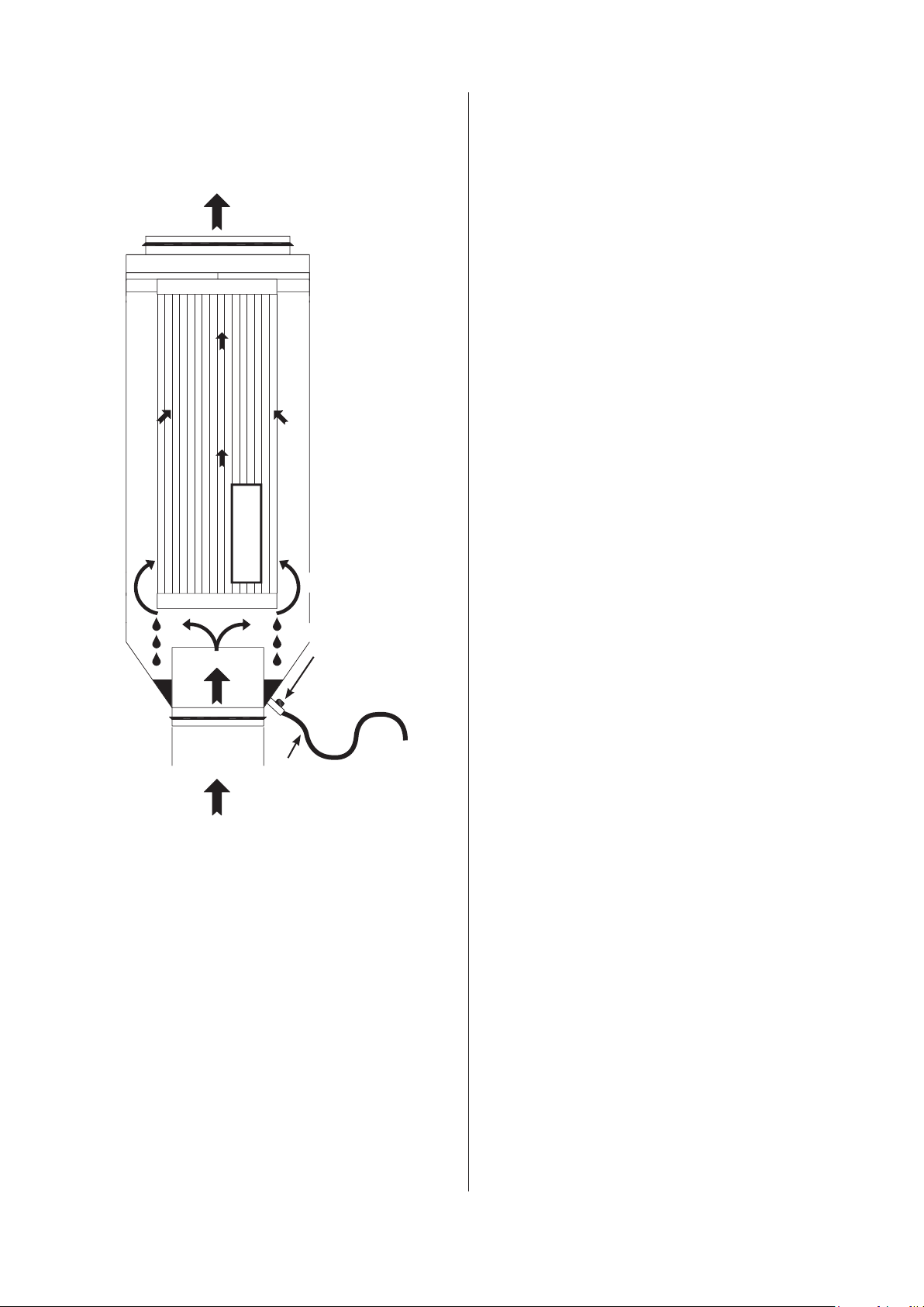
NB:
Remember to mount the filter cartridge with the opening
facing upwards.
7. The lid is gently moved into place and secured with
the previously removed bolts. Slide the lid down slightly
to make sure it is properly positioned.
8. Put the top plate with the filter cartridge back into the
cabinet. Put the top on the filter and tighten the clamp to
assemble the top and the middle piece.
9. Carefully remove the contaminated filter media and
place it in a large garbage bag for proper disposal accor-
ding to local regulations.
Put the top plate with the filter cartridge back onto the
cabinet. Put the top on the filter and tighten the clamp to
assemble the top and the middle piece.
If you cannot remove the filter cylinder head, the proce-
dure is as following:
1. Loosen both clamps on the filter as indicated in the
picture below.
2. Remove the middle piece and replace the filter.
NB:
Remember to mount the filter cartridge with the
opening facing upwards.
4.2 Trouble shooting
Problem: The filter does not absorb, as it
should.
Potential solution: Check if the filter cartridge is cor-
rectly oriented. Filter cartridge ope-
ning should be facing up.
Problem: There is not enough airflow.
Potential solution: Check if replacement of the filter
cartridge is due as mentioned in
paragraph 4.1.2.
Replace the filter cartridge, if that is
the case.
Problem: Noise from the filter.
Potential solution:
Check if the filter cartridge is pro-
perly secured to the top plate.
Secure the filter cartridge.
Problem: Oil in the filter reservoir does not
run out.
Potential solution:
Check if grinding dust or metal
shavings Blocks the drain tap.
Clean, if this is the case.
5.0 Liability
Warranty:
Geovent A/S grants a warranty for products, which are
defective, when it can be proved that the defects are due
to poor manufacture or materials on the part of Geovent.
The warranty comprises remedial action (repair or ex-
change) until one year after the date of shipment.
No claims can be made against Geovent A/S in relation
to loss of earnings or consequential loss because of de-
fects on products from Geovent.
Wear parts as fan wheels and hoses are not included in
the warranty.
User liability:
In order for Geovent to grant the declared warranty, the
user/fitter must follow this Instruction Manual in all re-
spects.
Under no circumstances may the products be changed
in any way without prior, written consent from Geovent
A/S.
Moreover, we refer to the current terms of sale and deli-
very at www.geovent.com.

7
6.0 Declaration of conformity0 EF-o
HOVEDGADEN 86 • DK-8831 LØGSTRUP
hereby declares that:
The product: GeoFilter GFO 315
has been manufactured in compliance with the
following directives and standars:
European Parliament and Council Directive 2006/42/
EC of 17 May 2006 on machinery, and amendments to
Directive 95/16/EC.
EN ISO 14121-1:2007 Risk assessment – part 1
EN ISO 12100-1:2005 Basic concepts and general
principles for design.
EN ISO 12100-1:2009 construction and design
Part 1: Basic terminology and
methodology
EN ISO 12100-2:2005 Basic concepts and general
principles for design.
EN ISO 12100-2:2009 Construction and design
Part 2: Technical principles
Authorized to collect the technical file:
Ole Madsen
Date: 31.10.2019
Position: Managing director
Name: Thomas Molsen
Signature :
Table of contents
Other Geovent Water Filtration System manuals
Popular Water Filtration System manuals by other brands

Honeywell
Honeywell miniplus FK06 Installation instruction

US Water Systems
US Water Systems 385-GWU-1000 owner's guide

Everpure
Everpure Insurice Twin-i20002 Specification sheet

Premier
Premier WP-5 Nstallation, operation and maintenance manual

Hi-Line
Hi-Line ConSEP100 Instruction and maintenance manual

Millipore
Millipore Milli-Q Integral 3 user manual