manuals.online logo
Brands
  1. Home
  2. •
  3. Brands
  4. •
  5. Geovent
  6. •
  7. Water Filtration System
  8. •
  9. Geovent W 3 User manual

Geovent W 3 User manual

W3
dust pre separator
Version 1.0 01.03.16
INSTRUCTION MANUAL
www.geovent.com.pl
2
Contents
1. Function .................................2
2. Description of elements .....................2
3. Installation ...............................2
3.1 Exchange of the clamping bracket .............2
3.2 Use of the plug-on-rubber....................2
3.3 Installation of the bafe plate
and the dust collecting tray...................3
3.4 Resetting of the pressure switch
for the lter control .........................3
4. Maintenace...............................3
BA_Staubvorabscheidung filtoo_150105_GB.doc 2 15.04.2014
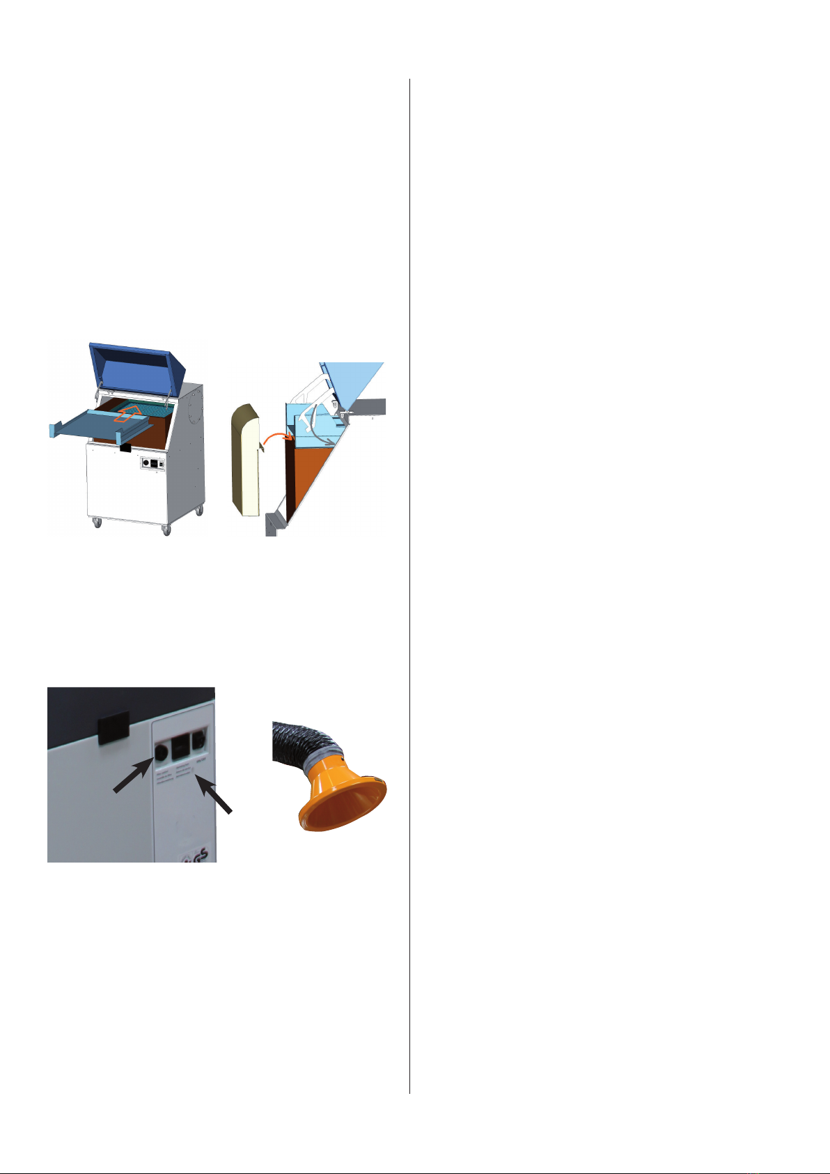
1 Functioning
The spark protection for the unit filtoo can be retrofitted optionally and consists of two components, the
baffle and the collecting tray.
The polluted air is sucked in via extraction elements (e.g. extraction arm) and gets inside the filter unit
via the air intake. There the air hits the baffle plate and is led along the baffle plate towards the collect-
ing tray. At the collecting tray the air deflects by 180°. Thus the air gets into the particle filter. Induced by
the deflection the bigger particles, as for exemple extinct spark particles, fall into the collecing tray and
stay there.
2 Description of elements
Baffle plate
Dust collecting tray
Maintenance door (open)
Clamping bracket
Particle filter
Filter unit filtoo
1. Function
The spark protection for the unit W3 can be retrotted
optionally and consists of two components, the bafe
and the collecting tray
The polluted air is sucked in via extraction elements
(e.g. extraction arm) and gets inside the lter unit via
the air intake. There the air hits the bafe plate and is
led along the bafe plate towards the collecting tray.
At the collecting tray the air deects by 180o. Thus the
air gets into the particle lter. Induced by the deection
the bigger particles, as for exemple extinct spark par-
ticles, fall into the collecting tray and stay there.
2. Description of elements
3. Installation
3.1 Exchange of the clamping bracket
The previous clamping bracket is exchanged with the
two new supplied clamping brackets. The shape of
the previously used clamping bracket determines the
choice of the type to be installed.
When screwing the clamping bracket, the screw must
be tightened; but only to the point where the clamping
bracket is still movable. For this purpose it might be
necessary to exchange the screws against the ones
supplied alternatively.
BA_Staubvorabscheidung filtoo_150105_GB.doc 3 15.04.2014
3 Installation
3.1 Exchange of the clamping bracket
The previous clamping bracket is exchanged against two new supplied clamping brackets. The shape of
the previously used clamping bracket determines the choice of the type to be installed.
When screwing the clamping bracket, the screw must be tightened; but only to the point where the
clamping bracket is still movable. For this purpose it might be necessary to exchange the screws
against the ones supplied alternatively.
Shape of the clamping bracket of the filtoo’s till June 2012 Shape of the clamping brackets of the filtoo’s since July 2012
3.2 Use of the plug-on-rubber
The supplied plug-on-rubber is only used with filtoo’s which have been manufactured since end of 2013
(see information on the type plate).
The plug-on-rubber supports the airflow along the baffle plate. Mount the plug-on-rubber at the inside of
the braces (see arrows). At the position where braces cross the plug-on-rubber has to be gashed.
The plug-on-rubber has no sealing function, but reduces the gap between baffle plate and the braces.
Shape of the clamping bracket
of the W3 till june 2012
Shape of the clamping bracket
of the W3 till since July 2012
3.2 Use of the plug-on-rubber
The supplied plug-on-rubber is only used with W3
which have been manufactured since end of 2013
(see information on the type plate).
The plug-on-rubber supports the airow along the
bafe plate. Mount the plug-on-rubber at the inside of
the braces (see arrows). At the position where braces
cross the plug-on-rubber has to be gashed. The plug-
on-rubber has no sealing function, but reduces the gap
between bafe plate and the braces.
W3
3
3.3 Installation of the bafeplate and
the dust collecting tray
The bafe plate is inserted into the lter unit in the
shown mounting direction (illustration on the left).
The bafe plate lies on top of the particle lter and is
pushed till it is adjacent to the back of the housing.
The dust collecting tray is installed in front of the bafe
plate (illustration on the right). The bracket of the dust
collecting tray must be hung in the front frame of the
particle lter.
Finally the maintenance door is to be closed. The clam-
ping brackets on the bafe plate must thereby move
inside the housing.
BA_Staubvorabscheidung filtoo_150105_GB.doc 4 15.04.2014
3.3 Installation of the baffle plate and the dust collecting tray
The baffle plate is inserted into the filter unit in the shown mounting direction (illustration on the left).
The baffle plate lies on top of the particle filter and is pushed till it is adjacent to the back of the housing.
The dust collecting tray is installed in front of the baffle plate (illustration on the right). The bracket of the
dust collecting tray must be hung in the front frame of the particle filter.
Finally the maintenance door is to be closed. The clamping brackets on the baffle plate must thereby
move inside the housing.
3.4 Resetting of the pressure switch
for the lter control
The W3 is equipped with a lter control as a standard
feature which monitors the degree of saturation of the
lter element. Details on this can be found in the sepa-
rate operating manual of the W3. The hooter (A) begins
to sound when the lter control is triggered.
4 Maintenance
The dust collecting tray must be cleaned at regular in-
tervals. The intervals depend on the produced quantity
of dust and thus cannot be predetermined.
The negative pressure in the device changes when the
dust pre-separator is used and the lter control would
then indicate a lter alarm at an early stage. Therefore,
it is necessary to reset the pressure switch accordingly.
Proceed as follows:
. The bafe plate and the collecting tray must be
installed and the maintenance door must be closed
as specied in chapter 3.3
.Place a piece of cardbord in front og the hood, so if
covers app. 90% of the opening
 (This,incombiationwithnewlterelementsgene-
rates a negative pressure comparable to saturated
lterelementswithanopenhood.)
.Remove the masking cap (B). Here the alignment
of the pressure switch is located.
.Now turn on the W3. Adjust the alarm value of the
pressure switch while the W3 is on.
Adjust the pressure switch by inserting a torx
screwdriver (T25 -T27) or at-bladed screwdriver
(size 2 - 3.5) into the alignment aperture.
Turn the alignment clockwise till the signal hooter
stops. Now turn counter-clockwise till the signal
hooter restarts to sound. In this position the pres-
sure switch is optimally set.
.Reattach the masking cap.
AB
HOVEDGADEN 86 • DK-8831 LØGSTRUP
www.geovent.com.pl
Dystrybucja w Polsce
tel.+48 799923945
E-mail:[email protected]

Other Geovent Water Filtration System manuals

Geovent GeoFilter GFO-XT Series User manual

Geovent

Geovent GeoFilter GFO-XT Series User manual

Geovent GF 315 User manual

Geovent

Geovent GF 315 User manual

Geovent GEOFILTER GFO 315 User manual

Geovent

Geovent GEOFILTER GFO 315 User manual

Geovent GEOGO User manual

Geovent

Geovent GEOGO User manual

Geovent GEOFILTER GFB2 W3 User manual

Geovent

Geovent GEOFILTER GFB2 W3 User manual

Geovent Dustbox CFU-1000 User manual

Geovent

Geovent Dustbox CFU-1000 User manual

Popular Water Filtration System manuals by other brands

Growonix EX100 owner's manual

Growonix

Growonix EX100 owner's manual

Aquatec Equipment AquaPRO AP5000UV user manual

Aquatec Equipment

Aquatec Equipment AquaPRO AP5000UV user manual

Ritual Electronics Altar manual

Ritual Electronics

Ritual Electronics Altar manual

Kinetico K5 owner's manual

Kinetico

Kinetico K5 owner's manual

Hydac FAM10 FluidAqua Mobil Operating and maintenance instructions

Hydac

Hydac FAM10 FluidAqua Mobil Operating and maintenance instructions

Kohler K-80021T-KPC40-01R installation guide

Kohler

Kohler K-80021T-KPC40-01R installation guide

PureEffect ULTRA-UC-DISINFECT manual

PureEffect

PureEffect ULTRA-UC-DISINFECT manual

elysator PUROTAP expert Installation and operation maintenance

elysator

elysator PUROTAP expert Installation and operation maintenance

Excalibur EWR 5100C Installation and user guide

Excalibur

Excalibur EWR 5100C Installation and user guide

JRC NSVS779 manual

JRC

JRC NSVS779 manual

Esta SRF K-10 operating instructions

Esta

Esta SRF K-10 operating instructions

Sanborn Freddy TOS user manual

Sanborn

Sanborn Freddy TOS user manual

Sub-Zero ELECTRI-COOL II Operation manual

Sub-Zero

Sub-Zero ELECTRI-COOL II Operation manual

TotalPond 52301 instruction manual

TotalPond

TotalPond 52301 instruction manual

Philips Saeco AquaClean CA6903 quick start guide

Philips

Philips Saeco AquaClean CA6903 quick start guide

Intex 26669EG owner's manual

Intex

Intex 26669EG owner's manual

LiquaGen 6 stage installation manual

LiquaGen

LiquaGen 6 stage installation manual

Netafim 25AP46 Series Installation, operation & maintenance instructions

Netafim

Netafim 25AP46 Series Installation, operation & maintenance instructions

manuals.online logo
manuals.online logoBrands
  • About & Mission
  • Contact us
  • Privacy Policy
  • Terms and Conditions

Copyright 2025 Manuals.Online. All Rights Reserved.